1
dc1160f
DEMO MANUAL DC1160
DESCRIPTION
LT3518: Full-Featured
LED Driver with 2.3A
Switch Current
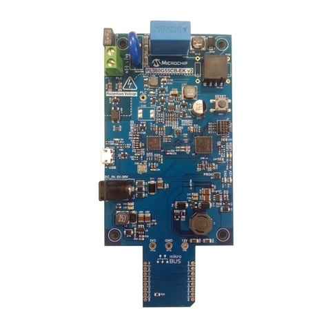
Demonstration circuit 1160 is a full-featured LED driver
with 2.3A switch current featuring the LT
®
3518. The board
is optimized to drive a 330mA LED string with a total LED
voltage between the input voltage and 40V in a boost to-
pology. The high input voltage range, high efficiency low
side internal 2.3A NPN power switch, low voltage floating
current sense amplifier, soft-start, high side PMOS PWM
gate driver, high PWM dimming ratio, overvoltage protec-
tion, shutdown control pin, analog LED current dimming
control,andexternallyprogrammableswitchingfrequency
(with sync) make the LT3518 an extremely versatile and
powerful LED driving IC.
The LT3518 has a 45V switch with 2.3A peak switch cur-
rent limit rating. DC1160 has overvoltage protection at
40V if the LEDs are open or not properly attached to the
terminals on the PCB. The shutdown function is activated
by pulling the shutdown terminal to ground. In shutdown
the boost configuration allows the input voltage to be seen
on the output and if the attached LED array leaks current
at the input voltage, the LEDs may not completely turn off.
If the top gate is installed, it will provide shutdown output
disconnect and the LEDs will turn off during shutdown.
The CTRL terminal can be used to analog dim the LED
current. In order to use the CTRL terminal, R6 (0Ω) pull-
up short resistor must be removed and replaced with a
resistor divider from VREF to GND or an external voltage
on the CTRL terminal.
L, LT, LTC, LTM, Linear Technology and the Linear logo are registered trademarks of Linear
Technology Corporation. All other trademarks are the property of their respective owners.
The high side PMOS PWM dimming MOSFET can be
used to achieve 3000:1 PWM dimming ratio. The board
is programmed for 1MHz oscillator frequency, but can
be adjusted by changing R14. Higher frequency results
in higher PWM dimming ratio.
The VIN pin can be tied directly to PVIN for simplicity or
powered from an additional low voltage input such as
3.3V for higher efficiency operation and lower on-chip
power dissipation.
A few simple modifications can be made to DC1160 in
order to convert the board from a boost LED driver to a
buck mode or buck-boost mode LED driver. Please consult
the data sheet for schematic details and the factory for
customization details.
The LT3518 data sheet gives a complete description of the
part, operation andapplicationsinformation. The datasheet
must be read in conjunction with this Quick Start Guide for
demonstration circuit 1160. The LT3518 is assembled in a
small 16-lead plastic (4mm ×4mm) QFN UF package with
a thermally enhanced ground pad. Proper board layout is
essential for maximum thermal performance. See the data
sheet section Layout Considerations.
Design files for this circuit board are available at
http://www.linear.com/demo
Downloaded from Elcodis.com electronic components distributor
