Linear LTC4002-4.2 User manual

QUICK START GUIDE FOR DEMONSTRATION CIRCUIT 551
LITHIUM-ION BATTERY CHARGER WITH CHARGE TERMINATION
1
LTC4002-4.2
DESCRIPTION
Demonstration circuit 551 is a complete constant-
current/constant- voltage battery charger designed
to charge one Lithium-Ion cell. Programmed for 3A
charge current, this board features a 500kHz step
down switching regulator controller driving a P-
channel MOSFET. A fixed 3 hour timer is included
for charge termination in addition to a charge status
LED to indicate a near-full-charge condition and a
thermistor connection for battery temperature
charge qualification. Because of the heat generated
by the circuit, the thermistor must not be mounted
on this board. A 10k resistor (R3) is used instead of
a thermistor on this board.
The LTC
®
4002 on this board is in a tiny 3 X 3 mm
10 pin DFN package. All surface mount components
are used to minimize board space and height with
the circuitry occupying approximately 0.5 square
inches of board space although additional pc-board
copper is needed for heat dissipation.
Design files for this circuit board are available.
Call the LTC factory.
LTC is a registered trademark of Linear Technology Corporation
Other Features include:
•Preset float voltages of 4.2V ±1%
•3A Constant Current (can be programmed for other charge currents)
•3 Hour charge termination timer
•NTC Thermistor input for sensing battery temperature
•Undervoltage Lockout
•Manual Shutdown
•Low battery drain current when input supply is removed
•C/10 Trickle charge for deeply discharged batteries
•Auto recharge when battery voltage drops below preset threshold
•C/5 Charge LED indicator (CHRG)

QUICK START GUIDE FOR DEMONSTRATION CIRCUIT 551
LITHIUM-ION BATTERY CHARGER WITH CHARGE TERMINATION
2
Typical Demo Board Specifications
* Main cause of drain current is due to Schottky diode leakage current.
Figure 1. Test Setup
Test Equipment Required for Demo Board Evaluation
Input Voltage Range (V
IN
) 5.2V to 24V
Charge Voltage (V
BAT
) (constant voltage mode) 4.2V ±1%
Charge Current I
BAT
(constant current mode) 3A ±8%
Charge Current IBAT (trickle current mode) 350mA ± 20%
C/5 CHRG LED Threshold Level 750mA ± 25%
Trickle Charge Threshold Voltage 2.9V
Battery Drain Current with VIN Removed <20µA *
Lab power supply for input power 0 to 25V @ 3A
Digital multimeter for measuring input voltage (V
IN
) 3-1/2 digits
Digital multimeter for measuring battery voltage(V
BAT
) 4-1/2 digits
Digital multimeter for measuring charge current 3-1/2 digits
Li-Ion cell or
*Battery Simulator
4.2V Rechargeable Li-Ion Cell
Input
Power
Supply
0 to 25V
@3A
+
-
Battery
Simulator
Bench Power
Supply
0V to 5V
@6A
+
-
Course Fine
Voltage Adjust
Volt
Meter
Measure Charge Current
3 ea.
2 Ohm
10W
L
i
-
I
o
n
B
a
t
t
e
r
y
S
i
m
u
l
a
t
o
r
Measure Charger
Output Voltage (V
BAT
)
Volt
Meter
Measure Input Voltage
+V
IN
GND
BAT
GND
LTC4002EDD
Demo DC551A
(408)432-1900
TECHNOLOGY
EXT
NTC
Preload
Resistors
Volt
Meter
0.1 Ohm
1%
100mV/Amp
SHDN/RUN Jumper
CHARGE LED
NTC Thermister (10k Resistor)
(I
BAT
)
Current
Sense
Resistor

QUICK START GUIDE FOR DEMONSTRATION CIRCUIT 551
LITHIUM-ION BATTERY CHARGER WITH CHARGE TERMINATION
3
*Battery Simulator consists of;
Battery Simulator
A battery simulator can be very useful for
evaluating a battery charger. A simple battery
simulator consists of a lab power supply with
coarse and fine (or a multi-turn) voltage adjust
controls and a power resistor connected to the
power supply output terminals. With the resistor
load connected, the power supply can source and
sink current, similar to an actual battery. Any level
of charge from a fully discharged to fully charged
battery can be quickly simulated by simply
changing the battery simulator power supply
voltage. A fully discharged Li-Ion cell will be
approx. 2.6V to 3V and a fully charged cell will be
either 4.1V or 4.2V depending on the battery
chemistry. When the cell is nearly fully charged,
small changes in battery voltage will result in large
changes in charge current.
Of course, there are times when an actual battery is
needed, for example when plotting a complete
charge cycle from start to finish.
QUICK START PROCEDURE
With both power supplies set to 0V, connect the
demo board to power supplies and meters as
shown in Figure 1. The electrical connections
between the charger output and the battery
simulator must be high quality and a 0.1
Ω
sense
resistor is recommended for the charge current
measurement. The dc resistance in the charge
current path should be kept to a minimum.
Undervoltage Lockout and Trickle Charge - After
placing jumper (JP1) in the “RUN” position, begin
increasing the input power supply voltage. At
approximately 4.3V, the LTC4002 undervoltage
lockout will allow the charger to start and the
charge current will abruptly rise to approximately
300mA (30mV on the meter). This is the trickle
charge current for a deeply discharged battery (V
BAT
< 2.9V). Adjust the input supply to approximately
6V.
Trickle Charge Threshold and Constant Current
Charge - Begin increasing the battery simulator
power supply (V
BAT
), observing the charger output
voltage on the DVM. When the voltage exceeds
approximately 2.9V, the charger will suddenly enter
the Constant Current portion of the charge cycle
resulting in an abrupt increase in charge current to
the programmed value of approximately 3A (300mV
on the charge current DVM). This is the constant
current mode. The CHRG LED will also turn on.
Constant Voltage Charge and CHRG LED Indicator -
Continue slowly increasing the battery simulator
power supply, thus simulating a battery accepting
charge. The charge current should remain at the
programmed value of 3A until the charger output
voltage is within approximately 10mV of the preset
charge voltage (4.2V ±1%), at which time the charge
current will begin to decrease. This is the beginning
of the Constant Voltage portion of the charge cycle.
Continue very slowly increasing the battery
simulator power supply until the CHRG LED turns
off, and note the charge current level when it went
off. The current level should be approximately
750mA ±25%. The LED is an indicator that the
battery is approaching full charge. It is not a charge
complete indication. The charge cycle will continue
until the 3 hour timer ends. (Note: when the LED
Power supply with coarse and fine output voltage adjust controls 0 to 5V @ 6A
Power resistors (preload for power supply) 3ea 2
•
10W

QUICK START GUIDE FOR DEMONSTRATION CIRCUIT 551
LITHIUM-ION BATTERY CHARGER WITH CHARGE TERMINATION
4
turns off, it remains off until a new battery is
installed, the input power is cycled, or the charger is
momentarily shut down).
Continue increasing the battery simulator power
supply until the charge current drops to
approximately 300mA (30mV on the charge current
DVM), then read the charger output voltage on the
DVM. This reading is the charger float voltage of
4.200V ± 40mV. Note: small changes in battery
simulator voltage will result in large changes in
charge current. Adjusting the simulator power
supply to 4.2V will drop the charge current to 0mA.
Sleep Mode - To verify battery drain current in the
sleep mode, remove the input supply voltage or shut
the supply off, replace the 0.1
Ω
current sense
resistor with a 1k
Ω
, and set the battery simulator
power supply to approximately 4V. The charge
current DVM will now read battery drain current with
1mV/µA.
Misc - The input voltage can range from 5.2V to 24V
with negligible effect on charge current or charge
voltage specs. When applying input voltage greater
than 20V, a solid tantalum capacitor is
recommended in parallel with the existing ceramic
input bypass capacitor to minimize voltage
transients due to ringing when the input power is hot
switched. Install a 10µF or larger, 35V tantalum
capacitor at location C2 on the demo board.
The charger can be shutdown by moving the jumper
(J1) from the “RUN” position to the “SHDN”
position.
To verify the temperature qualification feature,
remove the 10k resistor R3 and connect a resistor
substitution box to the “EXT NTC” terminals. Refer
to the LTC4002 data sheet for resistor values that
will either allow the charger to provide charge
current or stop charging because of temperature
extremes. If an actual thermistor is used, it must be
mounted near the battery, not on the board.

QUICK START GUIDE FOR DEMONSTRATION CIRCUIT 551
LITHIUM-ION BATTERY CHARGER WITH CHARGE TERMINATION
5
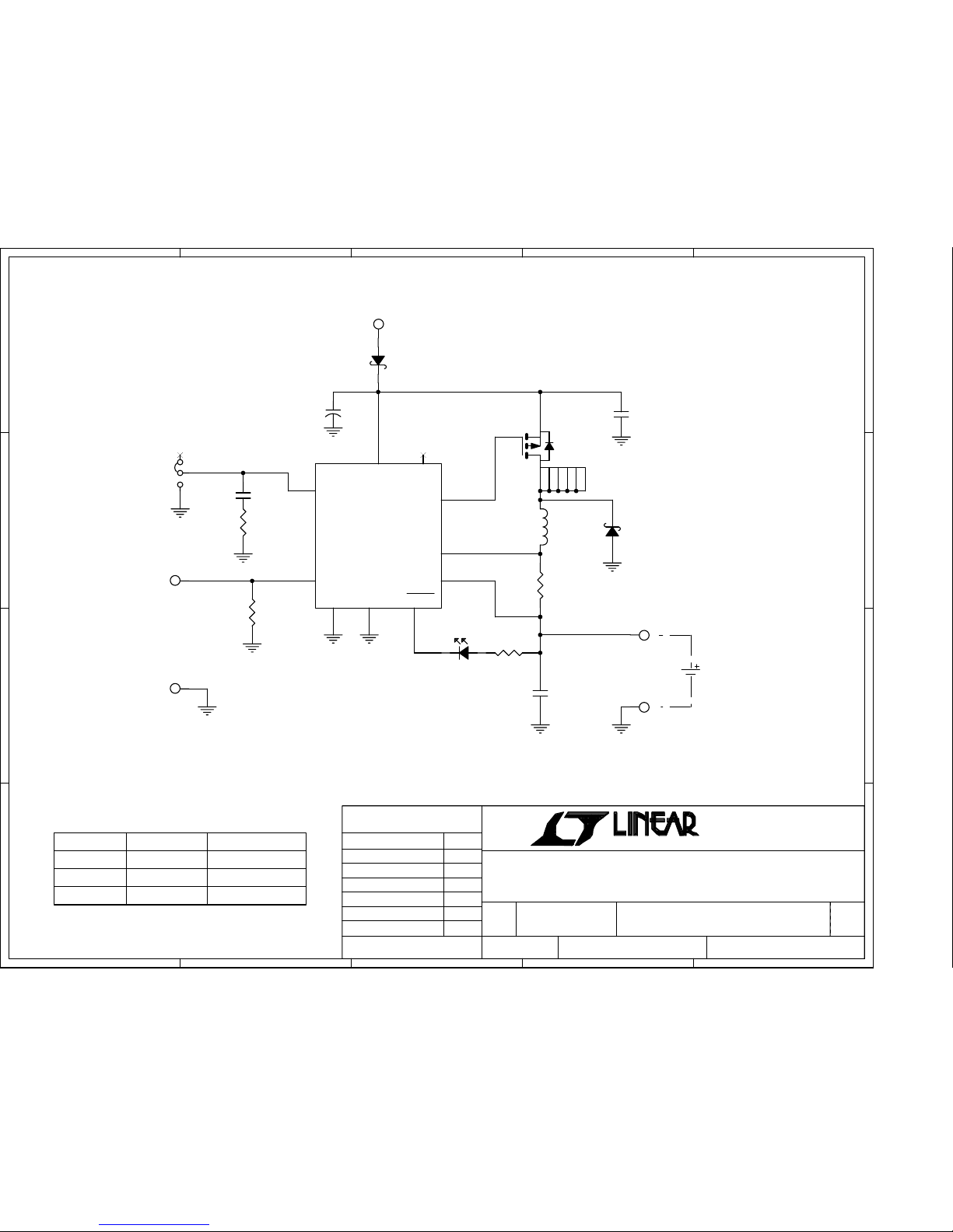
5
5
4
4
3
3
2
2
1
1
D D
C C
B B
A A
Li-lon Battery
5.2V to 24V
+VIN
SHDN
Ext NTC
GND
+BAT
GND
U1VERSION
*
DC551A-A 4.2V
Battery Voltages
VERSION TABLE
LTC4002EDD-4.2
RUN
3A
CHARGE
*
**
13.5V MIN for 12.6V Battery.
*
9.3V MIN for 8.4V Battery.
A
DC551A
Thursday, September 04, 2003
11
June Wu 7/2/02
Fran Hoffart 7/2/02
with Charge Termination
LTC4002EDD, Li-Ion Battery Charger
SIZE
SCALE:
CAGE CODE DWG NO REV
SHEET OF
FILENAME:
TITLE
CONTRACT NO.
APPROVALS DATE
DRAWN
CHECKED
APPROVED
ENGINEER
DESIGNER
TECHNOLOGY
1630 McCarthy Blvd.
Milpitas, CA 95035
Phone: (408)432-1900
Fax: (408)434-0507
R2
0.033
1206
E3
E2
R3
10kNTC
1206
C3
0.47uF
L1
6.4uH
JP1
1
2
3
E4
R4
1k
D3
Green
+
C2
(opt.)
E5
E1
C1
10uF
25V
U1
**
2
13
8
6
9 7
5 4
10
VCC
COMP GATE
SENSE
CHRG
NTC BAT
SGND PGND
NC
C4
22uF
6.3V
Q1
Si5435DC
4
1
2
3
5
6
8
7
D2
B330B
D1
B330B
R1
2.2k

Linear Technology Corporation
LTC4002EDD
Bill Of Material
Demo Bd. #551A-A
6/17/2005
Item Qty Reference Part Description Manufacture / Part #
1 1 C1 CAP., X5R, 10uF, 25V, 20% 1210 Taiyo Yuden, TMK325BJ106MM
2 0 C2 (OPT) CAP., TANT., 7343 OPT.
3 1 C3 CAP., X5R, 0.47uF, 6.3V, 20% 0603 AVX, 06036D474MAT2A
4 1 C4 CAP., X5R, 22uF, 6.3V, 20% 1210 Taiyo Yuden, JMK325BJ226MM
5 2 D1,D2 Schottky Rec., B330B SMB DIODES INC., B330B-13
6 1 D3 LED, Green Panasonic, LN1351C-(TR)
7 5 E1-E5 TESTPOINT, TURRET, .094" MILL-MAX, 2501-2
8 1 JP1 0.079 SINGLE ROW HEADER, 3 PIN COMM CON, 2802S-03-G1
9 1 SHUNT (1-2) SHUNT, COMM CON, CCIJ2MM-138G
10 1 L1 INDUCTOR, 6.4uH, D104C TOKO, 919AS-6R4M
11 1 Q1 P-MOSFET, Si5435DC 1206-8 Vishay Siliconix, Si5435DC-T1
12 1 R1 RES., CHIP, 2.2K, 1/16W, 5% 0603 AAC, CR16-222JM
13 1 R2 RES., CHIP, 0.033, 1/2W, 1% 1206 THIN FILM TECH., RL1632R-R033F
14 1 R3 RES., CHIP, 10k, 1/4W, 5% 1206 AAC, CR18-103JM
15 1 R4 RES., CHIP, 1k, 1/16W, 5% 0603 AAC, CR16-102JM
16 1 U1 I.C., LTC4002EDD DFN10 Linear Tech. LTC4002EDD
17 1 PRINTED CIRCUIT BOARD DEMO CIRCUIT #551A-A
18 1 STENCIL STENCIL #551A-A
Page 1 - of - 1
Table of contents
Other Linear Batteries Charger manuals


