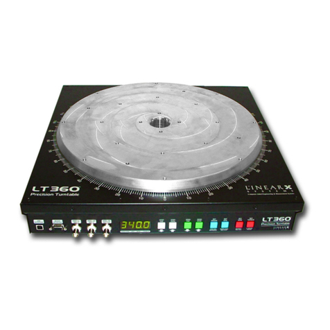
LinearX LT360 User manual

LT360 Precision Turntable
User Manual
LT360 Precision Turntable
User Manual
1
Precision Turntable
User Manual
88
LinearX Systems Inc • 9500 SW Tualatin-Sherwood Rd. • Tualatin, OR 97062-8586 USA
All specifications subject to change without notice.
© 2006 All Rights Reserved.
Printed in the U.S.A.
March-30-2006
Precision Turntable
User Manual
PN: 910-0019
Computer Aided Engineering & Measurement Systems

LT360 Precision Turntable
User Manual
LT360 Precision Turntable
User Manual
2
LT360 Precision Turntable
User Manual
© 2006 LINEARX SYSTEMS INC.
All Rights Reserved.
Tel: (503) 612-9565
Fax: (503) 612-9344
Printed in the United States of America.
March 30, 2006.
This document was produced on a Pentium-4 / 2GHz PC with Win2K using
Adobe PageMaker 7.0, Adobe Illustrator 10.0, Adobe PhotoShop 7.0,
MathType 4.0 for mathematics typography, and SnagIt 5.2 for screen captures.
Final masters were produced using an Xerox Docutech image setter. Help files
were composed and compiled using Windows Help Designer 3.1.
87
9.3 Calibration Certificate (Example)

LT360 Precision Turntable
User Manual
LT360 Precision Turntable
User Manual
3
License Agreement and Limited Warranty
Carefully read all of the following terms and conditions of this agreement before opening and
using the contents of this package. The opening of this package indicates your acceptance of the
terms and conditions of this license agreement. If you are not willing to accept the terms and
conditions of this agreement, then you should return the entire product, with the package seal
unbroken, to the place of purchase for a full refund of the purchase price.
■Copyright Ownership
Both the program and the documentation are protected under applicable copyright laws. LinearX is the holder of this
copyright. Your right to use the program and the documentation are limited to the terms and conditions described herein.
Use of the software unless pursuant to the terms and conditions of this license, or as otherwise authorized by law, is an
infringement of the copyright.
■Limited Non-Exclusive License
You may: (a) use the enclosed program on a single computer, (b) physically transfer the program from one computer to
another provided that the program is used on only one computer at a time, and that you remove any copies of the program
from the computer from which the program is being transferred, (c) make copies of the program solely for backup or archival
purposes. You must reproduce and include the copyright notice and label any backup copy.
You may not: (a) distribute copies of the program or the documentation to others, (b) lease, rent, grant sublicenses, or other
rights to the program, (c) provide use of the program in a computer service business, network, time-sharing multiple CPU or
multiple users arrangement without the prior written consent of LinearX, (d) translate or otherwise alter the program or
related documentation without the prior written consent of LinearX.
■Terms
Your license to use the program and the documentation will automatically terminate if you fail to comply with the terms of this
agreement. Your license terminates in the event that you receive a license for an updated version of the product that
replaces this product. If a license expiration date is printed on your documentation, or provided through other means such
as a time limited electronic or software key, your license expires on the day as shown in the documentation, or on the day that
the electronic or software key expires. If this license is terminated you agree to destroy all copies of the program and
documentation.
86
Power Supply
Power/Type 50W, Universal PFC SMPS
Line Voltage World-Wide 85-265VAC
Line Frequency 50/60Hz
Line Current Sinusoidal, < 10% THD
Switching Freq 150kHz, Spread Spectrum
Standards (TBA, designed to meet)
IEC 60950/61010, UL-1950
CISPR-22, FCC Class-B,
Connector IEC-320 Universal AC Inlet
Acoustic Noise
Broadband 50.4dBspl @ 2M, 1 RPM, ANSI-A Weighted
Spectrum 1/3 Octave density shown below

LT360 Precision Turntable
User Manual
LT360 Precision Turntable
User Manual
4
LinearX Systems Inc., 9500 SW Tualatin-Sherwood Rd.,
Tualatin, OR 97062-8586 USA, TEL:(503) 612-9565 FAX:(503) 612-9344
WEB: www.linearx.com
Copyright 2006, LinearX Systems Inc. All rights reserved. All other Trademarks are the property of
their respective owners.
■Limited Warranty
LinearX warrants to the original licensee that the disk(s) and or electronic key(s) on which the program is recorded will be
free from defects in materials and workmanship under normal use for a period of ninety (90) days from the date of purchase
as evidenced by a copy of your receipt. Hardware products or components have a warranty of 1 year. If failure of the product
components has resulted from accident, abuse, or misapplication of the product, then LinearX or third party licensors shall
have no responsibility to replace the disk(s) or key(s) under this limited warranty.
This limited warranty and right of replacement is in lieu of, and you hereby waive, any and all other warranties, both ex-
pressed and implied, including but not limited to warranties of merchantability and fitness for a particular purpose. The
liability of LinearX or third party licensors pursuant to this limited warranty shall be limited to the replacement of the defective
disk(s) or key(s), and in no event shall LinearX or third party licensors be liable for incidental, indirect, punitive, or conse-
quential damages, including but not limited to loss of use, loss of profits, loss of data or data being rendered inaccurate, or
losses sustained by third parties even if LinearX or third party licensors have been advised of the possibility of such dam-
ages. This warranty gives you specific legal rights which may vary from state to state. Some states do not allow the limitation
or exclusion of liability for consequential damages, so the above limitation may not apply to you.
In addition to the foregoing, you should recognize that all complex software systems and their documentation contain errors
and omissions. LinearX, its distributors, and dealers shall not be responsible under any circumstances for providing informa-
tion on or corrections to errors and omissions discovered at any time in the product, whether or not they are aware of the
errors or omissions. LinearX does not recommend the use of this product in applications in which errors or omissions could
result in loss of life, injury, or other significant loss.
This license agreement shall be governed by the laws of the state of Oregon and shall inure to the benefit of LinearX, its
successors, administrators, heirs and assigns or third party licensors.
■United States Federal Government Restrictions
If this software is acquired by or on behalf of the U.S. Federal government or its agencies, this provision applies. Use,
duplication, or disclosure of this software is subject to restrictions set forth in the appropriate FAR 52.227-19 and DFAR
252.227-7013 documents, as applicable. The software is "commercial computer software" and is licensed only with "Re-
stricted Rights". Other Federal restrictions may also apply.
85
9.2 LT360 Electrical Specifications
Control Panel
Switches (8) Momentary Push Buttons
Display 4 Digit, 7-Segment, 0.56 Inch
Memory Nonvolatile, retention >40 years
LR360 Interface
Connector PS2, MiniDIN-6 Female Jack
USB Interface
Class/Rev Low Speed, 1.5Mbps, USB-1.1
Connector Type-B
RS-232 Interface
Baud Rate 9600 default, 115200 max
Configuration DCE (use straight thru cable)
Connector DB-9 Female
Digital Input
Input Impedance 100k Ω
Pulse Trigger Rising or Falling
Threshold TTL, LVTTL
Hysteresis 0.75V
Pulse Width 10us Min
Connector BNC Jack
Analog Input
Input Impedance 1M Ω
Scale Factor 10mV / Degree
Unipolar Range 0 to +3.600V for 0 to 360°
Bipolar Range -1.800 to +1.800V for -180° to +180°
Driving Source Z 200 ΩMax recommended
Connector BNC Jack
Analog Output
Output Impedance < 1 Ω
Scale Factor 10mV / Degree
Unipolar Range 0 to +3.600V for 0 to 360°
Bipolar Range -1.800 to +1.800V for -180° to +180°
Output Current 5mA Max
Short Duration Unlimited
Connector BNC Jack

LT360 Precision Turntable
User Manual
LT360 Precision Turntable
User Manual
5
Technical Support
LinearX provides detailed printed manuals and on-line help within the program as the primary
source for user information and assistance regarding the use of this product. If these sources
do not contain the answers to your questions, contact LinearX via any of the following meth-
ods:
Internet Forums: www.linearx.com/forums
Internet Web: www.linearx.com
Fax: (503) 612-9344 Tel: (503) 612-9565
Technical support is free and unlimited at this time, however we reserve the right to charge
for this service in the future as conditions, overhead, and support personnel requirements
dictate.
When contacting us regarding a technical support issue, PLEASE follow these steps to aid
us in understanding and solving your problem:
(1) If your question involves specific details or parameters unique to your project and prob-
lem, please include a copy of your design files with the necessary data so that we can
reproduce your problem. This is only possible if you are communicating via an electronic
means such as Email or uploading files directly to our web site.
(2) If the issue regards error messages from the program, please include an exact descrip-
tion of the error message and/or address information that the program reports.
(3) If there are specific steps involved to reproduce the issue, please note these exact steps
required so that we can reproduce the problem.
Note: A free technical support forum is provided on the LinearX web site at
www.linearx.com/
forums
Generally you can find the quickest answers to your questions using this forum which is
available 24 hours a day 365 days a year.
Technical support hours are: Monday-Friday 9:00AM to 5:00PM Pacific Standard Time.
84
Center Through Hole
Diameter 1.5 Inches (38mm)
Platter Dimensions
Height 0.75 Inches (19mm)
Diameter 16.0 Inches (406mm)
Mounting Holes (4) 1/4-20 on 3.0 Inch BCD (76.2mm)
Mounting Holes (8) 1/4-20 on 9.0 Inch BCD (228.6mm)
Mounting Holes (8) 1/4-20 on 15.0 Inch BCD (381.0mm)
Chassis Dimensions
Height 3.3 Inches (84mm)
Width 18.0 Inches (457mm)
Length 18.0 Inches (457mm)
Mounting Holes (8) 1/4-20 on 6.0 Inch BCD (152.4mm)
Mounting Holes (4) 1/4-20 on 12.0 Inch BCD (304.8mm)
Overall Dimensions
Height 4.1 Inches (104mm)
Width 18.0 Inches (457mm)
Length 18.0 Inches (457mm)
Weight 35 lbs (16 kg)

LT360 Precision Turntable
User Manual
LT360 Precision Turntable
User Manual
683
9.1 LT360 Mechanical Specifications
Main System
Operation Mount in any orientation, Ta 0° to 40°C
Platter Cast & Machined Aluminum A356-T6
Base Cast & Machined Aluminum A356-T6
Bearing 5 Inch (125mm) Sealed Ball Bearing ABEC-1
Hub 4 Inch Diameter, 0.8 Inch Wall
Axial Load 1,000 lbs (900 kg) Max, Bidirectional
Radial Load 500 lbs (230 kg) Max
Drive System Irreversible Worm Drive
Scale Accurate Screen Printed 1 Degree
Chassis 16ga Steel
Drive System
Motor NEMA-23 Stepper Motor
Controller Bipolar, Microstepping, Microprocessor
Direction Either Counterclockwise or Clockwise
Shaft 0.375 Inch Dia, Steel 1040
Worm 0.75 Inch SAE 4340 Hardened Steel
Worm Gear 5.75 Inch SAE 65 Phosphor Bronze
Bearing Sealed Ball Bearings ABEC-3
Torque 49 N•M Standard Model, Programmable
Torque 76 N•M HiTorque Model, Programmable
Velocity 0.01 ... 3.0 RPM, Programmable
Acceleration 5 Acceleration Functions
Resolution 0.003125 Degree
Step Size 0.1 Degree Minimum
Backlash ±0.07 Degree Typical
Origin User Resettable

LT360 Precision Turntable
User Manual
LT360 Precision Turntable
User Manual
7
1.1 LT360 Safety ............................................................. 11
1.2 TS360 Safety ............................................................. 12
1.3 LT360 Emergency Stop ............................................. 13
2.1 Rubber Feet ............................................................... 15
2.2 Mounting to the LT360 ............................................... 16
2.3 Mounting to the Platter ............................................. 17
2.4 Mounting to the Base .............................................. 18
3.1 AC Power .................................................................. 21
3.2 Control Methods ........................................................... 22
3.3 Computer Interfaces .................................................... 23
3.4 Pulse Input ................................................................. 24
3.5 Analog Input ............................................................... 25
3.6 Analog Output ............................................................ 26
3.7 LR360 Remote ......................................................... 27
Contents
Chapter 1: Safety First !!! 11
Chapter 2: Mounting 15
Chapter 3: Electrical 21
82

LT360 Precision Turntable
User Manual
LT360 Precision Turntable
User Manual
8
4.1 Mechanical Load Capability ....................................... 29
4.2 Drive System Lubrication ........................................... 30
5.1 Front Panel Functions ........................................ 33
6.1 Acceleration Functions .............................................. 43
6.2 Velocity Profiles ....................................................... 46
6.3 Actual Accel/Velocity Profiles ................................... 47
6.4 Horizontal Torque Capability ....................................... 52
6.5 Vertical Torque Capability .......................................... 54
7.1 Error Messages ........................................................ 57
Contents
Chapter 4: Mechanical 29
Chapter 5: Front Panel 33
Chapter 6: Acceleration 43
Chapter 7: Error Messages 57
81

LT360 Precision Turntable
User Manual
LT360 Precision Turntable
User Manual
9
8.1 LT360 Windows Software ....................................... 65
8.2 Opening an LT360 Link ............................................. 66
8.3 Acceleration Function, Smart Torque ....................... 67
8.4 Motor Home Check .................................................. 68
8.5 Information, Name .................................................. 69
8.6 Step Size, Velocity, Torque ........................................ 70
8.7 Display, Output, Input, Polarity .................................... 71
8.8 Analog Input, Pulse Input, Direction, Trigger ................ 72
8.9 CPU, LDR, USB, Firmware, LT360LIB DLL .................. 73
8.10 Action Buttons ............................................................. 74
8.11 Position Graphic Readouts ....................................... 75
8.12 Calibration Button ........................................................ 76
8.13 Update Button .......................................................... 77
8.14 Test Button .............................................................. 78
Contents
Chapter 8: Application Software 65
80
■Test
Clicking this button will open the Test dialog as shown below.
This dialog provides a means to test the LT360 by rotating the platter for a
period of time, number of cycles, etc. It is mainly used by the factory during
product testing and lubrication.

LT360 Precision Turntable
User Manual
LT360 Precision Turntable
User Manual
10
Chapter 9: Specifications 79
9.1 Mechanical Specifications ........................................ 79
9.2 Electrical Specifications .............................................. 81
9.3 Calibration Certificate ................................................. 83
Contents
79
■Update
Clicking this button will open the Update dialog as shown
below. This function will update the firmware for the main 32 bit CPU in
the LT360. The Flash memory will be reprogrammed.
Firmware updates are provided as Hex files with a name such as
Vader_200.hex. If you are provided an update, first locate the file with the
folder Browse button. They will be located in the C:\Program
Files\LT360\Firmware folder. Then click the Program button. Read and
follow the dialog messages that appear.
When the update is completed, the LT360 will reboot and the software
program will close.

LT360 Precision Turntable
User Manual
LT360 Precision Turntable
User Manual
11
1.1 LT360 Safety
The LT360 turntable should always be operated with care and
safety. Anything attached to the turntable will be in motion,
and can cause other objects or people to fall or be hit by
structures connected to the LT360.
Always make sure other people and objects are a safe distance
away from the area where the turntable is operating.
78
■Calibration
Clicking this button will open the Calibration dialog as shown
below. Calibration is performed originally at the factory, and in most cases
will be permanent and not be required again. However if your application
requires recalibration for NIST compliance, you will probably need to send
in your unit to the factory for recalibration on a periodic basis. Calibration is
possible by other labs, but only if the required equipment and systems are
available.

LT360 Precision Turntable
User Manual
LT360 Precision Turntable
User Manual
12
If you are using the TS360, or
any other stand, make sure
that the test object is securely
attached to the stand by
either, straps, bungi cords, or
screws.
Any object located above the
ground can fall and cause
personal injury or damage to
other equipment.
1.2 TS360 Safety
Keep all other
people away
from the area
when testing.
77
■Position
This group box contains two graphics: an analog
view of the platter position, and a digital readout
of the position.
When the LT360 is rotating, both displays will be
updated several times per second.
However, these two graphics also have active
control functions:
Click on the Platter
When the platter is rotating, you can click
anywhere on the platter graphic and the rotation will abort/stop. This is
useful as an emergency stop feature.
Click on the Readout
When you click anywhere on the digital readout, the software will read the
current position from the LT360 and update the display. Updates will then
continue if the platter is rotating until it stops.
This feature is useful if the rotation of LT360 has been activated by some
other means, such as the front panel switches. This will update the software
display.

LT360 Precision Turntable
User Manual
LT360 Precision Turntable
User Manual
13
The rotation of the turntable
can be stopped and aborted
at anytime by pressing either
of the RED switches on the
LT360 front panel, or on the
LR360 remote module.
If you are using the Win32
application software, you can
also abort the rotation by
clicking anywhere on the
platter graphic in the main
window.
SET
ORIGIN
SET
TORQUE
Precision Turntable
ZERO DEG
REFERENCE
% MOTOR
POWER
LR360
INTERFACE
REMOTE
CONTROL MODULE
12
3
4
56
1.3 LT360 Emergency Stop
76
■Action
This group box contains a number of buttons to
control the platter position.
The Step CW and Step CCW buttons will cause
the platter to rotate one step, either ClockWise
or Counter ClockWise.
The Goto CW and Goto CCW buttons will cause the platter to rotate to the
position as entered in the Deg field parameter, either by ClockWise or
Counter ClockWise rotation.
The Zero CW and Zero CCW buttons will cause the platter to rotate to the
0.0 origin, either ClockWise or Counter ClockWise.
The Set Origin button will define the current position as the origin (0.0). No
platter rotation will occur. The display will change to 0.0.
There is also a text field indicator that will display the rotating status as:
Stationary, Moving CW, or Moving CCW.

LT360 Precision Turntable
User Manual
LT360 Precision Turntable
User Manual
14 75
■CPU Firmware
This group box displays the version code and date of the
32bit CPU firmware in the LT360. Updating the firmware
will change these fields.
■LDR Firmware
This group box displays the version code and identifier of
the Boot Loader firmware in the 32bit CPU. It is the
silicon revision level of the CPU.
■USB Firmware
This group box displays the version code and date of the
USB controller firmware in the LT360.
■LT360LIB.DLL
This group box displays the file version and date
of the LT360LIB DLL module. This code module
may be changed or upgraded in the future.

LT360 Precision Turntable
User Manual
LT360 Precision Turntable
User Manual
15
2.1 Rubber Feet
A package of 8 rubber foot pads are provided with the LT360. Depending
on how you intend to mount the LT360, you may or may not wish to use
the optional pads.
If you intend to bolt the LT360 directly to other rigging or fixtures, it is
probably best not to use the feet. This will allow you to bolt the base of the
LT360 directly to your fixture without the rubber pads between the inter-
face. This will make the joint more rigid.
If you will be using the
LT360 on the floor, then
the rubber feet can be
applied to the bottom of
the unit.
Turn the LT360 upside
down. Each of the
rubber pads has an
adhesive backing. Peel
the backing paper off,
and then apply the eight
pads as shown here.
Note that each of the
pads has holes which
align with those of the
bottom of the LT360.
74
LT360 ANALOG OUTPUT MODES
OUTPUT VOLTAGE
PLATTER MOVEMENT
START
MODE
STOP
MODE
CONT
MODE

LT360 Precision Turntable
User Manual
LT360 Precision Turntable
User Manual
16
2.2 Mounting to the LT360
The LT360 drive assembly consists of two aluminum castings, platter and
base, joined through a 125mm ball bearing. The drive assembly provides
both high strength and high precision. A 1.5 In (38mm) clearance hole is
provided through the center of the assembly to route cables if needed.
The platter and base both have pre-tapped 1/4-20 machine screw holes for
mounting customer fixtures and jigs. The thread depth is 0.5 In (12mm)
minimum. When attaching screws to these tapped holes, please make sure
the screw length entering the platter or base castings does not exceed about
1/2 Inch.
Also, do not overtighten the screws which could damage the tapped holes.
Split lock washers should always be used and tightened only until the
washer is flat.
Note: Never use the chassis as structural support. Its purpose is only to
contain the internal electronics and system components.
GREASE PORT (8) 1/4-20 TAPPED HOLES
(20) 1/4-20 TAPPED HOLESCABLE HOLE
73
■Analog Output Mode
This selection controls the operating mode for the Analog
Output.
When Continuous is selected, the Analog Output will continuously follow
the platter position as it is moving. This is a real time output mode where
the analog output voltage always represents the current platter position.
When Single Step Start is selected, the Analog Output will only produce a
single step change output voltage representing the final destination position
at the start of the movement. For example, if the current position is 0.0
degrees and the destination is 100.0 degrees, the Analog Output voltage
will change from 0.000V to 1.000V at the start of the movement.
When Single Step Stop is selected, the Analog Output will only produce a
single step change output voltage representing the final destination position
after the movement stops. For example, if the current position is 0.0
degrees and the destination is 100.0 degrees, the Analog Output voltage
will remain at 0.000V during the movement and then change to 1.000V
when the movement stops. The final output voltage changes 2 seconds
after the platter movemet stops.
If the movement is aborted before it reaches the destination, the output
voltage will be updated to the correct final value in all modes.

LT360 Precision Turntable
User Manual
LT360 Precision Turntable
User Manual
17
The platter is 16 Inches (406mm) in diameter and contains (20) 1/4-20
tapped holes for mounting. These are located on bolt circle diameters of:
(8) - 15.0 In BCD, (8) - 9.0 In BCD, (4) - 3.0 In BCD.
The platter is strongest in the center, and weakest at the rim. The fixture
being attached to the platter should have its own rigid surface strength and
not depend on that of the platter. It is always best to concentrate the load
in the center region of the platter.
2.3 Mounting to the Platter
(8) 1/4-20 15.0In BCD
(8) 1/4-20 9.0In BCD
(4) 1/4-20 3.0In BCD
72
■Analog Input
This selection will enable/disable the Analog Input feature.
When enabled, the LT360 will respond to the DC voltage at
the analog input BNC connector. When it is disabled, it will ignore that
input. If you are not using the analog input, this input must be disbaled.
Otherwise the LT360 will be controlled by any noise received at the input.
■Pulse Input
This selection will enable/disable the TTL Pulse Input feature.
When enabled, the LT360 will respond to TTL pulses at the
BNC connector. When it is disabled, it will ignore any pulses. If you are not
using the Pulse Input, it is probably best to keep this feature disabled to
prevent false triggering due to any noise pickup at the open connector.
■Pulse Direction
This selection controls the behavior to a pulse at the
Pulse Input BNC connector. Values are CCW or CW,
meaning Counter ClockWise or ClockWise. When a pulse arrives at the
Pulse Input BNC input, the platter will rotate either CCW or CW as defined
by this setting.
■Pulse Trigger
This selection controls the trigger for the Pulse Input BNC
connector. RISE or FALL means that triggering will occur
on the rising or falling edge of the pulse.

LT360 Precision Turntable
User Manual
LT360 Precision Turntable
User Manual
18
The base casting is 13 Inches (330mm) in diameter and is located inside the
chassis under the bottom panel. It contains (8) 1/4-20 tapped holes for
mounting, located on bolt circle diameters of:
(4) - 12.0 In BCD, (4) - 6.0 In BCD. Each set is offset 45 degrees.
The 13 In diameter area of the base is the true load bearing surface. None
of the other exterior portions of the chassis should be used for mounting to
jigs or fixtures.
2.4 Mounting to the Base
(4) 1/4-20 12.0In BCD
GREASE PORT
(4) 1/4-20 6.0In BCD
71
■Display Readout Polarity
This selection controls how the LT360 represents the
position on the front display of the chassis, and here in the software. When
set to UNIPOLAR, the position is shown from of 0 to 360 degrees. All
position values are positive. When it is set to BIPOLAR, the range will be 0
to ±180 degrees. Both positive and negative values will be shown.
■Analog Output Polarity
This selection controls how the LT360 generates the DC
voltage output at the Analog Output connector. When
set to UNIPOLAR, the LT360 will produce voltages in the
range of 0.000 to +3.600 volts. All position values are positive. When it is
set to BIPOLAR, the range will be 0.000 to ±1.800 volts. Both positive and
negative output.
■Analog Input Polarity
This selection controls how the LT360 interprets the DC
voltage received at the Analog Input connector. When
set to UNIPOLAR, the LT360 will accept voltages in the
range of 0.000 to +3.600 volts. All position values are positive. When it is
set to BIPOLAR, the range will be 0.000 to ±1.800 volts. Both positive and
negative values are used.
Voltages higher than the allowable range for the selected mode are invalid.
The LT360 has a scale factor of 10mV/deg for the analog input/output.

LT360 Precision Turntable
User Manual
LT360 Precision Turntable
User Manual
1970
■Step Size
This is the Degrees Per Step by which the platter will
rotate to either a Step command or pulse. The min step
size is 0.1 deg. Step size is always positive. Direction is
controlled by CCW/CW setting for Pulse Input, or the
Step commands. The units can also be changed.
■Velocity
This is the rotational velocity by which the platter will rotate. The value is
set in RPM (revolutions per minute). The allowable range for the parameter
is 0.01 to 3.00 RPM. Larger load capability can be increased by reducing
the RPM velocity as needed. The units can also be changed.
■Torque
This is the stepper motor torque for the platter rotation. The value is set in
percent of maximum torque. The allowable range for the parameter is 10.0
to 100.0 %. For most typical applications your will want the torque set to
100%. If you intend to have the platter in constant motion, than you may
wish to set the torque to a lower value such as 70%. This will reduce
heating in the motor and drive circuitry. The SmartTorque feature of the
LT360 automatically reduces the motor torque to 1/2 its normal rotational
power when it is not moving. This provides the advantages of maximum
torque when in motion and reduced power consumption when stationary.
Note: There are small arrow buttons to the right side of the editing fields. To
change a parameter, click ths button and an editing dialog will open.
Changes to the parameters will be sent to the LT360.

LT360 Precision Turntable
User Manual
LT360 Precision Turntable
User Manual
20 69
■Information
This group box displays the serial number and dates of the
LT360 unit. In normal use the factory calibration will probably
be adequate for continued use. If you have an application
requiring periodic recalibration for NIST compliance, the unit
can be recalibrated by sending it back to the factory.
■Name
This is an arbitrary name which the user can
assign to a particular LT360 unit. For example:
Horz, Vert, etc. To change the name, click on
the button to the right of the field.
An edit dialog will be pre-
sented to change the name.
The name can be a maximum
of 21 characters.
The default name set by the
factory is SN with the serial
number appended.
Other manuals for LT360
1
Table of contents
Other LinearX Turntable manuals
Popular Turntable manuals by other brands
Pioneer
Pioneer QuartzPLL PL-540 Service manual
Audio Technica
Audio Technica AT-LP60XBT-USB-BK user manual

Bang & Olufsen
Bang & Olufsen Beogram 1200 operating instructions

Pioneer
Pioneer Super Tuner III D DEH-P4800MP Operation manual
Crosley
Crosley CR7017A instruction manual
Timex Sinclair
Timex Sinclair 1510 operating instructions
