liniLED PCB Mono White G1 Series User manual

LED strip manual
liniLED® PCB Mono White G1 & G4
RoHS
F
BEND RADIUS
R
20 mm
IP00
5
System
24
V DC
MAC
ADAM
2
S D C M


LED strip PCB Mono White
Technical notes 3
Technical specications | Deco G1 4
Technical specications | Power G1 5
Technical specications | High Power G4 6
Maximum cable length | Deco G1 7
Maximum cable length | Power G1 8
Maximum cable length | High Power G4 9
Area advice 10
Product care and handling 11
Cutting instructions 12
Solder 13
Connect IP00 14
Power and connection diagram 15
Symbols 16
4
Manual | liniLED® PCB Mono White G1 & G4
Read the instructions and safety precautions before installation, usage and storage of the products to secure safety of the user and reliability of the product.
- Hand over the instructions to the end user and those responsible for installation and usage.
- Triolight B.V. cannot be held responsible for improper handling, product installation, usage or storage.
Handling
- Handle with care.
- The product may not be modied or converted otherwise than prescribed.
- Products are transported in proper packaging. Products should remain packed until installation.
- Take ESD (Electrostatic Discharge) protection measures when handling liniLED® products.
- The products and their components may not be exposed to mechanical, static loads and other tension/compression other than from the product itself.
Installation
- Attention: The power has to be switched o the main power supply or the connection before installation. Not doing so may damage the product.
- Use a suitable LED power supply/driver: 24 V DC constant voltage. Do not drive the product on other voltages than described in their datasheet/products
specications.
- Installation has to be done by a certied professional with knowledge of electrical circuits or a specialised maintenance person known with valid directives.
- General and local construction-, safety- and installation regulations should be respected.
- Use only supplied parts, accessories and required tools as prescribed in the installation manual to guarantee a safe installation and use of the product.
- Products may solely be installed in the areas according to their prescribed IP-rating, IK-rating, temperature range and chemical resistances.
- The LED strip should be installed on an adequate cooling body for proper heat dissipation to ensure smooth operation and long lifetime.
- Do not fasten anything to the product. The same applies when hanging.
- Do not install the product in the following cases:
- Damage is visible on the product or its cables.
- The inside of the product is moistened or dirty.
- The product or its cables have been modied. This could lead to an electrical shock or a short circuit may occur.
- Children may not play unsupervised with electrical products as they cannot judge the dangers in dealing with electrical circuits correctly.
- Use proper mounting surfaces when installing in environments with large variations in temperature and operating lengths more than 2 metres. This should
absorb the stress of any dierence in expansion.
Operation and use
Solely use the product when it’s working correctly. If not, switch the power o immediately and ask an electrical specialist for advice in the following cases:
- Damage is visible on the product and/or the product does not function.
- The product is overheating and/or smoke or steam rises from the product.
- Crackling sounds are noticeable.
Repairs on the installation may only be performed by qualied electricians. Product repairs may solely be done by Triolight B.V.
Cleaning and maintenance
- Attention: Disconnect the power before maintenance and cleaning.
- Dust and dirt accumulated over time should be removed from the light emitting surface to assure optimal functioning of the product.
- Paints, solvents and corrosive cleaning chemicals may not contact and thus aect the product.
Environment and waste
- Exterior decorative lighting should only be used after sunset.
- This product may not be treated as household waste. Dispose of the material through the waste recycling of electrical and electronic equipment.
Warranty
This product comes with a 2 year warranty. Warranty void if:
- The installation guide has not been consulted (installation mistake).
- The installation is not done by a certied installer.
- Local rules and guidelines are not respected.
- The invoice cannot be shown and/or has been altered.
- Damage is caused by negligence, abnormal use or improper handling, use, maintenance and/or cleaning of the product.
Technical notes
Manual | liniLED® PCB Mono White G1 & G4 5
8
1.4
Technical specications | Deco G1
100
8
14.29
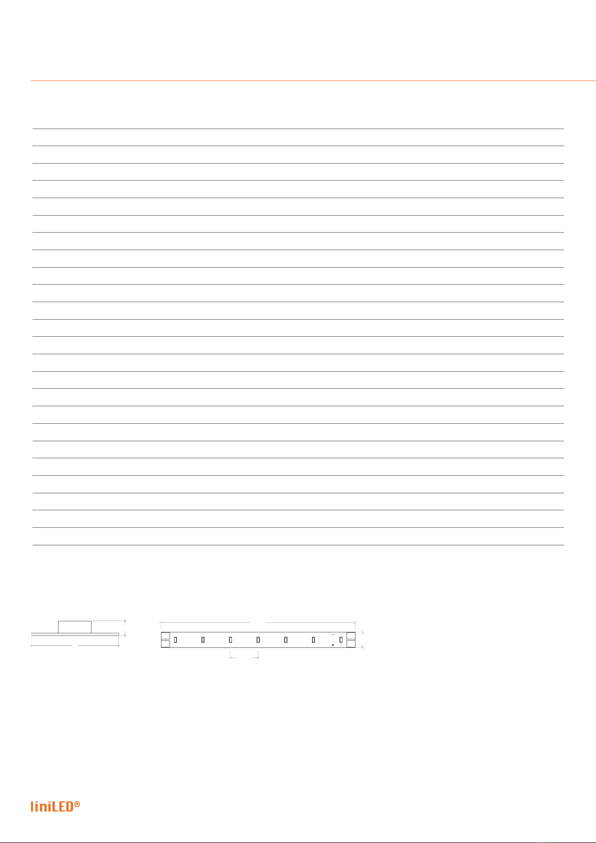
Product drawing
Extra Warm White
2700K D G1
Warm White
3000K D G1
Product code [m]
12430
12431
Power (24V DC)
1.6 W/m
1.6 W/m
Power (25V DC)
1.7 W/m
1.7 W/m
CCT
1
2750K
3065K
CRI
>80
>80
Luminous ux
1
190 lm/m
205 lm/m
Luminous eciency
1
119 lm/W
128 lm/W
Spool length
Max. 50 m
Section length
100 mm
LED type
3014
Number of LEDs
7 per section/70 per metre
Max. connection length
20 m
Min. operating voltage
23V DC
Max. operating voltage
25V DC
Beam angle
120°
Dimensions
8 x 1.4 mm
Dimmable
PWM dimming, 24V DC Common Anode
MacAdam Steps
3 steps
Weight
9 gram per metre
Expected lifetime
L80/B10 > 60,000 hrs @ Tc = 40°C
Ingress protection
IP00
Storage temperature
-40°C … 80°C
Operating temperature
2
-30°C … 75°C
Minimum bending radius
20 mm
1Typical values are given, which due to tolerances in components and production process can vary up to 10%.
2Max. connection length between -30°C and -20°C is 14 metres.
6
Manual | liniLED® PCB Mono White G1 & G4
Technical specications | Power G1
Extra Warm White
2700K P G1
Warm White
3000K P G1
Natural White
4000K P G1
Product code [m]
12435
12436
12437
Power (24V DC)
3.9 W/m
3.9 W/m
3.9 W/m
Power (25V DC)
4.1 W/m
4.1 W/m
4.1 W/m
CCT
1
2750K
3065K
4030K
CRI
>80
>80
>80
Luminous ux
1
480 lm/m
520 lm/m
520 lm/m
Luminous eciency
1
123 lm/W
133 lm/W
133 lm/W
Spool length
Max. 50 m
Section length
100 mm
LED type
3014
Number of LEDs
7 per section/70 per metre
Max. connection length
20 m
Min. operating voltage
23V DC
Max. operating voltage
25V DC
Beam angle
120°
Dimensions
8 x 1.4 mm
Dimmable
PWM dimming, 24V DC Common Anode
MacAdam Steps
3 steps
Weight
9 gram per metre
Expected lifetime
L80/B10 > 60,000 hrs @ Tc = 40°C
Ingress protection
IP00
Storage temperature
-40°C … 80°C
Operating temperature
2
-30°C … 75°C
Minimum bending radius
20 mm
1Typical values are given, which due to tolerances in components and production process can vary up to 10%.
2Max. connection length between -30°C and -20°C is 7 metres.
8
1.4
100
8
14.29
Product drawing

Manual | liniLED® PCB Mono White G1 & G4 7
50
8
8.33
Tc
Technical specications | High Power G4
Warm White
3000K HP G4
Natural White
4000K HP G4
Product code [m]
12253
12254
Power (24V DC)
7.0 W/m
7.0 W/m
Power (25V DC)
7.3 W/m
7.3 W/m
CCT
1
3065K
4030K
CRI
>80
>80
Luminous ux
1
800 lm/m
800 lm/m
Luminous eciency
1
114 lm/W
114 lm/W
Spool length
Max. 50 m
Section length
50 mm
LED type
3014
Number of LEDs
6 per section/120 per metre
Max. connection length
10 m
Min. operating voltage
23V DC
Max. operating voltage
25V DC
Beam angle
120°
Dimensions
8 x 1.4 mm
Dimmable
PWM dimming, 24V DC Common Anode
MacAdam Steps
3 steps
Weight
9 gram per metre
Expected lifetime
L80/B10 > 60,000 hrs @ Tc = 40°C
Ingress protection
IP00
Storage temperature
-40°C … 80°C
Operating temperature
2
-30°C … 75°C
Minimum bending radius
20 mm
1Typical values are given, which due to tolerances in components and production process can vary up to 10%.
2Max. connection length between -30°C and -20°C is 7 metres.
Product drawing
8
1.4
Product drawing

8
Manual | liniLED® PCB Mono White G1 & G4
1. Colour temperature 2700K | 3000K
2. LED strip length 1.0 m 5.0 m 10.0 m 20.0 m
3. Voltage 24 V DC 25 V DC 24 V DC 25 V DC 24 V DC 25 V DC 24 V DC 25 V DC
4. Cable cross section 0.50 mm - 0.035 Ω/m 192.4 m 370.6 m 37.4 m 73.0 m 18.0 m 35.9 m 8.4 m 17.3 m
0.75 mm - 0.023 Ω/m 289.4 m 557.5 m 56.3 m 109.9 m 27.2 m 54.0 m 12.6 m 26.0 m
1.00 mm - 0.018 Ω/m 384.8 m 741.2 m 74.9 m 146.1 m 36.1 m 71.8 m 16.8 m 34.6 m
1.50 mm - 0.012 Ω/m 578.8 m 1115.0 m 112.6 m 219.9 m 54.4 m 108.0 m 25.2 m 52.0 m
2.50 mm - 0.007 Ω/m 963.4 m 1855.7 m 187.5 m 366.0 m 90.5 m 179.7 m 42.0 m 86.6 m
Note: Calculations are based on a standard connector with 1 metre cable (0.5 mm).
1= Select colour temperature.
2 = Select LED strip length.
3= Select output voltage.
4= Select cable cross section.
Result = Maximum cable length based
on the cable thickness and power supply
voltage.
1
2
3
4
Result
Maximum cable length | Deco G1
Manual | liniLED® PCB Mono White G1 & G4 9
1. Colour temperature 3000K
2. LED strip length 1 m 2 m 5 m 10 m
3. Voltage 24 V DC 25 V DC 24 V DC 25 V DC 24 V DC 25 V DC 24 V DC 25 V DC
4. Cable cross section 0.50 mm - 0.035 Ω/m 78.1 m 151.2 m 38.4 m 75.0 m 14.6 m 29.2 m 6.6 m 13.9 m
0.75 mm - 0.023 Ω/m 117.6 m 227.5 m 57.8 m 112.8 m 21.9 m 43.9 m 10.0 m 21.0 m
1.00 mm - 0.018 Ω/m 156.3 m 302.5 m 76.8 m 150.0 m 29.2 m 58.4 m 13.3 m 27.9 m
1.50 mm - 0.012 Ω/m 235.2 m 455.1 m 115.6 m 225.6 m 43.9 m 87.9 m 20.0 m 42.0 m
2.50 mm - 0.007 Ω/m 391.4 m 757.5 m 192.5 m 375.5 m 73.1 m 146.3 m 33.3 m 69.9 m
Note: Calculations are based on a standard connector with 1 metre cable (0.5 mm).
1= Select colour temperature.
2 = Select LED strip length.
3= Select output voltage.
4= Select cable cross section.
Result = Maximum cable length based
on the cable thickness and power supply
voltage.
1
2
3
4
Result
Maximum cable length | Power G1

10
Manual | liniLED® PCB Mono White G1 & G4
Depending on the area where the liniLED® LED strip is installed we oer a range of solutions to cope with external factors. The product portfolio for the liniLED®
PCB LED strip includes an IP00 connector.
Indoor environment | (IP00)
Solder
Indoor environment | (IP00) | liniLED® PCB Connector Set
Product code: 11808
1. Colour temperature 3000K
2. LED strip length 1 m 2 m 5 m 10 m
3. Voltage 24 V DC 25 V DC 24 V DC 25 V DC 24 V DC 25 V DC 24 V DC 25 V DC
4. Cable cross section 0.50 mm - 0.035 Ω/m 42.9 m 83.7 m 20.8 m 41.2 m 7.5 m 15.7 m 3.1 m 7.2 m
0.75 mm - 0.023 Ω/m 64.6 m 125.9 m 31.3 m 62.0 m 11.3 m 23.6 m 4.7 m 10.8 m
1.00 mm - 0.018 Ω/m 85.9 m 167.4 m 41.7 m 82.4 m 15.1 m 31.4 m 6.2 m 14.4 m
1.50 mm - 0.012 Ω/m 129.3 m 251.8 m 62.7 m 124.0 m 22.7 m 47.2 m 9.4 m 21.7 m
2.50 mm - 0.007 Ω/m 215.2 m 419.2 m 104.4 m 206.3 m 37.9 m 78.6 m 15.7 m 36.1 m
Note: Calculations are based on a standard connector with 1 metre cable (0.5 mm).
1= Select colour temperature.
2 = Select LED strip length.
3= Select output voltage.
4= Select cable cross section.
Result = Maximum cable length based
on the cable thickness and power supply
voltage.
1
2
3
4
Result
Maximum cable length | High Power G4

Manual | liniLED® PCB Mono White G1 & G4 11
Depending on the area where the liniLED® LED strip is installed we oer a range of solutions to cope with external factors. The product portfolio for the liniLED®
PCB LED strip includes an IP00 connector.
Indoor environment | (IP00)
Solder
Indoor environment | (IP00) | liniLED® PCB Connector Set
Product code: 11808
Area advice

12
Manual | liniLED® PCB Mono White G1 & G4
20 mm
20 mm
Maximum bending radius is 20 mm. Solely bend up or downward. Do not compress or stretch the LED strip.
Do not bend the LED strip sidewards. Do not twist the LED strip.
The LED strip has to be unreeled on a horizontal surface at the time of installation. Do not unreel the spool of LED strip before installation.
Product care and handling

Manual | liniLED® PCB Mono White G1 & G4 13
Work in an ESD protected environment. Make use of an anti-static
strap.
Turn o the power before cutting the LED strip.
Top view | Only cut on the dotted lines to prevent damaging the
LED strip.
Cutting instructions

14
Manual | liniLED® PCB Mono White G1 & G4
Work in an ESD protected environment. Make use of an anti-
static strap and use lead-free solder.
Turn o the power. Make sure the wires are not under electric
current.
0.5 mm
2
8 mm
300°C
Max. 4 sec.
We advise to use a cable with an area not larger than 0.5 mm2. Pre-solder the connector pads.
300°C
Max. 4 sec.
Pre-solder the wires. Solder the wires to the connector pads.
Solder

Manual | liniLED® PCB Mono White G1 & G4 15
Connect IP00
Open the PCB connector. Push the liniLED® PCB LED strip into the connector. Make sure the
polarity is correct and the connection pads are facing up.
Close the PCB connector.

16
Manual | liniLED® PCB Mono White G1 & G4
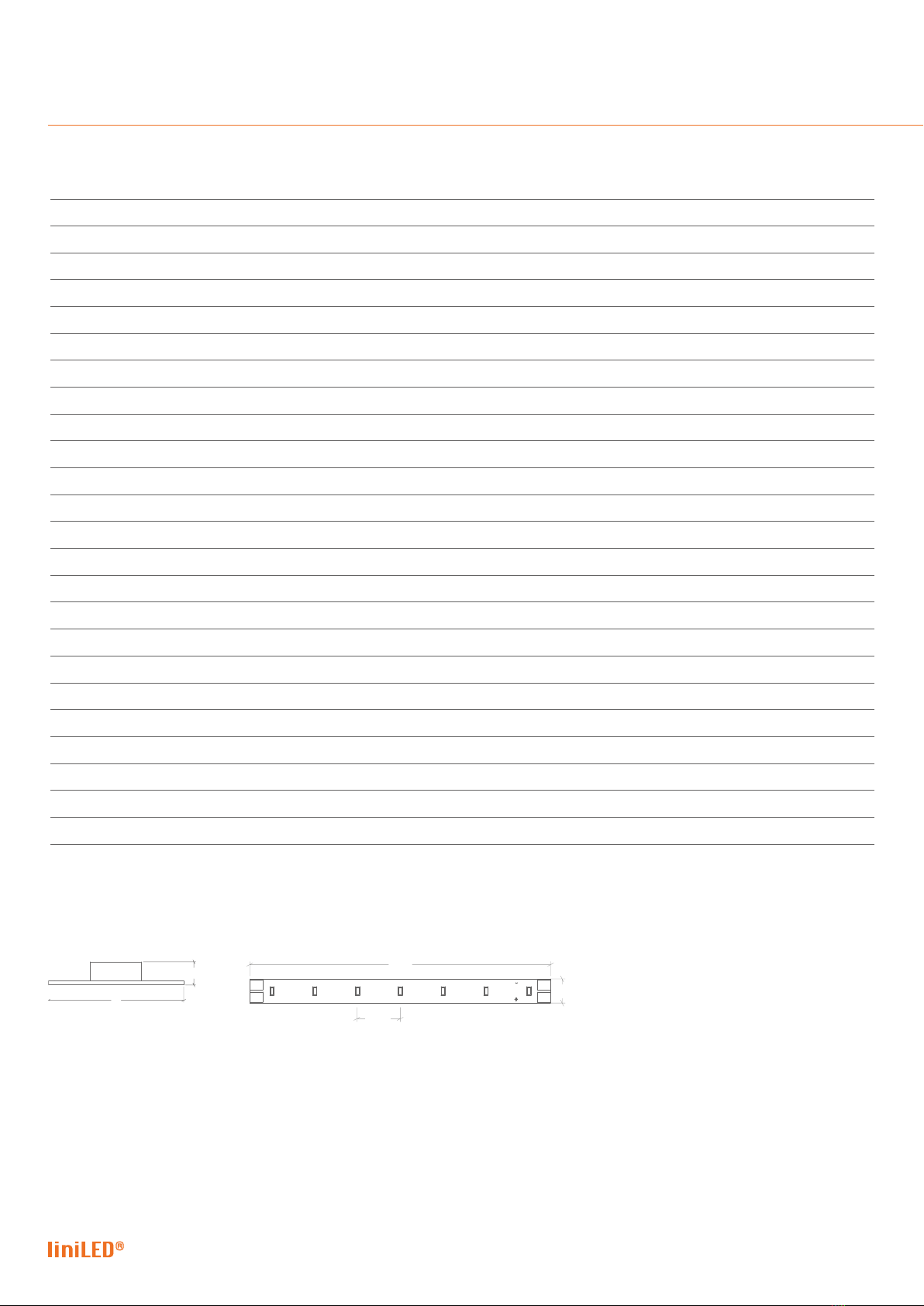
Power and connection diagram
Turn o the power. Make sure the wires are not under electric
current.
liniLED® Control
(Optional)
L
NPower
Supply
24 V
DC -
+
230 V
AC
-
+
-
+
-
+
Measure output (23 - 25V DC)
before installing liniLED® system
Manual | liniLED® PCB Mono White G1 & G4 17
Disclaimer
The published information is checked to be as accurate as possible, however Triolight B.V. or any reseller of liniLED® cannot be held liable for any damages resulting
from misprints, errors, modications or outdated information. No legal rights can be derived from this document. Triolight B.V. reserves the right to modify the
information without informing the customers. Please check for the latest version on www.liniLED.com. This product should not be used in applications, devices or
systems where incorrect operation of the product may result in personal injury (includes emergency lighting) without written permission from the board of Triolight
B.V. If nevertheless used in such applications, devices or systems,Triolight B.V. cannot be held liable for any resulting injury. liniLED® is a registered trademark of
Triolight B.V.
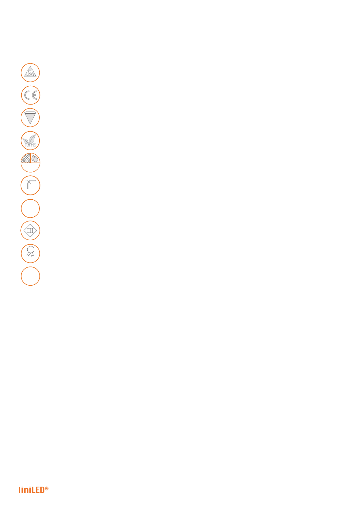
Electro Static Discharge (ESD) sensitive device, apply standard ESD precautions when handling the product.
Not protected against ingress of solid foreign objects. Not-protected against ingress of water.
IP00
IP00
FSuitable for mounting on all surfaces and suitable to cover with insulating material.
Manufacturer’s declaration that the product meets the applicable EC directives.
Bending of the LED strip is possible with a radius of ≥ 20 millimetres in the specied direction.
BEND RADIUS
R
20 mm
RoHS
Restriction of Hazardous Substances (RoHS): product complies with the RoHS directive and each homogeneous material does not exceed
the limits for the materials mentioned under the RoHS directive (Pb, Hg, Cd, Cr6+, PBB and PBDE).
5
5
System
System guarantee of 5 years when the complete system consist of liniLED® products with the 5 years system warranty logo.
Terms & conditions apply.
MAC
ADAM
2
S D C M
White colour consistency up to 2 SDCM ellipse over an entire single strip length. LEDs used are single BIN 3 SDCM ellipse, but their careful
combination in a LED strip during the production process, results in a mixed light through a diusive material which is within a 2 SDCM ellipse
(probability >90%). Due to variability this is not legally binding. The guaranteed colour consistency can be found in the technical specications.
Symbols
Electrical appliance class III: this product is designed to be supplied from an extra-low voltage (≤ 60.0 V DC or ≤ 42.4 V AC).
Operating voltage of 24 V DC.
24
24
V D
C


V301220
Other manuals for PCB Mono White G1 Series
1
This manual suits for next models
15
Table of contents
Other liniLED Outdoor Light manuals

Popular Outdoor Light manuals by other brands


Beurer
Beurer TL 90 Instructions for use

LIGMAN
LIGMAN AU-30601 installation manual

Sea gull lighting
Sea gull lighting 1 Light Outdoor Wall 8301 Series installation instructions

Knightsbridge
Knightsbridge GDL2 Installation & maintenance manual

Unex
Unex 160-091-70 operating manual

MIMSAL
MIMSAL MS user manual


