Link CAN Gauge User manual

CAN GAuGe
USER MANUAL
Part No. 101-0226

Box CoNteNts
• 1 x Link 52mm CAN Gauge
• 1 x Mounting bracket with thumb screws
• 1 x 5’ (152cm) Connection Cable Terminated to DTM-4
• 1 x DTM-4 Mating Connector Kit
• 2 x Link Stickers
tABle of CoNteNts
Introduction . . . . . . . . . . . . . . . . . . . . . . . . . . . . . . . . . . . . 1
Requirements & Gauge Mounting . . . . . . . . . . . . . . . 2
Link CAN Bus Connection . . . . . . . . . . . . . . . . . . . . . . 3
Terminating Resistor Configuration . . . . . . . . . . . 3-4
Illumination Signal Wiring . . . . . . . . . . . . . . . . . . . . . . 5
Connect to gaugeART CAN Gauge App . . . . . . . . . 5
Create Configuration . . . . . . . . . . . . . . . . . . . . . . . . . . . . 6
Save & Send Configuration . . . . . . . . . . . . . . . . . . . . . . 7
Load Configuration . . . . . . . . . . . . . . . . . . . . . . . . . . . . . 7
PC Link CAN Stream Configuration . . . . . . . . . . . . . 8
For extended channels . . . . . . . . . . . . . . . . . . . . . . 9-10
Troubleshooting & Support Contact . . . . . . . . . . . . 10
INtro to the 52mm CAN GAuGe
The Link CAN Gauge is a compact 52mm OLED gauge that connects
to Link G4+/G4X ECUs* to display real-time data from CAN broadcasts.
No sensors are added to the gauge – all gauge data is sent from the
ECU over the CAN network. The gauge is wirelessly configurable using
an Android or Apple iOS mobile device through Wifi. Gauge channels,
bar graphs, warning points, and custom gauge labels can be configured
using the CAN Gauge App.
* Works with any CAN enabled Link ECU. Check with Link Tech Support
team if you are unsure of compatibility.
requIremeNts
• Smartphone or Tablet: Smartphone or tablet with Apple iOS or
Android v4.4 or later.
• CAN Enabled Link ECU (G4+ onwards).
GAuGe mouNtING & CABle
INstAllAtIoN:
• Remove the supplied mounting bracket from the rear of the gauge by
unscrewing the two thumb screws from the rear of the gauge.
• The gauge is sized for a 2-1/16” or 52mm mounting hole. Use the
mounting bracket to secure the gauge in place.
• Plug in the supplied cable to the rear of the gauge. Either one of the
two connectors may be used.
• If using more than one Link CAN Gauge, join the two gauges using the
optional daisy chain cable (part no. 101-0227). The last gauge in the
chain will only be connected with the daisy chain cable.
1 2

lINk CAN Bus CoNNeCtIoN
The Link CAN Gauge includes a CAN connection cable that is
pre-terminated to a DTM-4 connector. There is also a mating
DTM-4 connector kit included in the box. Use this connector kit to wire
into your vehicles CAN bus Pin out is shown below.
DTM-4 Mating
Connector Kit Pinout CAN Gauge Side
DTM-4
11
2233
4411
2233
44
Pin Number Colour Typical Application
Pin 1 Red Ignition switched +12v (5 amp fused)
Pin 2 Black Chassis Ground
Pin 3 Green CAN Low
Pin 4 White CAN High
Flying Lead Orange +12V Illumination Power
termINAtING resIstor
CoNfIGurAtIoN:
• The Link CAN Gauge includes a user-configurable 120 ohm
terminating resistor jumper. The resistor is enabled when the jumper is
in place.
Rear of Gauge
Terminator
• CAN networks require a 120 ohm resistor on the ends of the network
– one at the ECU, and one on the last device in the network (see
image below for an example). Leave the terminating resistor jumper in
place if the CAN Gauge is the last device in the chain of CAN devices.
Remove the jumper if there are already two terminating resistors at the
ends of the network (see below for an example).
• All Link G4+/G4X ECU’s have a 120 ohm terminating resistor fitted
• Having too many or not enough resistors can cause the gauge or other
devices to malfunction.
CAN GAuGe
120 ohm Resistor
ECU with built in
120 ohm Resistor
CAN GAuGe CAN GAuGe
ECU with built in
120 ohm Resistor
120 ohm Resistor
Example of two CAN networks – 120 ohm resistor must be on the last
device in the chain. 43

CreAte CoNfIGurAtIoN:
• Tap Create Configuration. Select ECU type and tap Next.
• The gaugeART CAN Gauge allows you to create up to 10 pages
of gauge layouts in 1, 2, or 4 gauge layouts. Tap the center of the
screen for Gauge Screen Setup. On this screen, select a channel,
configure graph range, update speed, warnings, and gauge labels
(e.g. rename “MAP” to “BOOST”).
• Tap Previous Page to return.
• Tap the left side to change the configuration between 1, 2, or 4
gauge layout.
• Tap Next Page to add a new page or delete to remove a page.
IllumINAtIoN sIGNAl WIrING:
• The Link CAN Gauge can dim illumination during night when the
parking lights are on. Using the factory service manual, find a wire in
the interior that switches to +12V power when the parking lights are on.
Verify with a voltmeter or test light that the wire receives +12V when
the parking lights are turned on.
• The connection cable provides a separate orange unterminated wire
for +12V illumination power
• Note that some vehicles, including many Hondas, have an illumination
switched connector in the interior fuse box.
• Depending on access to the wire – use a wire tap or splice the factory
wire to connect the gaugeART CAN Gauge orange wire.
CoNNeCt to CAN GAuGe App:
• Search “gaugeART” and download the gaugeART CAN Gauge App
from your device’s app store.
• If you have two Link CAN Gauges, they can be programmed
separately.
• Turn on your ignition to turn on Link CAN Gauge. The welcome screen
will be shown.
• Connect to the gauge via Wi-Fi by tapping on settings > Wi-Fi.
• Tap on gaugeART and enter the default password “12345678”. Allow
the gauge to connect. If prompted with a message that internet is not
available with this device, tap ok.
• You may now open the gaugeART CAN Gauge App.
5 6
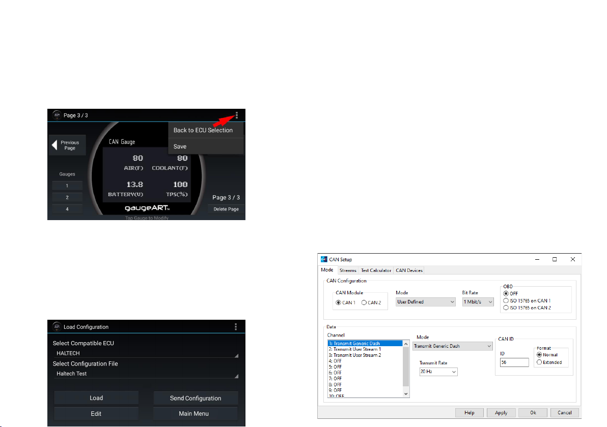
sAve & seNd CoNfIGurAtIoN:
• Tap the icon in the top right and tap Save.
• Enter a name under “Enter Save File Name” and tap Save.
• To program, tap Send Configuration. The gauge will be programmed
and will show your configuration. Programming takes anywhere from
10-60 seconds and will update the gauge’s firmware automatically if
an update is available.
loAd CoNfIGurAtIoN:
• Select the ECU you are working with.
• Previously saved files will be shown in the second drop down. Click
load to open the file.
• To Edit your saved configuration, tap edit once loaded.
• To program, tap Send Configuration.
pClINk CAN streAm
CoNfIGurAtIoN:
• Open PCLink
• Open the CAN Setup window > ECU Controls > CAN Setup).
• Select the CAN module to be used.
• Set the Mode to ‘User Defined’.
• Configure the Bit Rate to 1 Mbit/s
• Select a spare CAN channel.
• Select ‘Transmit Generic Dash’ from the Mode drop-down menu.
• Set the CAN ID to 56.
• Set the Transmit Rate to 20Hz.
• Set the Format to Normal.
• Click Apply and then OK.
• Make sure a Store (F4) is performed.
7 8
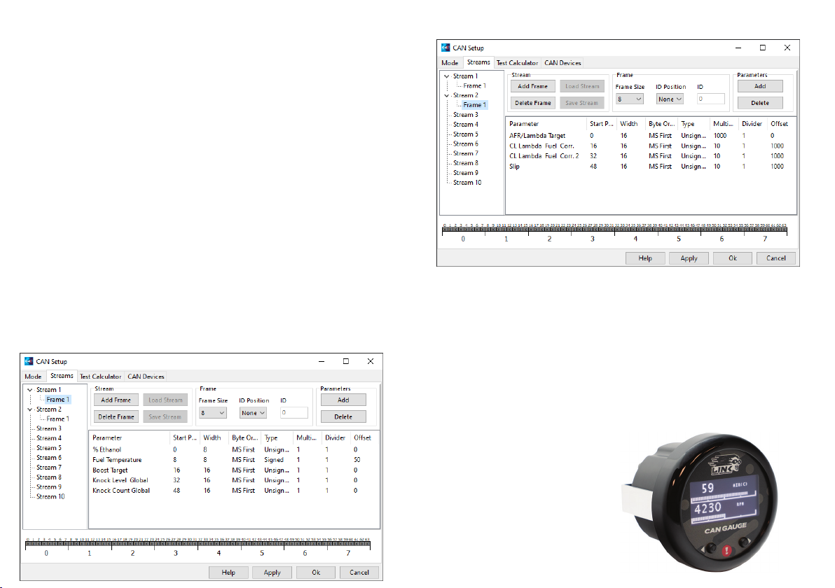
for exteNded ChANNels:
• Select another spare CAN channel.
• Set Mode to “Transmit User Stream X” (Where X is the next unused
transmit or receive user stream number).
• Set CAN ID to 50.
• Set Transmit Rate to 20Hz.
• Set Format to Normal.
• Change to the Streams tab of the CAN Setup window.
• Select Stream X and then click Load Stream.
• Select ‘GaugeART_CAN_Gauge_Extra_ID50.lcs’ and click the Open
button (find this in the CAN folder of your PCLink install).
• Change back to the Mode tab, select the next spare CAN channel.
• Repeat steps1-7 for the ‘GaugeART_CAN_Gauge_Extra_ID51.lcs’ file,
this time using the CAN ID 51.
• Click Apply and then OK.
• Make sure a Store (F4) is performed.
PCLink Extended CAN Channels 1
PCLink Extended CAN Channels 2
trouBleshootING:
• App says gauge is not connected: connect gauge in Wi-Fi settings
before opening app. Make sure Wi-Fi is connected (a checkmark
appears when connected). Make sure to give app permission to use
Wi-Fi if prompted.
• Gauge stays in Programming Mode: the gauge will stay in
programming mode until a configuration is sent.
CoNtACt us:
• info@gaugeART.com
9 10

lINk eNGINe mANAGemeNt
hAve A rANGe of
ACCessorIes to help You
truelY uNleAsh the
poteNtIAl of Your eNGINe!
Part No. 101-0226
This manual suits for next models
1
Table of contents
Other Link Accessories manuals


