Link PJ7rmn5068a Quick guide
PJ7 Headset Interface
Configuration and Installation Manual
Link Communications, Inc.
1035 Cerise Road
Billings, MT 59101
(406) 245-5002
www.link-comm.com

Introduction:
Congratulations on purchasing the LinkTDS PJ7 dispatch headset interface. This powerful
interface will provide quality audio, ease of operations and support for multiple PTT interface
formats. The technology is designed for a rugged environment yet carefully designed to fulfill
any dispatch environments audio needs.
Installation:
The LinkTDS PJ7 (PJ7) interface plugs into any computer that supports a USB sound interface
via the systems USB port. To operate the PJ7 simply plug into the computers USB port and the
unit is ready to operate.
Note:
A front panel USB port is brought out to replace the port used for the PJ7 and can be used for
any USB device such as a thumb drive, USB mic/headset or USB based peripheral.
When plugged in the computer will recognize several devices that are located inside the PJ7.
1. USB Soundcard interface
a. This device provides the PJ7's audio support for the earphone and microphone
2. FT232 Serial Port
a. This device provides the computer an ability to customize the PJ7's settings for
each setting. The settings are volatile therefore they will need to be set-up by your
software each time. When ordering additional PJ7's Link will happily set-up
defaults for your PJ7's. When power is then applied, your settings will be recalled
requiring no customization from your software.
b. The volatile nature of the settings was designed to associate each user with their
own mic/volume settings. Therefore when a user logs on to the CAD software the
software can tell the PJ7 what settings are associated with the operator.
3. USB Hub
a. This device is needed to convert your 1 USB port into several USB Ports
4. Macroworks Interface
a. This device provides the HID support for custom Push To Talk support in your
dispatch software. You will need to assign the necessary keyboard keystrokes to
simulate a PTT on and a PTT off. You will need to run a configuration software
on a Windows(TM) computer to configure the keystrokes and to FLASH them
into the PJ7's non-volatile memory.
These interfaces enable the PJ7 to be configured and to operate. Special drivers may be needed
and are included on the enclosed disk.
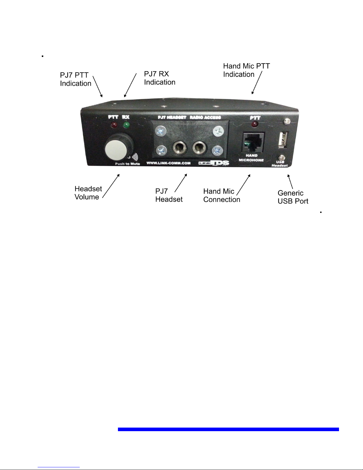
Front Configuration:
PJ7:
When using the PJ7 you need to use a 6-wire headset that supports PTT on the wiring harness. If
you prefer to use a foot pedal the connections are located on the back. Plugging in the headset
causes a keyboard event as well as unplugging it causes a different event. Se Event
Configuration for more specifics.
PJ7 PTT has a keyboard event associated with it as well as unkeying the PTT
Headset Volume:
The headset volume only controls the volume in the headset. The external speaker volume is
pre-volume level (fixed) UNLESS you configure it differently. If configured as post volume,
then front panel volume affects the external volume.
The computer volume will affect the volume of the PJ7. If reconfigured, the volume level will
control the computers volume up/down (the same as the keyboard does). As default, the volume
control is internal to the PJ7 and will not control the computers volume.
It is recommended that you adjust the computers volume level to the loudest you will ever want
the volume in the headset, then do your adjusting from the PJ7's volume level.

Hand Microphone Connection:
If you have a desk mic and choose to use it and not the PJ7 headset for your dispatch position, or
both, plug in an appropriate desk or hand “potato” microphone. The connector is configured to
accept any Motorola(TM) RJ45 connector based accessory mic’s (Motorola # RMN5068A).
These microphones are available from Link Communications. It’s PTT function is different from
the PTT of the PJ7, and contains its own separate mic level configuration.
Generic USB Port:
This port is one connection from the internal USB hub. It can be used for any USB based device.
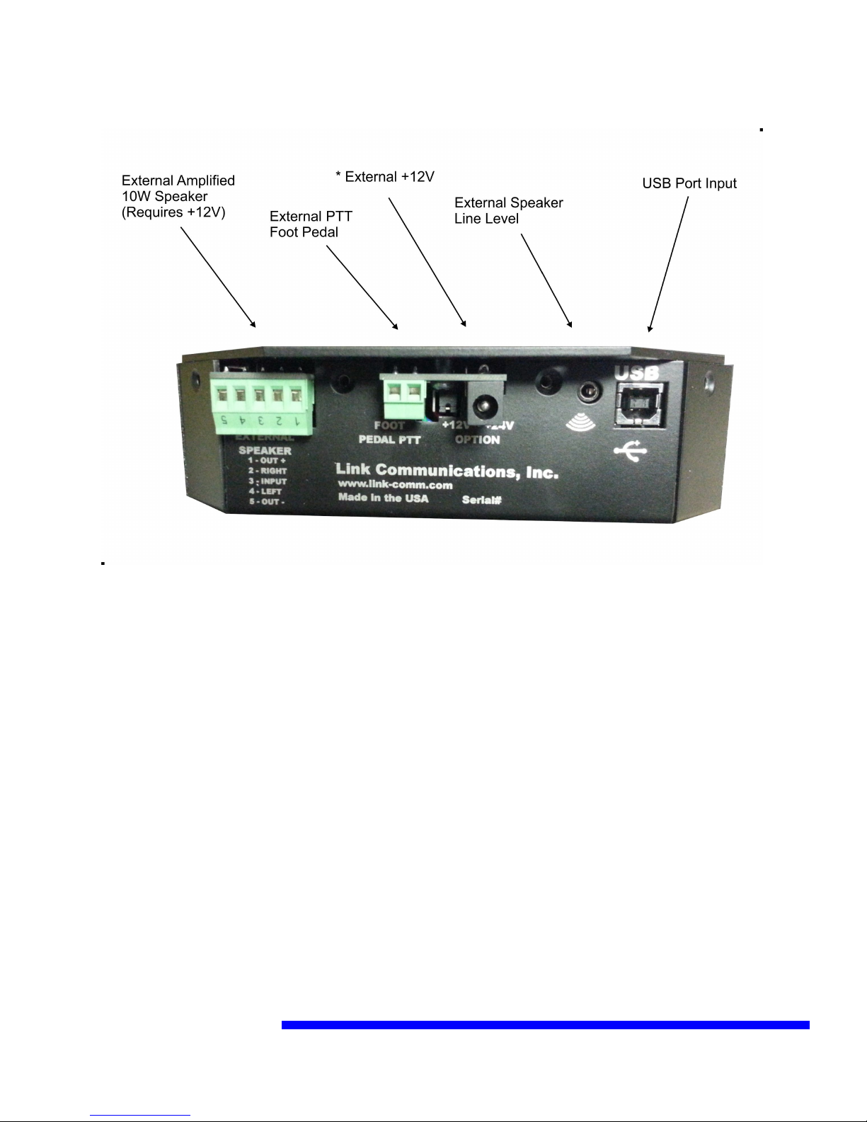
Back Configuration:
USB Port:
This connection is used to connect the PJ7 to the computer running your CAD software. A USB
cable is included with the PJ7 module. Power is provided from the computers USB port so
external powering is not necessary unless running the 10W powered speaker output.
External Speaker Line Level Output:
The external line level audio output is designed to feed a self-powered speaker, such as computer
speakers. It is a stereo output and can be configured as either Per-volume or post-volume. If pre-
volume then adjustments from the front volume control will not affect the speakers level. If
post-volume then it follows the front volume adjustment. The configuration is covered in the
next section.
This output is not intended to directly drive a speaker, it is a low-level line level output.
External +12V:
The external +12V power jack is used when utilizing the internal +10W speaker output. If using
external power you will need to move the internal/external power jumper (located directly behind
the power jack) and apply a center positive power supply. The power supply will need to be
rated at 3A to handle the audio level out the speaker.

External Foot Pedal:
When using an external foot pedal PTT accessory you will need to connect the pedal to this
connector. Polarity is not an issue, simply attach a contact closure when pushed pedal to this
input. Contact Link Communications for availability.
Audio input is routed from the PJ7 when using the external foot pedal, custom routing can be
changed based on need, contact Link Communications for details.
External 10W power speaker:
The PJ7 provides a powered speaker output that can be either Left or Right channels. When
operating the speaker you will need to attach an external +12V power supply with a 2.5mm
center pin positive supply with a current rating of 3A minimum
It is a mono output and can be configured as either Per-volume or post-volume. If pre-volume
then adjustments from the front volume control will not affect the speakers level. If post-volume
then it follows the front volume adjustment. The configuration is covered in the next section.

Custom Configuration Commands:
The PJ7 interface has an internal USB based configuration serial port to enable customization of
settings. The settings are volatile and default to factory defaults when power is interrupted. The
purpose of the commands is to allow the CAD software to make custom changes to the PJ7 based
on the logged on operator therefore defaults are overwritten by the CAD software when it starts.
If necessary Link can default purchased units to contain the customers preferred settings on
power-up, contact Link Communications for details.
Serial Port:
Baud: 19,200
Handshaking: None
Stop Bits: One
Parity: None
Refer to your Device Manager for the correct COM port the reference
Commands:
To make sure you are communicating out the correct COM port, hit the ENTER key and you
should get the “PJ7>” prompt on the screen.
To enter a serial command start with an open-bracket ‘[ ‘ followed by the command number and
terminated with a closed-bracket ‘]’.
For example, I want to see what the settings are, so I enter the interrogate command ‘0': [0]
The result appears:
PJ7>[0]-----------------------------------------
PJ7 Microphone Level: 005
Hand Microphone Level: 010
Volume Configuration: X=0:Y=0:Z=0
Initial Volume Level for PJ7 Headphones: 128
Initial Volume Level for Line Out: 128
Lower Limit for Headphone Audio: 005
Upper Limit for Headphone Audio: 250
Lower Limit for Line Out Audio: 005
Upper Limit for Line Out Audio: 250
-----------------------------------------

This readout indicates the settings of the PJ7. To make a change you will need to enter one of
the commands to manipulate the interface. The commands have a specific format and must be
followed otherwise the command will not execute.
Commands:
0 - Recall the settings of the PJ7 Format: [0]
1 - Set the PJ7 Microphone Level from 00 - 99 Defaults: 05
Format: [1 xx] where xx ranges from 00 to 99
2 - Set the Hand Microphone Level from 00 - 99 Defaults: 10
Format: [2 xx] where xx ranges from 00 to 99
3 - Configure Volume Control Actions: Defaults: 0, 0, 0
Format: [3 x y z] where
x = 0: Speaker output is Pre-Volume Pot, non-adjustable volume
x = 1: Speaker output is Post-Volume Pot, adjustable volume
y = 0: Volume is controlled from the PJ7 internally
y = 1: Volume is externally controlled from USB HID commands
z = 0: Headphone Mute is handled internal to the PJ7
z = 1: Headphone Mute is controlled from USB HID commands
4 - Initial Volume for the PJ7 Headset: Defaults: 128
Format: [4 xxx] where xxx ranges from 000 to 255
5 - Initial Volume for the Line-Out/Speakers: Defaults: 128
Format: [5 xxx] where xxx ranges from 000 to 255
6 - Minimum volume level for the PJ7 Headset: Defaults: 005
Format: [6 xxx] where xxx ranges from 000 to 255
7 - Maximum volume level for the PJ7 Headset: Defaults: 250
Format: [7 xxx] where xxx ranges from 000 to 255
8 - Minimum volume level for the Line-Out/Speaker: Defaults: 005
Format: [8 xxx] where xxx ranges from 000 to 255
9 - Maximum volume level for the Line-Out/Speaker: Defaults: 250
Format: [9 xxx] where xxx ranges from 000 to 255
A - Reset settings to defaults Format: [A YES]
This command will reset all values to defaults which is the same as a Power-up Condition

Custom Keyboard Commands:
The PJ7 utilizes a third party device that simulates USB HID commands based on contact
closures to report activity on the PJ7 to your CAD software. The keystrokes that are sent from
the PJ7 can be fully customized by the users and/or the CAD software company.
Each input has a “Pressed” and a “Released” event that may need to be assigned. Each event can
contain a sequence of keystrokes, mouse clicks and joystick actions.
If a sequence in not supported then contact Link Communications for assistance.
HID programmable events:
PJ7 headset plugged in and PJ7 headset unplugged (one line with two events)
PTT just pressed and PTT just released (one line with two events)
Volume Up (one line with two events)
Volume Down (one line with two events)
Mute pushed and Mute released (one line with two events)
Installing MacroWorks:
On the enclosed disk is a program used to set-up the necessary keystrokes for the PJ7 interface.
Installing the program on the dispatch CAD computer is not necessary, it is only needed on a
computer that can be used to initialize the PJ7 is all that is needed.
Once installed a Quick Launch Icon is generated and placed on your toolbar. Double
click the icon to launch the configuration software.
Note: The software will not launch is the PJ7 is not plugged into the USB port.
Assignments:
R1, C1: Volume Down
R2, C1: Volume Up
R3, C1: PTT Active/Inactive
R4, C1: PJ7 Plugged In / Unplugged
R5, C1: Mute Button Pressed/Released
Note: You must have focus on the software for it to sense a line change event. Click on the
MacroWorks window to gain focus.
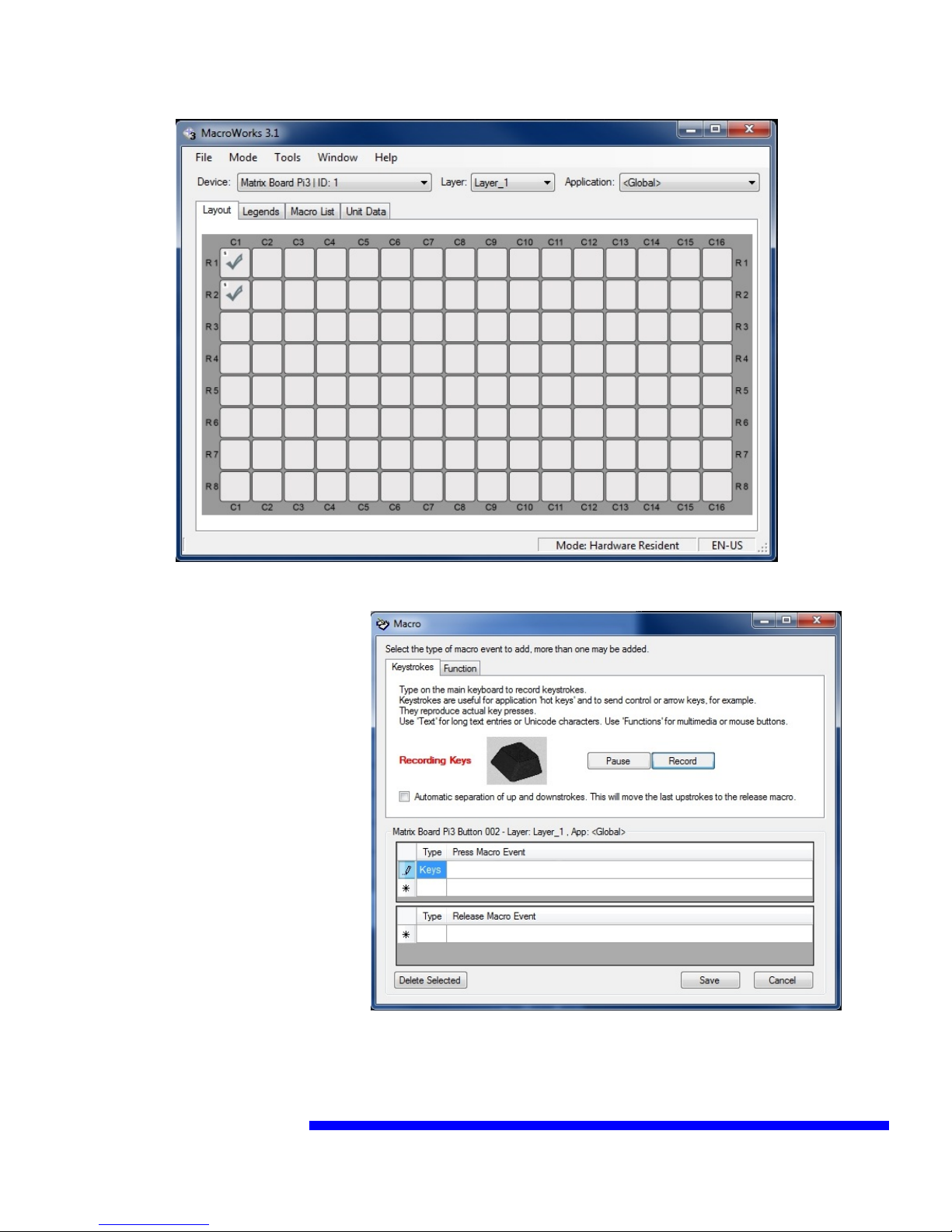
Settings:
Mode: Hardware Resident Mode
Steps:
1) File, Read Device: This reads
the setting already programmed
into the module
2) Cycle the input you need to
assign, for example turn the
volume pot one click and the
software will provide you an
assignment screen
3) Assign Keystrokes by typing
on the keyboard (you will see the
keystrokes) or click function to
access non-keyboard functions
from Mice and Joystick devices.
When completed Click Save,
4) Once completed assigning all your keystrokes, click on File, Write to Device.
5) You can now disconnect and use the device, it is programmed and ready.

Technical Support:
support@link-comm.com
Software Updates:
http://link-comm.com/index.php/site/support
Click on LinkTDS PJ7 Software
Link Communications, Inc.
1035 Cerise Road
Billings, MT 59101
(406) 245-5002
www.link-comm.com

Appendix: Schematic Diagrams
Other Link Accessories manuals

Popular Accessories manuals by other brands


Somogyi
Somogyi home AD 30 instruction manual

lifeCharge
lifeCharge JuicyBar user manual

Neptronic
Neptronic SAR24GH Specification and installation instructions

Transparent
Transparent POWERBANK 1 owner's manual

LEGRAND
LEGRAND Wattstopper LMDW-101 quick start guide

Nice
Nice TCB65 Instructions and warnings for the fitter


