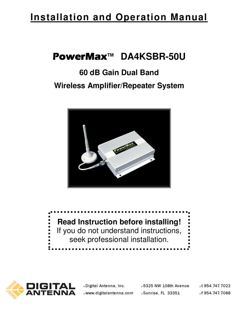
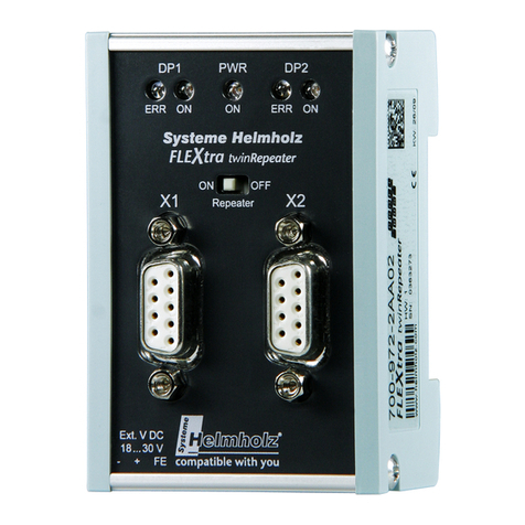
Link RLC-2 User manual

RLC-2 Repeater and Linking Controller
Software Version 3.06
Copyright 1995 All Rights Reserved
Link Communications Inc.
P.O. Box 1071
Sidney, MT 59270
(406) 482-7515

Copyright 1995 Link Communications Inc.
Introduction:
Congratulations, you have purchased a very powerful tool for your group's repeater. The
RLC-2 may seem complicated and intimidating at first, but don't worry. Setting it up and
programming it are easy and straightforward, once you have read the manual. Please take the
time to read it before you try to start programming. This will save you a lot of confusion and
frustration, as it should answer most of your questions.
The RLC-2 repeater controller consists of one repeater port, two linking ports, four analog
voltage inputs, four logical (dry contact) inputs, and eight MOSFET output drivers. The
repeater port and each of the linking ports can be configured to require one of several
combinations of COR and PL inputs for access. The RLC-2 has a single DTMF decoder that
scans between the three receiver ports, thereby supporting DTMF control from all ports of the
controller. Synthesized voice prompts the users in the programming of the controller's
variables, provides voice ID's and alarms based on the inputs, etc.
This manual consists of three main sections: setup and interfacing, programming and
commands, and the appendices with commonly referenced tables and charts. A glossary has
also been included at the end to explain some of the terms and abbreviations that are used
throughout the manual.
We have attempted to explain everything in a way that is easy to understand, but some
questions are inevitable. If you have carefully read the manual and still have questions, call
or us at (406) 587-4085 or Fax us at (406) 585-7575 write to us at
Link Communications Inc.
P.O. Box 1071
Sidney, MT 59270

Copyright 1995 Link Communications Inc.
LIMITED WARRANTY
COVERAGE:
Link Communications warrants that its products will be free from defects in materials and
workmanship for a period of one year from the date of shipment. During this time, Link
Communications will cover parts, labor and return shipping. If failure is caused by instances
other than manufacturing defects, Link Communications will repair the product and bill the
customer for parts and labor. Contact Link Communications for more information.
What Link Communications will not cover:
1. Too much voltage to the controller. The RLC-2
operates at +11V to +15V, negative ground.
2. Damage to the controller by lightning, accident, or
incorrect power hook-up.
3. Incorrect unit installation.
4. Damage caused by shipment (damage claims are handled
by the carrier).
6. Repairs by other than Link Communications.
THIS WARRANTY HOLDS ONLY TO THE ORIGINAL PURCHASER
HOW TO GET SERVICE
Please contact Link Communications for servicing information and authorization.
SOFTWARE
Link Communications holds the copyright on the RLC-2's software and hardware. Changes
to the software, copying of the software, and use of the voice code is prohibited without the
written consent of Link Communications.
SOFTWARE UPDATES
Link Communications will provide FREE Software updates for 6 months from the date of
purchase. The owner must return replaced software chips to Link Communications in order to
obtain further software updates. Software updates will cost $50.00 after the update warranty
expires. Manual inserts and shipping are additional.

Copyright 1995 Link Communications Inc.
User Survey (Optional)
A knowledge of the user base will allow us to better serve you in the future by helping us
develop more specialized software and hardware. Please take a few minutes and fill out this
questionnaire.
RLC-2 Serial Number ................. ________________
RLC-2 Purchase Date ................. ________________
Application: (Circle All That Apply)
Ownership:
- 1 - Privately Owned Repeater
- 2 - Club Owned Repeater
- 3 - Group Owned Repeater
- 4 - Commercial Business Repeater
- 5 - Other _______________________
Installation:
- 1 - Wide Coverage Repeater with Chain Links
- Port to Port Linking
- 2 - Full Duplex Links
- 3 - Half Duplex Links
- 4 - VHF Repeater: Power _____ Make ____________
- 5 - UHF Repeater: Power _____ Make ____________
- 6 - Link Ports Used as Repeater Ports: Yes No
- 7 - Serial Data Used to Control Repeater: Yes No
- 8 - Other Amateur Repeaters At the Site: Yes No
- 9 - Other Link Communication Products Used: Yes No
Misc:- 1 - User Base: Technical Rag Chew Personal
- 2 - Autopatch used on the System: Yes No
- 3 - Frequency Adjustable Remotes: Yes No
- 4 - Linking to Other Repeaters: Yes No
- 5 - Linking Closed Access: Yes No
- 6 - PL Required on Main Repeater: Yes No Varies
- 7 - PL Required on Linking System: Yes No Varies
Please Return to: Link Communications
P.O. Box 1071
Bozeman, MT. 59771
Comments:

Copyright 1995 Link Communications Inc.
Table of Contents
Getting On The Air Quickly ................................................. i
Setup and Interfacing ....................................................... 1
Serial Port Interfacing ...................................................... 5
RLC-2 Command Entry Format: .............................................. 7
Software Resistors and their Applications ...................................... 13
Analog ExamplesLogical Latched Output Lines ................................. 16
Logical Input Line ........................................................ 17
Analog Input Telemetry Lines ............................................... 18
Programming and Commands ............................................... 19
A Brief Description on how to use: Macros ..................................... 20
A Brief Description on how to use: Drop-Out Messages ........................... 21
A Brief Description on how to use: Lack of Activity Timers ........................ 22
A Brief Description on how to use: Scheduler ................................... 23
A Brief Description on how to use: Remote Base Functions ........................ 24
A Brief Description on how to use: Audio Routing Variables ....................... 25
A Brief Description on how to use: Analog Input Alarming ........................ 26
A Brief Description on how to use: Input Line Alarming .......................... 27
Command Listing (by function) .............................................. 28
Analog Alarming, Uses and Limitations ....................................... 33
Command Listing (by name) ................................................ 40
In Depth Command Description: C000..C011
Port Configuration .................................................. 45

Copyright 1995 Link Communications Inc.
In Depth Command Description: C012 - C014
Main, Link 1 and Link 2 Repeater or Link port Configuration ................ 46
In Depth Command Description: C015 - C017
Main, Links 1 and Link 2 Time Out Timers Enabled/Disabled ................ 47
In Depth Command Description: C018 - C020
Set-up Main, Link 1 and Link 2 Access modes ............................ 48
In Depth Command Description: C021 - C023
Supervisory PTT control for Main, Link 1 and Link 2 ....................... 49
In Depth Command Description: C024 - C027
Link 1 and 2 Lock/Unlock ............................................ 50
In Depth Command Description: C028 - C029
Remove Links 1 and 2 From System with DTMF Still Enabled ............... 51
In Depth Command Description: C030 - C031
Enable Links 1 and 2 on the System .................................... 52
In Depth Command Description: C032 - C034
Repeater ON/OFF/MON the Link System ................................ 53
In Depth Command Description: C035 - C036
Repeater COR Access or Repeater CAP Access ........................... 54
In Depth Command Description: C037
Voice Response Polite/Impolite Switch .................................. 55
In Depth Command Description: C038
COR Command Execution ON/OFF .................................... 56
In Depth Command Description: C039 - C041
Main, Link 1 and Link 2 Transmitter DTMF Mute Enable/Disable ............. 57
In Depth Command Description: C042
Echo Link Responses over Main Port Enable/Disable ....................... 58
In Depth Command Description: C043
Re-Program Passwords 0..3 ........................................... 59
In Depth Command Description: C044
Change Command Name and Password Requirement ...................... 60
In Depth Command Description: C045
Set <EOF> Key .................................................... 62
In Depth Command Description: C046
Change the DTMF Execution Mask for a Command ........................ 63
In Depth Command Description: C047
Global Change the DTMF Execution Mask for all Commands ................ 64
In Depth Command Description: C048
Global Change the first digit of the Command Names ....................... 65
In Depth Command Description: C049
Main, Link 1 and Link 2 Courtesy Beep Program, Recall .................... 66
In Depth Command Description: C050 - C053
Start Software Lack of Activity Timer ................................... 68
In Depth Command Description: C054
Voice Recall of Lack of Activity Timer Events ............................ 69

Copyright 1995 Link Communications Inc.
In Depth Command Description: C055
Enable/Disable Lack of Activity Timer Events ............................ 70
In Depth Command Description: C056
Program the Lack of Activity Timer Events ............................... 71
In Depth Command Description: C057
Enable/Disable Receiver Delay Access Filter (Kerchunk) .................... 72
In Depth Command Description: C058
Interrogate Repeater and Link System ................................... 73
In Depth Command Description: C059
Read Day for Timed Event Scheduler ................................... 75
In Depth Command Description: C060
Set Day for Timed Event Scheduler ..................................... 76
In Depth Command Description: C061
Schedule a Timed Event .............................................. 77
In Depth Command Description: C062
Timed Event Scheduler Enable/Disable .................................. 82
In Depth Command Description: C063
Timed Event Scheduler Routine Read Back ............................... 83
In Depth Command Description: C064
Message Read Back Utility ............................................ 84
In Depth Command Description: C065
Message Program Utility ............................................. 85
In Depth Command Description: C066
Recall System Timers ................................................ 87
In Depth Command Description: C067
Program System Timers .............................................. 88
In Depth Command Description: C068
Analog Alarm Enable/Disable ......................................... 92
In Depth Command Description: C069
Analog Alarm Value Program ......................................... 93
Input Number and Analog Alarm Conversion Tables ............................. 94
Input Number and Analog Alarm Conversion Tables ............................. 95
In Depth Command Description: C070
Analog Faceplate Selection ........................................... 96
In Depth Command Description: C071 - C074
Readback Analog Input High-Low Extremes .............................. 97
In Depth Command Description: C075 - C078
Reset Analog Input High-Low Extremes ................................. 98
In Depth Command Description: C079
Analog Alarm Interrogate ............................................. 99

Copyright 1995 Link Communications Inc.
In Depth Command Description: C080
Analog Input Line Calibration .........................................100
In Depth Command Description: C081 - C084
Read the Analog Input Lines ..........................................101
In Depth Command Description: C085
Input Line Enable/Disable ............................................102
In Depth Command Description: C090
Interrogate Logical Output Line ........................................104
In Depth Command Description: C091 - C098
Turn Latched Outputs On .............................................105
In Depth Command Description: C099 - C106
Turn Latched Outputs Off .............................................106
In Depth Command Description: C107 - C111
BBS Message Slot Recall Routine ......................................107
In Depth Command Description: C112
Select Remote Base Type: Doug Hall RBI-1 or Icom IC900/901 ..............108
In Depth Command Description: C113
Parallel BCD Data Write .............................................109
In Depth Command Description: C114
Serial BCD Data Write ...............................................110
In Depth Command Description: C115
Pulse Output 'X' 'N' times .............................................111
In Depth Command Description: C116
Doug Hall RBI-1 or Icom IC900/901 Parameter Program ....................112
In Depth Command Description: C117
Doug Hall RBI-1 RESET .............................................114
In Depth Command Description: C118
Doug Hall RBI-1 or Link Comm RLC-ICM Short Entry Variable Program ......119
In Depth Command Description: C119
Remote Base Frequency Interrogate .....................................120
In Depth Command Description: C120
Enter HF Remote Base Frequency ......................................121
In Depth Command Description: C121
Change HF Remote Base Mode ........................................122
In Depth Command Description: C122 - C123
Bump Up or Bump Down HF Remote Frequency 100 Hz. ...................123
In Depth Command Description: C124
Select VFO A or VFO B ..............................................124
In Depth Command Description: C125 - C126
Recalls and Programs Memory Channels .................................125
In Depth Command Description: C127 - C128
Start and Stop Scanning ..............................................126
In Depth Command Description: C129
Programs HF Remote Base Address .....................................127

Copyright 1995 Link Communications Inc.
In Depth Command Description: C130
Interrogate HF remote base frequency ...................................128
In Depth Command Description: C131
Regenerate DTMF data down a selected port ..............................129
In Depth Command Description: C132
Set-up DTMF Re-Generator ...........................................130
In Depth Command Description: C133 - C134
Read Female Time and Date of Clock ...................................131
In Depth Command Description: C135
Male Read Time ...................................................132
In Depth Command Description: C136
Female Voice: Good Morning, Afternoon, Evening .......................133
In Depth Command Description: C137
Setting Time of Clock ................................................134
In Depth Command Description: C138
Setting Date of Clock ................................................135
In Depth Command Description: C139
Program CW Sending Speeds ..........................................136
In Depth Command Description: C140
Set CW Tone Frequencies ............................................137
In Depth Command Description: C141
Set Pager Tones ....................................................138
In Depth Command Description: C142
Recall Paging Tones .................................................140
In Depth Command Description: C143
Control Receiver Mode Select .........................................141
In Depth Command Description: C144
Control Receiver Audio Routing Program ................................142
In Depth Command Description: C145
Set Value of Resistors 1 and 2 .........................................143
In Depth Command Description: C146
Program Link Pre-Access Codes .......................................144
In Depth Command Description: C147
Enable/Disable Pre-Access ............................................145
In Depth Command Description: C148
DTMF Tone Pad Test ................................................146
In Depth Command Description: C149
Program and Speak a Voice Message ....................................147
In Depth Command Description: C150
Send Port Initial ID ..................................................148
In Depth Command Description: C151
Enable/Disable Time-Stamping of Analog High/Low Points ..................149
In Depth Command Description: C152
Autopatch Direct On Air to Monitor Selected Ports .........................150

Copyright 1995 Link Communications Inc.
In Depth Command Description: C153
Autopatch Channel Port Monitoring .....................................151
In Depth Command Description: C154
Answer Reverse Patch Only ...........................................152
In Depth Command Description: C155 - C157
Autopatch Monitoring Selected Ports ....................................153
In Depth Command Description: C158
Reverse Autopatch Programming Password Access ........................154
In Depth Command Description: C159
Reverse Autopatch Direct ON-Air ......................................155
Autopatch Software And Adjustment .........................................156
In Depth Command Description: C160
Autopatch ON Command ............................................157
In Depth Command Description: C161
Autopatch OFF Command ............................................158
In Depth Command Description: C162
Program Dialing Table ...............................................159
In Depth Command Description: C163
Recall Dialing Table Slot .............................................160
In Depth Command Description: C164
Enable/Disable Dialing Table Checking ..................................161
In Depth Command Description: C165
Autopatch Manual Off Hook Command for Forward Calls ...................162
In Depth Command Description: C166
Not Currently Used ..................................................163
In Depth Command Description: C167
Autopatch Autodial Memory Program ...................................164
In Depth Command Description: C168
Readback Autopatch Autodial Memory Positions ..........................165
In Depth Command Description: C169
Autopatch Autodial Memory Positions Enable/Disabled .....................166
In Depth Command Description: C170
Direct Access to Autodial Memory Positions 911 ..........................167
In Depth Command Description: C171
Autopatch Number Readback Enable/Disable .............................168
In Depth Command Description: C172
Autopatch Full/Half Duplex Switch .....................................169
In Depth Command Description: C173
Reset Autopatch Time-Out Timers .....................................170
In Depth Command Description: C174
Autopatch Pre-Dial Configure .........................................171

Copyright 1995 Link Communications Inc.
In Depth Command Description: C175
Configure and Enable/Disable the Autopatch on the System ..................172
In Depth Command Description: C176
Reverse Patch Configuration Command ..................................173
Autopatch Examples ......................................................174
In Depth Command Description: C177
Remote Controller Reset ..............................................175
In Depth Command Description: C178
Delete a Macro Position ..............................................176
In Depth Command Description: C179
Voice Recall of Selected Macro Position .................................177
In Depth Command Description: C180
Program Selected Macro Position ......................................178
In Depth Command Description: C181-C210
Recall Macro, Execute a Macro Sequence ................................180
Appendix A - Initialization and Resetting the RLC-2 .............................181
Appendix B - Troubleshooting ...............................................182
Appendix C - Voice Word Library ............................................183
Appendix D - CW (Morse Code) Table ........................................191
Appendix E - Tone Look-Up Table ..........................................192
Appendix F - Two-Tone Pager Tone Table .....................................195
Appendix G -Bill Of Materials ...............................................196
Appendix H - Command Name Change Chart ...................................201
Appendix I - Macro Recording Sheets .........................................205
Glossary ................................................................215
Schematic Diagrams .......................................................216
Board Layout ............................................................217

Copyright 1995 Link Communications Inc.
*** Getting On The Air Quickly ***
Follow the steps below to get your RLC-2 operational and on the air quickly.
1) Read the entire manual or go to step 2
2) Read the 'Setup and Interfacing' section to make sure you have all of the needed parts
- This section describes how to adjust your controller
3) Wire up your power cord to +12 Volts DC. Center pin is positive, sheild is ground.
4) Wire up your radio or audio amp.
- pin 5 is your audio input (from your receiver audio out)
- pin 4 is your audio output (to your mike jack or amp audio input)
- pin 7 is your COR line (active low COR required (Goes to ground when active))
- pin 3 is your PTT input (active low on PTT (Goes to ground when active))
- pin 2 is your PL detect input (active low on detect (Goes to ground when active))
5) Once you have your radio connected adjust your audio (See step 2)
6) Programming your controller
- Command C065 programs your Voice/CW messages
- Slot #00, 01, 02, 03 are your main port ID slots
- Command C064 recalls your Voice/CW messages
- Command C049 programs or recalls your courtesy beeps
7) If using an RS-232 port refer to 'Serial Port Interfacing' to get your RS-232 cable built
- The RLC-2's serial port is not a standard DB-9 serial wiring
- You must have both RX and TX wired for the serial port to work
- You must have your grounds commoned between the computer and RLC-2 ports
8) Once your serial is connected, press the reset button to see the RLC-2 copyright message
- If you don't see the reset message check the following conditions
- Is your Baud rate 2400 N 8 1
- Do you have your RX and TX leads swapped (Very Common)
- Are your grounds tied together
- Is your computer on the correct serial port
9) Now you can DTMF or RS-232 control the RLC-2
10) Don't forget to use your password when DTMF programming
- The password defaults to a '96'
11) Don't forget to enter the entire command name when using RS-232 interface
- Command C058 will be entered on the serial port as [C058]
- Command 12 will be entered on the serial port as [0012]
12) Call Link Communications Inc. for more help after
- You have read the entire manual
- Specific questions about the controller operation

1
Copyright 1995 Link Communications Inc.
Setup and Interfacing
This section of the manual contains everything you should need to know to get your repeater controller up
and running. The numbered steps cover the basics, through connecting your radios and adjusting the
RLC-2. After that there is information concerning the other input and output features of the RLC-2: the
serial interface, the logical output and input lines, and the analog input lines.
Step #1: Check the Packing List
Your package should contain the following items:
(1) RLC-2 Repeater Controller
(1) 2.50mm Power Connector
(1) DB-9 Female Solder Connector
(5) DB-9 Male Solder Connectors
(1) RLC-2 Manual
If any of these parts are missing, contact Link Communications.
Step #2: Connect Power
- The RLC-2 was designed to run off of 12V DC. 11V to 14V should work fine.
- Locate the 2.50mm power connector included in your parts bag.
- Unscrew the plastic outer shield and thread your power and ground wires through it (20 gauge suggested).
- Solder the +12V wire to the center pin of the 2.50mm connector.
- Solder the ground wire to the shield of the 2.50mm power connector.
- Screw on the plastic outer shield.
- When power is applied to the RLC-2 controller, the 5 LED's on the RLC-2 controller should light,
indicating proper board operation. If all of the LED's do not light,
turn off the power immediately.
Step #3: Connecting Your Receivers to the RLC-2
The main repeater and each of the links connect to the RLC-2 using a male DB-9 connector (included). The
control receiver connects to the same DB-9 as the main repeater. The pin-outs are listed below.

2
Copyright 1995 Link Communications Inc.
Main Port
1 - Control RX COR
2 - PL Input (Active Low)
3 - PTT Out (Active Low)
4 - Audio Out (600 S)
5 - Audio In (10K S)
6 - Control RX Audio In
7 - COR Input (Active Low)
8 - Ground
9 - Ground
Link Ports 1 and 2
1 - Ground
2 - PL Input (Active Low)
3 - PTT Out (Active Low)
4 - Audio Out (600 S)
5 - Audio In (10K S)
6 - Ground
7 - COR Input (Active Low)
8 - Ground
9 - Ground
Connecting the Receiver COR
- The first step in connecting your receiver is to locate an active low (0V when the receiver is unsquelched)
COR signal. The signal must be able to sink 4mA to ground. The input impedance of the RLC-2 COR input
is 10KSand it is diode clamped with internal pull-up resistors. This allows it to handle input voltages of up
to 40 volts without damage to the controller. The COR input must not go below 0V (ground); this
would damage the 82C55 IC. Using one of the supplied DB-9 Male connectors, connect your COR signal
to pin #7 (or pin #1 for the control receiver).
Connecting a PL Input (optional)
- If you wish to use a PL (CTCSS) decoder on any of the receivers, it can be connected to pin #2 of the
appropriate connector in the same fashion as the COR input.
Connecting the Receiver Audio
- 2 types of audio can be used on the RLC-2 controller:
Type 1: De-emphasized audio (Speaker Audio)
Type 2: Discriminator audio (Raw Unsquelched Audio)
- If type 1 audio is used, remove the appropriate jumper on the controller. This removes the de-emphasis
filter from the circuit. As the controller comes shipped, all ports are set up for type 2 audio.

3
Copyright 1995 Link Communications Inc.
Receiver De-emphasis Jumpers
J1 - Main Receiver De-emphasis Jumper
J2 - Link 1 Receiver De-emphasis Jumper
J3 - Link 2 Receiver De-emphasis Jumper
J4 - Control Receiver De-emphasis Jumper (J8 on Rev. A,B Boards)
- If type 2 audio is used, place the appropriate jumper in circuit (over both pins). This will place a -
6dB/octave de-emphasis filter into the circuit. Some discriminators can not directly drive the 10KSinput
impedance. If this is the case, a pre-driver or different audio access point will be required. The filter will
not allow PL to pass through the controller. Contact Link Communications if your needs require PL to pass
through the controller.
- The audio input is connected to pin #5 of the male DB-9 connector (pin #6 for the control receiver).
- The audio adjustments will be described in Step #4.
How the DTMF Decoder Works
- The RLC-2's DTMF decoding circuit uses a scanner that enables the controller to receive tones from all the
ports, without mixing the three receiver's audio together. This allows the receivers to have total control of
the DTMF decoder when its COR is active. If the control receiver is active, and the control receiver is
configured for priority control, then the DTMF decoder is locked to the control receiver's port until its COR
goes away. Once the decoder has detected a tone on one of the ports, it stops scanning and waits up to three
seconds for the next digit. It is reset at the beginning of each DTMF digit. If any of the DTMF digits are
held for longer than 3 seconds or there is a pause of 3 seconds between digits, the DTMF scanner will
resume scanning and all digits entered up to that point are lost.
Step #4: Connecting Your Transmitters to the RLC-2
Transmitter PTT
- The RLC-2 produces an active low PTT signal (ground when PTT is active). This output is buffered with
an open collector type driver capable of sinking 150mA. There is a built in 30V zener clamping diode to
protect the PTT MOSFET from the high voltage spikes that can be caused by interfacing to a PTT relay coil.
Your transmitter PTT input should be connected to pin #3 of the DB-9 connector.
Transmitter Audio
- The RLC-2 provides a 10KSoutput impedance to your transmitter audio input.
- The transmitter audio is connected to pin #4 of the DB-9 connector.
- If it is not already, the DB-9 plug can now be plugged into the appropriate jack on the main board. The
main repeater goes to the jack nearest the power jack, Link 1 is right next to it, and Link 2 is the third from
the left (with the DB-9s toward you).

4
Copyright 1995 Link Communications Inc.
Step #5: Adjusting the RLC-2 Controller
- Locate connector JP1 on the RLC-2 (It is the 10 pin female connector). This test bus will provide the
signals that we need to adjust the inputs on the RLC-2. In order to maintain audio deviation during channel
switching, all of the receiver inputs to the Cross-Point Board must be set to the same level. These signals
can be measured with an oscilloscope or an AC voltmeter. If you are using an AC voltmeter, remember that
it reads AC signals as RMS values. In order to obtain an audio signal on JP1, a valid COR or PL must be
received. Once a valid access signal is received, the RLC-2 will un-squelch the audio and be present on JP1.
Main Receiver Port Adjustment:
- Execute Commands C000 and C003 to enable Main-Link1,Link 2 TX
Main Receiver: Transmitter Port Adjustment:
- Present a stable Tone or DTMF tone to the Main RX.
- Adjust the 'Main RX' pot so that the signal on pin 1 of JP1 is 1 volt peak-to-peak.
- Adjust the 'Main TX' pot to obtain the desired deviation.
Link 1 Transmitter Port Adjustment:
- Adjust the 'Link 1 TX' pot to obtain the same deviation as the Main TX is.
Link 2 Transmitter Port Adjustment:
- Adjust the 'Link 2 TX' pot to obtain the same deviation as the Main TX is.
Link 1 Receiver Port Adjustment:
- Present the same Tone or DTMF signal used in the Main port to Link 1 Receiver. While watching the
Main TX audio, adjust Link 1 RX pot for the same deviation that was present on the Main TX.
Link 2 Receiver Port Adjustment:
- Present the same Tone or DTMF signal used in the Main port to Link 2 Receiver. While watching the
Main TX audio, adjust Link 2 RX pot for the same deviation that was present on the Main TX.
Voice Level Adjustment:
- Use Keypad Test (C146) to generate Voice Data.
- Adjust 'Voice' pot to 2.0 Khz deviation or until it "sounds" good, this adjustment is for all transmitters.
Tone Generators Adjustment:
- Adjust 'Tone 1' to 1.5 KHZ deviation, Adjust 'Tone 2' to 1.5 KHZ deviation
- This adjustment is for all transmitters.
Control Receiver Adjustment
- Present a stable Tone or DTMF Tone to Control RX.
- Set-up the Control Receiver port as a radio port
-- Use C141*1* Configure the port as a radio port
-- Use C142*1* Routes Control Receiver audio to the Main TX port
- Adjust 'CON RX' pot to match the deviation used earlier

5
Copyright 1995 Link Communications Inc.
Serial Port Interfacing
The RLC-2 has a serial terminal port for interfacing to any serial device, i.e. packet and serial
terminal. This allows the user to monitor, control, and program all facets of the controller. The serial
terminal carries highest priority for access and programming of the RLC-2. There is an 8 digit password
needed to log on to the serial port of the controller, ensuring the security of the system. The format for the
input password is simply "[$$$$$$$$]" , where "$" is any ASCII character. The serial system can not be
accessed from the DTMF port decoder, only via a serial system.
RS-232 Signals and Interfacing
The RLC-2 output is the RS-232 standard, ±12V. The serial terminal port also contains the I/O pins for the
software controlled resistors. (See the Software Resistor Section for interfacing programming information).
Pin-Out Serial/Resistor P6 Connector
1 - Wiper Resistor #2 (Capacitively Coupled)
2 - Low Side Resistor #2
3 - Wiper Resistor #1 (Capacitively Coupled)
4 - RS-232 Data Input (From Your Terminal)
5 - Ground Reference
6 - High Side Resistor #2 (Capacitively Coupled)
7 - Low Side Resistor #1
8 - High Side Resistor #1 (Capacitively Coupled)
9 - RS-232 Data Output (To Your Terminal)
Local Terminal Interfacing
When using a local ASCII terminal at the RLC-2's location, an ASCII terminal can be used to
communicate with the programming features of the RLC-2. The terminal's communication parameters must
be set to:
Baud (Default)............. 2400
Start Bits.............. 1
Stop Bits .............. 1
Parity .................. N
Word Length ..... 8
These parameters will allow communication with the RLC-2. For system operations, see the next
section "Operation and Programming Over the Serial Port".

6
Copyright 1995 Link Communications Inc.
Configuration of the Serial Port
- Serial Command 'S15' is provided to configure the serial port Echo conditions, Serial Baud rate, Serial
Log-On condition, and internal serial echoing of data.
- Echo conditions: Allows the controller to echo all input data out the serial port
- Baud rate: Allows baud rate changes from 300,600,1200,2400,4800, and 9600 baud.
- Serial log-on: Allows the user to turn ON or OFF the serial log-on requirement.
- Internal Serial Echo: Allows the user to turn on internal serial echo messages
Operation and Programming Over the Serial Port
- The RLC-2's serial port gives the controller the ability to communicate with the world over a digital radio
link. The RLC-2 has a security key of 10 characters that must be entered properly in order to have the
RLC-2 communicate with your computer terminal. The syntax of the initial password is as follows:
[$$$$$$$$]
"[" is the first character entered
"]" is the last character entered
"$" is any ASCII character except the "[" or "]"
The default password is: [ABCDEFGH]
Once the proper password has been entered, the RLC-2 will respond with the message
"RLC-2 REPEATER AND LINK CONTROLLER: LOG ON"
If you did not receive this message after you logged on, then check:
- Are you already logged on
- Do you have the correct password, including CAPS
- Is your serial port connected, and configured correctly?
Once on the serial system, you have access to all features of the RLC-2, and several special commands only
for the serial user. A very important note, all commands entered over the serial port must begin with a
"[" and end with a "]" in order to be accepted.
Serial Command Structures:
- Upper Case Letters must be used, You must log on before any control can take place
- Lack of activity on the serial port will cause an automatic log off after 1 minute. This timer can be
programmed using the Timer program command. This command is "C067".

7
Copyright 1995 Link Communications Inc.
RLC-2 Command Entry Format:
- All command names must be 4 characters long
-- Command name "12" must be entered as "0012"
- No <EOF> key is needed in the data string
-- To set the time to 12:15 PM, the normal DTMF tones are: 96 C135*12111*
-- Over the serial port the data string is: [C13512111]
-- To do a keypad test, the normal DTMF tones are: C146*123456789*
-- Over the serial port the data string is: [C146123456789]
- No Passwords are needed over the serial port
-- Notice when setting the time above, the DTMF side needed a password
-- When controlling over the serial port, no password was used
- Commands are entered exactly like over the are, except for the above "Rules"
- Voice response will be over the Main Repeater port
- Characters entered for RLC-2 Commands must be limited to the DTMF Tones
-- 0 1 2 3 4 5 6 7 8 9 A B C D * #
-- Do not use you <EOF> key in the string, it will cause incorrect execution of the command
Serial Commands Entry Format:
- All Serial Commands begin with the Letter "S"
- The Commands number from 00 .. 15 Currently
Serial Commands:
S00 - Formated Dump of the Latched Output Lines
OUTPUT 01 ON/OFF
OUTPUT 02 ON/OFF
OUTPUT 03 ON/OFF
OUTPUT 04 ON/OFF
OUTPUT 05 ON/OFF
OUTPUT 06 ON/OFF
OUTPUT 07 ON/OFF
OUTPUT 08 ON/OFF
S01 - Formated Dump of the Input Lines
INPUT 01 HIGH/LOW
INPUT 02 HIGH/LOW
INPUT 03 HIGH/LOW
INPUT 04 HIGH/LOW

8
Copyright 1995 Link Communications Inc.
S02 - Formated Dump of the Analog Lines (Currently only Raw Data)
ANALOG 01 ### (### 000 .. 255)
ANALOG 02 ### (### 000 .. 255)
ANALOG 03 ### (### 000 .. 255)
ANALOG 04 ### (### 000 .. 255)
S03 - System Information Dump
S04 - Serial Dump of Command Names C000 .. C210
C000:C001: .. : C007:C208:C209:C210
S05 - Serial Dump of Selected Voice Message in "Up-Loadable" Code
- Access to all user programmable messages
- Format to allow the user to re-program the message using an ASCII Communications program. In order to
use this command, the communications program must be in the ASCII download condition (Usually hitting
the Page Down Key and selecting ASCII Format).
- Data will be formated using the C065 Command, and additional data
- Example of the Initial ID Message
--Voice message coding
-- Message defaults to: "Repeater ID 0"
-- Serial Command to Access data: [S0501]
-- Data Looks Like: [C065011376056038033000]
--- C065 is the Message Programming Name
--- 01 is the Message Number
--- 1 is the Message Type (Voice)
--- 376 (Repeater) 056 (Pause) 038 (I) 033 (D) 000 (Zero)
Table of contents
