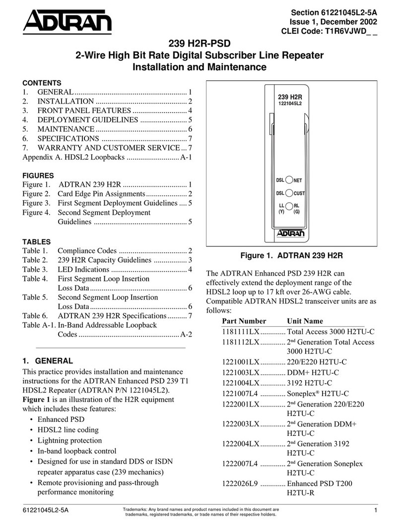
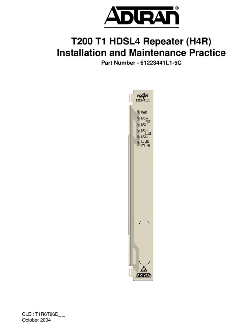
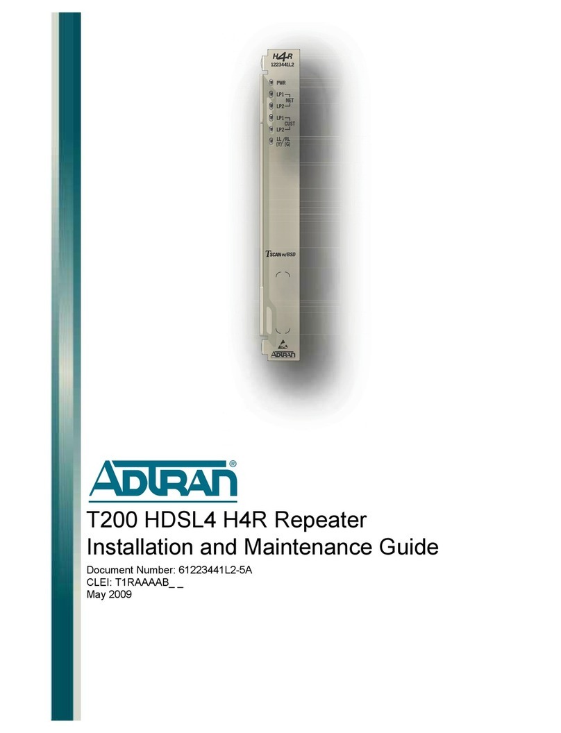
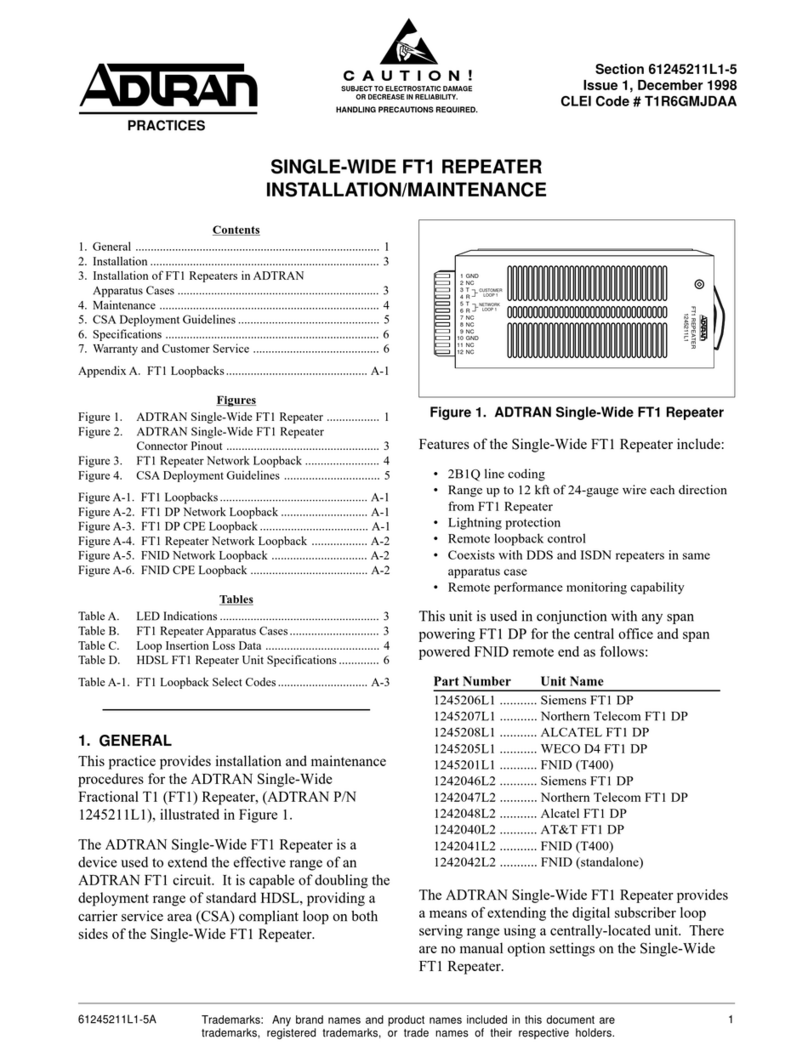
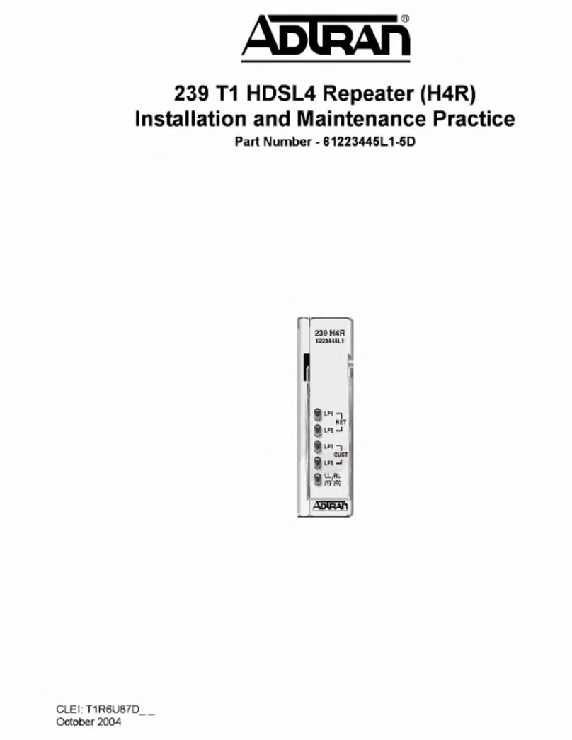
ADTRAN 239 H4R Instruction Manual

61221445L1-5A Section 61221445L1-5, Issue 1 1
Section 61221445L1-5A
Issue 1, June 2002
CLEI Code: T1R5YP3D_ _
239 H4R
HDSL4 Repeater
Installation and Maintenance
Trademarks: Any brand names and product names included in this document are
trademarks, registered trademarks, or trade names of their respective holders.
1. GENERAL
This practice provides installation and maintenance
(I/M) instructions for the ADTRAN 239 T HDSL4
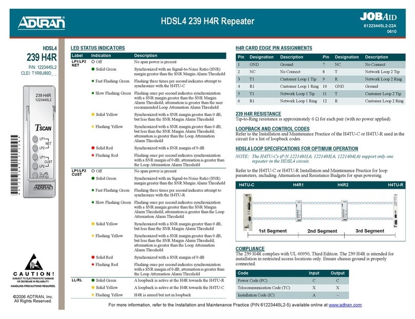
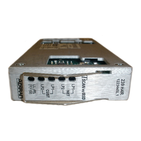
Repeater (H4R), P/N 22 445L . Figure 1 is an
illustration of the H4R. H4R equipment features
include:
• TC PAM line coding
• Lightning protection
• In-band loopback control
• Standard 239 form factor repeater apparatus case
design
• Remote provisioning and pass-through
performance monitoring
An ADTRAN span powered HDSL4 circuit consists
of an H4TU-C, up to two H4Rs and an H4TU-R. Due
to span power limits, the number of H4Rs permitted in
the circuit depends on the type of H4TU-C used. An
ADTRAN 239 H4R provides DS transport on all
revised resistance design (RRD) 26 AWG and/or 24
AWG loops. Two ADTRAN 239 H4R repeaters
extend the range of a loop up to 42.5 kft (24 AWG).
Repeater placement on single H4R loops depends only
on the attenuation properties of the loop segment.
Repeater placement for dual H4R loops requires both
segment attenuation and segment DC resistance
requirements be satisfied (refer to section 4, HDSL4
Deployment Guidelines).
Figure 1. ADTRAN 239 H4R
CONTENTS
. GENERAL ..............................................................
2. INSTALLATION ................................................... 2
3. FRONT PANEL FEATURES ................................ 5
4. HDSL4 DEPLOYMENT GUIDELINES ............... 6
5. MAINTENANCE ................................................. 0
6. SPECIFICATIONS ............................................... 0
7. WARRANTY AND CUSTOMER SERVICE ...... 0
FIGURES
Figure . ADTRAN 239 H4R .....................................
Figure 2. HDSL4 Circuit Segments .............................6
Figure 3. Resistance Budget Span Powering Two
Repeaters .....................................................8
Figure 4. Resistance Budget Span Powering Two
Repeaters (Example) .................................. 9
TABLES
Table . Card Edge Pin Assignment ......................... 2
Table 2. Compliance Codes ...................................... 3
Table 3. 239 H4R Capacity Guidelines for ADTRAN
Housings ..................................................... 3
Table 4. 239 H4R Capacity Guidelines for Other
Housings ..................................................... 4
Table 5. LED Indicators ........................................... 5
Table 6. Single Pair Cable DC Resistance
Value (Ω) .................................................... 7
Table 7. ADTRAN 239 H4R Specifications..........
239 H4R
1221445L1
LP1
NET
LP2
LP1
LP2
LL RL
(Y) (G)
/
CUST
261221445L1-5A
Section 61221445L1-5, Issue 1
The H4R is used in conjunction with any T .4 8
compliant span powering T HDSL4 transceiver unit
for the central office (H4TU-C) and HDSL4
transceiver unit for the remote end (H4TU-R).
Compatible ADTRAN HDSL4 transceiver units are as
follows:
Part Number Unit Name
1181411L1…..Total Access 3000 H4TU-C
1181411L4…..Total Access 3000 H4TU-C
1181411L5…..Total Access 3000 H4TU-C,
Protection Switching
1221401L1…..220/E220 H4TU-C
1221401L4…..220/E220 H4TU-C
1221401L6…..220/E220 H4TU-C
1221403L1…..DDM+ H4TU-C
1221403L4…..DDM+ H4TU-C
1221403L6…..DDM+ H4TU-C
1221404L1…..3192 H4TU-C
1221404L4…..3192 H4TU-C
1221404L6…..3192 H4TU-C
1221407L4…..Soneplex® H4TU-C
1221426L1…..T200 H4TU-R
1221426L6…..T200 H4TU-R
1221426L7…..T200 H4TU-R
1221424L1…..T200 H4TU-R, Local Power
1221424L6…..T200 H4TU-R, Local Power
1221424L7…..T200 H4TU-R, Local Power
There are no manual option settings on the H4R.
H4R operating power is derived from an H4TU-C,
independent of line impedance or wire gauge. The
operating power from the H4TU-C is also used to span
power the H4TU-R.
Revision History
This is the initial release of this document. Future
revisions to this document will be explained in this
subsection.
2. INSTALLATION
C A U T I O N
C A U T I O N
!
SUBJECT TO ELECTROSTATIC DAMAGE
OR DECREASE IN RELIABILITY.
HANDLING PRECAUTIONS REQUIRED.
Remove the ADTRAN 239 H4R from the carton and
visually ensure that damage has not occurred during
shipping or handling. If damage has occurred, file a
claim with the carrier, then contact ADTRAN. Refer
to the Warranty and Customer Service section of this
practice.
The ADTRAN 239 H4R is shipped in a separate carton
and must be installed in an environmental apparatus
case.
The ADTRAN 239 H4R is designed for deployment
using any 239-type repeater case. A retainer patch is
available for use with the 239 H4R for securing into the
ADTRAN apparatus cases.
When installing the ADTRAN 239 H4R, refer to the
Installation and Maintenance Practice for the housing
being used.
All connections are made through card edge
connectors. Table 1 gives the card edge pin
assignments.
CAUTION
The H4R dissipates a maximum of 5.4 watts.
Table 1. Card Edge Pin Assignment
niPnoitangiseDnoitpircseD
1DNGdnuorG
2CNtcennoCoN
31TpiT1pooLremotsuC
41RgniR1pooLremotsuC
51TpiT1pooLkrowteN
61RgniR1pooLkrowteN
7CNtcennoCoN
8T piT2pooLkrowteN
9R gniR2pooLkrowteN
01DNGdnuorG
11T piT2pooLremotsuC
21R gniR2pooLremotsuC

61221445L1-5A Section 61221445L1-5, Issue 1 3
NOTE
Ensure that the chassis ground is securely
connected to apparatus case. Ground pin
designations are defined in Table 1.
Compliance
Table 2 shows the Compliance Codes for the H4R.
The H4R complies with UL 60950, third edition. It is
intended for installation in restricted access locations
only and in equipment with a Type “B” or “E”
installation code.
Table 2. Compliance Codes
edoCtupnItuptuO
)CP(edoCrewoPCC
)CT(edoCnoitacinummoceleTXX
)CI(edoCnoitallatsnIA–
H4R Capacity Guidelines
The ADTRAN 239 H4R is designed for installation in
a prewired apparatus case, and the capacity guidelines
for deployment are defined in Table 3 and Table 4.
These housing capacity numbers are based upon
testing results.
Table 3. 239 H4R Capacity Guidelines for ADTRAN Housings
rebmuNtraPnoitpircseDedoCIELCstolSbutS
yticapaCR4H dednemmoceR
stnemngissAtolS lairetaM
evobA
dnuorG
woleB
dnuorG
evobA
dnuorG
woleB
dnuorG
1L7200511gnisuoH934/932AM1ABAOMDD4riA4 4 llAllAremyloP/sselniatS
2L7200511gnisuoH934/932AM1ABBOMDD4leG4 4 llAllAremyloP/sselniatS
1L7500511gnisuoHlasrevinUAR10ADOMDD4riA4 4 llAllAleetSsselniatS
2L7500511gnisuoHlasrevinUAR10ACOMDD4leG4 4 llAllAleetSsselniatS
1L8500511gnisuoHlasrevinUAR10EEOMDD8riA8 8 llAllAleetSsselniatS
2L8500511gnisuoHlasrevinUAR10EFOMDD8leG8 8 llAllAleetSsselniatS

461221445L1-5A
Section 61221445L1-5, Issue 1
Table 4. 239 H4R Capacity Guidelines for Other Housings
rerutcafunaMnoitpircseD traPs'rerutcafunaM
rebmuN stolSbutS
yticapaCR4HstnemngissAtolSdednemmoceR
lairetaM
evobA
dnuorG
woleB
dnuorG dnuorGevobAdnuorGwoleB
CDA IIrotaidaRTG610-GA-03-CXRH-XPS61riA6161llAllA leetSsselniatS
CDA IIrotaidaRTG610-GA-03-CXRH-XPS61leG6161llAllA leetSsselniatS
CDA rotaidaR1B-03-CXRH-XPS8riA8 8 llAllA leetSsselniatS
moceleTacriC A21-LSDH50006721riA2121llAllA lletSsselniatS
moceleTacriC B21-LSDH60006721leG2121llAllA lletSsselniatS
/tnecuL/sirrA
T&TA
letpeK
®
™kniLretnI
908
roXXX-3A908FR
XXX-3B908FR 21leG8 A/N 6,4,3,1
21,01,9,7 A/N remyloP
/tnecuL/sirrA
T&TA
letpeK
®
™kniLretnI
918/818
ro1A918FR
2A918FR
52riA21*61:1rebmahC
,7,4,1
41,11,8
:2rebmahC
91,71,51
52,32,02
:1rebmahC
,7,5,3,1
41,21,01,8
:2rebmahC
91,81,61,51
52,42,22,02
remyloP
/tnecuL/sirrA
T&TA
letpeK
®
™kniLretnI
918/818
ro1B918FR
2B918FR
52riA21*61:1rebmahC
,7,4,1
41,11,8
:2rebmahC
91,71,51
52,32,02
:1rebmahC
,7,5,3,1
41,21,01,8
:2rebmahC
91,81,61,51
52,42,22,02
remyloP
/tnecuL/sirrA
T&TA
letpeK
®
™kniLretnI
ylimaF028
roXA028FR
XB028FR 8ot2riAlluFlluFllAllA remyloP
/tnecuL/sirrA
T&TA
etpeK
®
™kniLretnI
ylimaF028
roXA028FR
XB028FR 8ot2leGlluFlluFllAllA remyloP
.)Cº1.64(Fº511deecxetondluohsgnisuohehtotlellarapdnayawatf1derusaemerutarepmetriatneibmaeht,esutols61roF*

61221445L1-5A Section 61221445L1-5, Issue 1 5
3. FRONT PANEL FEATURES
The ADTRAN H4R front panel has five LEDs
indicating different states of the HDSL4 circuit.
Table 5 explains the meaning of the different LED
indicators.
Table 5. LED Indicators
Five Tricolored Front Panel LEDs Indicate these H4R States.
239 H4R
1221445L1
LP1
NET
LP2
LP1
LP2
LL RL
(Y) (G)
/
CUST
DELnoitacidnInoitpircseD
2PL/1PL
TEN
ffO
neerGdiloS
neerGgniknilBtsaF
neerGgniknilBwolS
wolleYdiloS
wolleYgniknilBwolS
deRdiloS
deRgniknilBwolS
tneserpsirewopnapsoN
RNSdenifedresuehtnahtretaergnigramRNSnahtiwdezinorhcnyS
dlohserhTmralAnigraM
C-UT4HehthtiwezinorhcnysotgnitpmettA)dnocesrepsemit3gniknilB(
nahtretaergnigramRNSahtiwdezinorhcnyS)dnocesrepemit1gniknilB(
sinoitaunettaeslupehtdnadlohserhTmralAnigraMRNSdenifedresueht
dlohserhTmralAnoitaunettApooLdenifedresuehtnahtretaerg
resuehtnahtsseltubBd0nahtretaergnigramRNSahtiwdezinorhcnyS
dlohserhTmralAnigraMRNSdenifed
resuehtnahtsseltubBd0nahtretaergnigramRNSahtiwdezinorhcnyS
retaergsinoitaunettaeslupehtdnadlohserhTmralAnigraMRNSdenifed
dlohserhTmralAnoitaunettApooLdenifedresuehtnaht
Bd0fonigramRNSahtiwdezinorhcnyS
dnaBd0fonigramRNSahtiwdezinorhcnyS)dnocesrepemit1gniknilB(
noitaunettApooLdenifedresuehtnahtretaergsinoitaunettaeslupeht
dlohserhTmralA
2PL/1PL
TSUC
ffO
neerGdiloS
neerGgniknilBtsaF
neerGgniknilBwolS
wolleYdiloS
wolleYgniknilBwolS
deRdiloS
deRgniknilBwolS
tneserpsirewopnapsoN
RNSdenifedresuehtnahtretaergnigramRNSahtiwdezinorhcnyS
dlohserhTmralAnigraM
R-UT4HehthtiwezinorhcnysotgnitpmettA)dnocesrepsemit3gniknilB(
nahtretaergnigramRNSahtiwdezinorhcnyS)dnocesrepemit1gniknilB(
sinoitaunettaeslupehtdnadlohserhTmralAnigraMRNSdenifedresueht
dlohserhTmralAnoitaunettApooLdenifedresuehtnahtretaerg
resuehtnahtsseltubBd0nahtretaergnigramRNSahtiwdezinorhcnyS
dlohserhTmralAnigraMRNSdenifed
resuehtnahtsseltubBd0nahtretaergnigramRNSahtiwdezinorhcnyS
retaergsinoitaunettaeslupehtdnadlohserhTmralAnigraMRNSdenifed
dlohserhTmralAnoitaunettApooLdenifedresuehtnaht
Bd0fonigramRNSahtiwdezinorhcnyS
dnaBd0fonigramRNSahtiwdezinorhcnyS)dnocesrepemit1gniknilB(
noitaunettApooLdenifedresuehtnahtretaergsinoitaunettaeslupeht
dlohserhTmralA
LR/LLwolleYdiloS
wolleYgniknilBwolS
neerGdiloS
evitcasiC-UT4HehtdrawotR4HehttakcabpoolasetacidnI
kcabpoolnitontubdemrasiR4H
evitcasiR-UT4HehtdrawotR4HehttakcabpoolasetacidnI

661221445L1-5A
Section 61221445L1-5, Issue 1
4. HDSL4 DEPLOYMENT GUIDELINES
NOTE
The H4TU-Cs (P/Ns: 1221401L6, 1221403L6,
and 1221404L6) support only one H4R in the
HDSL4 circuit.
The different segments of an HDSL4 circuit are
defined in Figure 2.
1st Segment
H4TU-C 1st H4R 2nd H4R H4TU-R
2nd Segment 3rd Segment
Figure 2. HDSL4 Circuit Segments
According to the number of H4Rs in the HDSL4
circuit, the following service ranges apply:
• HDSL4 circuit containing no H4Rs will reach up
to 16 kft on the local loop (24 AWG)
• HDSL4 circuit containing one H4R will reach up
to 16 kft on the first segment and 15 kft on the
second segment (24 AWG)
• HDSL4 circuit containing two H4Rs will reach to
13.5 kft on the first segment, 14 kft on the second
segment, and 15 kft on the third segment
(24 AWG) *
*This is one example of a circuit with 2 H4 s.
Other loop length configurations are possible in
compliance with loop resistance restraints.
NOTE
Refer to the H4TU-C or H4TU-R Installation
and Maintenance Practice, HDSL4 Deployment
Guidelines section, for other loop parameters
including Insertion Loss and Pulse Attenuation.
The ADTRAN HDSL4 system provides DS -based
services over loops designed to comply with the
guidelines given below.
1. All loops are nonloaded only.
2. Any single bridged tap is limited to 2 kft.
3. Total bridged tap length is limited to 2.5 kft.
NOTE
Refer to the Detailed Status Screen (Main Menu
selection “3,” Span Status selection “1”) for the
current loop SNR Margin, Insertion Loss, and
Pulse Attenuation status.

61221445L1-5A Section 61221445L1-5, Issue 1 7
Each of the three segments associated with span
powering two H4Rs and an H4TU-R must satisfy the
recommended insertion loss, loop attenuation
requirements in addition to the DC resistance budgets.
In general, 22 and 9 AWG segments will be
restricted by their loop attenuation while the DC
resistance will restrict the segment reach for 26 and 24
AWG. When designing a dual H4R loop, the first
segment should have lower DC resistance than the
second segment. Single H4R spans do not require any
restriction due to DC resistance.
The segment resistance (Ω segment) is determined using
the equation provided below.
Ωsegment = L26 * Ω26 + L24 * Ω24 + L22 * Ω22 + L 9 * Ω9
where : L# is the length of # AWG cable (kft,
excluding bridge taps), Ω# is the D.C.
Resistance of # AWG cable
Table 6 lists single pair cable DC resistance values to
be used in the equation above.
Table 6. Single Pair Cable DC Resistance Value (ΩΩ
ΩΩ
Ω)
)tfk/smho(ecnatsiseR
GWA)F(geD07*)F(geD09)F(geD021**)F(geD041
91
22
42
62
564.61
600.33
894.25
574.38
381.71
644.43
987.45
711.78
162.81
606.63
522.85
185.29
979.81
640.83
615.06
322.69
*atadF°021dnaF°07neewtebdetalopretnI
atadF°021dnaF°07morfdetalopartxE**

861221445L1-5A
Section 61221445L1-5, Issue 1
Once the resistance of each segment is confirmed,
refer to Figure 3 to decide if the H4TU-C is capable
of span powering two H4Rs and one H4TU-R.
Follow these steps to utilize the graph shown in Figure
3:
1. Find the line on the graph which represents the
known third segment resistance. These are the
lines running diagonally across the graph labeled
300 - 1100 ohms. This line represents the upper
limit for 2 H4Rs plus H4TU-R span powering.
2. Find the first segment resistance on the vertical
axis.
3. Find the second segment resistance on the
horizontal axis.
4. Find the instance where the two points from steps
2 and 3 meet on the graph.
5. The point found in step 4 must be below the
upper limit line defined by the third segment
measurement (step 1). If the instance where these
two points is above this line, the H4TU-C cannot
span power two H4Rs and the H4TU-R.
Note that these measurements represent only one of
the two HDSL4 pairs.
Figure 3. Resistance Budget Span Powering Two Repeaters
3
0
0
o
h
m
s
5
0
0
o
h
m
s
7
0
0
o
h
m
s
9
0
0
o
h
m
s
1
1
0
0
o
h
m
s
HDSL4 Single Pair Resistance for Span Powering Two Repeaters and an H4TU-R
Resistance Budget
Second Segment Resistance (ohms)
First Segment Resistance (ohms)
1200
1100
1000
900
800
700
600
500
400
400 500 600 700 800 900 1000 1100
WITHIN LIMITS
OUTSIDE LIMITS
Third Segment Resistance

61221445L1-5A Section 61221445L1-5, Issue 1 9
An example problem is illustrated in Figure 4. For
this example, begin with three known measurements:
700 ohms first segment resistance, 800 ohms second
segment resistance, and 900 ohms third segment
resistance. See Figure 4 and the following steps to
solve the example problem:
1. Find the 900 ohms third segment resistance line
on the graph. This line is depicted in bold in
Figure 4. This line is the upper span power limit.
2. Find the 700 ohms first segment resistance point
on the vertical axis.
3. Find the 800 ohms second segment resistance
point on the horizontal axis.
Figure 4. Resistance Budget Span Powering Two Repeaters (Example)
9
0
0
o
h
m
s
HDSL4 Single Pair Resistance for Span Powering Two Repeaters and an H4TU-R
Resistance Budget
Second Segment Resistance (ohms)
First Segment Resistance (ohms)
1200
1100
1000
900
800
700
600
500
400
400 500 600 700 800 900 1000 1100
WITHIN LIMITS
OUTSIDE LIMITS
3
0
0
o
h
m
s
5
0
0
o
h
m
s
7
0
0
o
h
m
s
1
1
0
0
o
h
m
s
4. Find the instance on the graph where the points
from steps 2 and 3 meet.
5. Is this point below the bold line defined in
step 1? Yes. Therefore, a circuit with these
parameters is capable of span powering two
H4Rs and one H4TU-R.

10 61221445L1-5A
Section 61221445L1-5, Issue 1
5. MAINTENANCE
The ADTRAN 239 H4R requires no routine
maintenance. In case of equipment malfunction,
perform an in-band loopback from the central office
(CO). If a malfunction is confirmed, replace the unit.
The ADTRAN 239 H4R has looping capability through
the channel allowing digital loopback in fault isolation.
The looping is accomplished remotely.
Performance monitoring, diagnostics, and loopbacks
are also available from the craft interface at the
H4TU-C and H4TU-R.
The type of loopbacks that the H4R supports will
depend on what type of transceiver units are used in
the circuit. Refer to the Installation and Maintenance
Practice of the specific H4TU-C or H4TU-C for a list
of loopback codes.
When testing indicates a faulty circuit pack, refer to
the housing Installation and Maintenance Practice for
the entry and pressurization control, then replace the
faulty circuit pack.
ADTRAN does not recommend field repair of this
unit. Repair services may be obtained by returning
the defective unit to the ADTRAN Customer and
Product Support (CAPS) Department.
6. SPECIFICATIONS
Specifications for the ADTRAN 239 H4R are detailed
in Table 7.
7. WARRANTY AND CUSTOMER SERVICE
ADTRAN will replace or repair this product within
ten ( 0) years from the date of shipment if it does not
meet its published specifications or fails while in
service. Refer to ADTRAN U.S. and Canada Carrier
Networks Equipment Warranty, Document
60000087- 0.
Contact Customer and Product Services (CAPS) prior
to returning equipment to ADTRAN.
For service, CAPS requests, or further information,
contact one of the following numbers:
ADTRAN Sales
Pricing/Availability
(800) 827-0807
ADTRAN Technical Support
Pre-sales Applications/Post-sales Technical
Assistance
(800) 726-8663
Standard hours: Monday-Friday, 7 a.m. - 7 p.m. CST
Emergency hours: 7 days/week, 24 hours/day
ADTRAN Repair/CAPS
Return for Repair/Upgrade
(256) 963-8722
Repair and Return Address
ADTRAN, Inc.
CAPS Department
901 Explorer Boulevard
Huntsville, Alabama 35806-2807

61221445L1-5A Section 61221445L1-5, Issue 1 11
Table 7. ADTRAN 239 H4R Specifications
ecafretnIpooL
epyTnoitaludoM
edoM
sriaPforebmuN
etaReniL
etaRduaB
egnaRecivreS
ssoLpooL
spaTdegdirB
ecnamrofreP
leveL)ataD(rewoPtimsnarTC-UT4H
leveL)noitavitcA(rewoPtimsnarTC-UT4H
ecnedepmItupnI
ecnatsiseRpooLmumixaM
ssoLnruteR
MAPCT61
gnilecnacohcedeppalrevoyllaitraP,xelpuDlluF
owT
spbM255.1
duabk333.162
tnemgeSdrihTtfK51,tnemgeSdnoceStfK41,tnemgeStsriFtfK5.31
.elbissoperasnoitanibmochtgnelpoolrehtotahtetoN;)GWA42(
ecitcarPecnanetniaMdnanoitallatsnIR-UT4HroC-UT4HotrefeR
noitceS(
)senilediuGtnemyolpeD4LSDH
tf0052<spaTlatoT,tf0002<spaTelgniS
)2eussi,dradnatS2LSDH(0002-814.1ThtiwtnailpmoC
)zHk004ot0(mBd5.0±1.41
)zHk703ot0(mBd5.0±1.41
mho531
ecitcarPecnanetniaMdnanoitallatsnIR-UT4HroC-UT4HotrefeR
noitceS(
)senilediuGtnemyolpeD4LSDH
)zHk002otzHk05(Bd21
rewoP
rewoPtupnI mumixam,sttaw4.5)C-UT4HybderewopnapS(
kcolC
secruoSkcolC
ycaruccAkcolClanretnI
deFxuM,)gniffutstibemarf4LSDHhtiw(devireD1-XSD
stnemeriuqeRgnimiT101.1TsteeM,)4mutartSsdeecxE(mpp52±
stseT
scitsongaiD roC-UT4Hmorfrosedocdnab-ni4LSDHhtiwdetaitiniskcabpooL
.ecafretnitfarcR-UT4H
lacisyhP
thgieW.bl1<
tnemnorivnE
)dradnatS(erutarepmeTgnitarepO
erutarepmeTegarotS
suisleCseergeD07+otseergeD04-
suisleCseergeD58+otseergeD04-
ecnailpmoC
05906LU
3leveLSBEN
AssalC,51traPRFC74CCF
rebmuNtraP
R4H9321L5441221

12 61221445L1-5A
Section 61221445L1-5, Issue 1
Other manuals for 239 H4R
2
This manual suits for next models
1
Table of contents
Other ADTRAN Repeater manuals

ADTRAN
ADTRAN HDSL4 T200 H4TU-R Product manual

ADTRAN
ADTRAN 239 T1 Instruction Manual

ADTRAN
ADTRAN 1223445L2 User manual

ADTRAN
ADTRAN 239 H2R-PSD Instruction Manual

ADTRAN
ADTRAN 239 H4R Instruction Manual

ADTRAN
ADTRAN D4-U-RPM Maintenance and service guide

ADTRAN
ADTRAN T200 T1 HDSL4 Instruction Manual

ADTRAN
ADTRAN NetVanta FT1 Maintenance and service guide