GMI D5016SS User manual

D5016 - SIL 3 4-wire HART® Transmitter Current Repeater G.M. International ISM0553-0
SIL 3 2-wire Active HART®Tx Current Repeater
DIN-Rail and Termination Board,
Models D5016SS, D5016SK, D5016DS, D5016DK
D5016SS - D5016SK - D5016DS - D5016DK
INSTRUCTION MANUAL

D5016 - SIL 3 4-wire HART® Transmitter Current Repeater G.M. International ISM0553-0
2
General Description:
The Current Repeater D5016 module is a high integrity analog input interface suitable for applications requiring SIL 3 level (according to IEC 61508:2010 Ed.2) in safety related
systems for high risk industries.
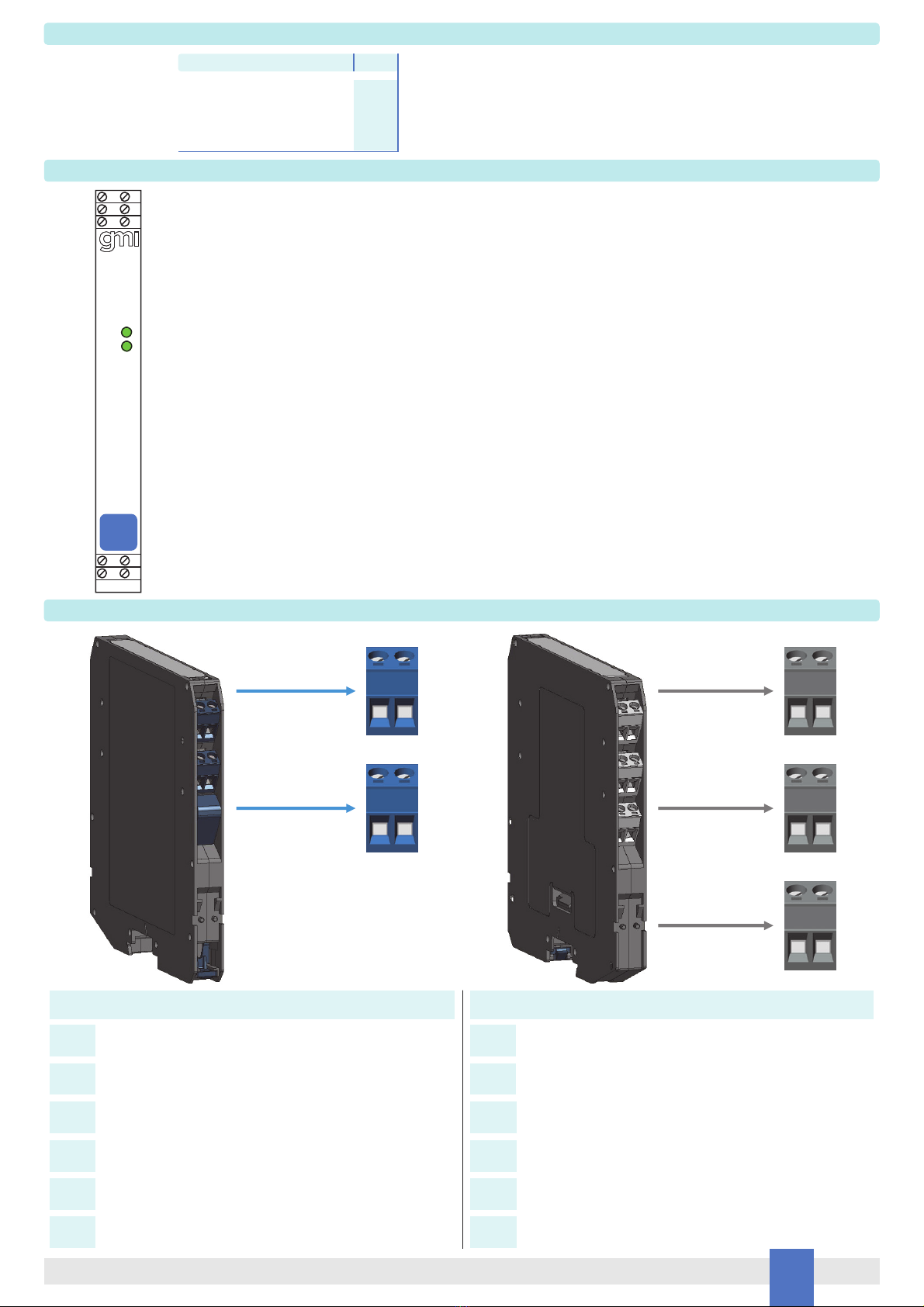
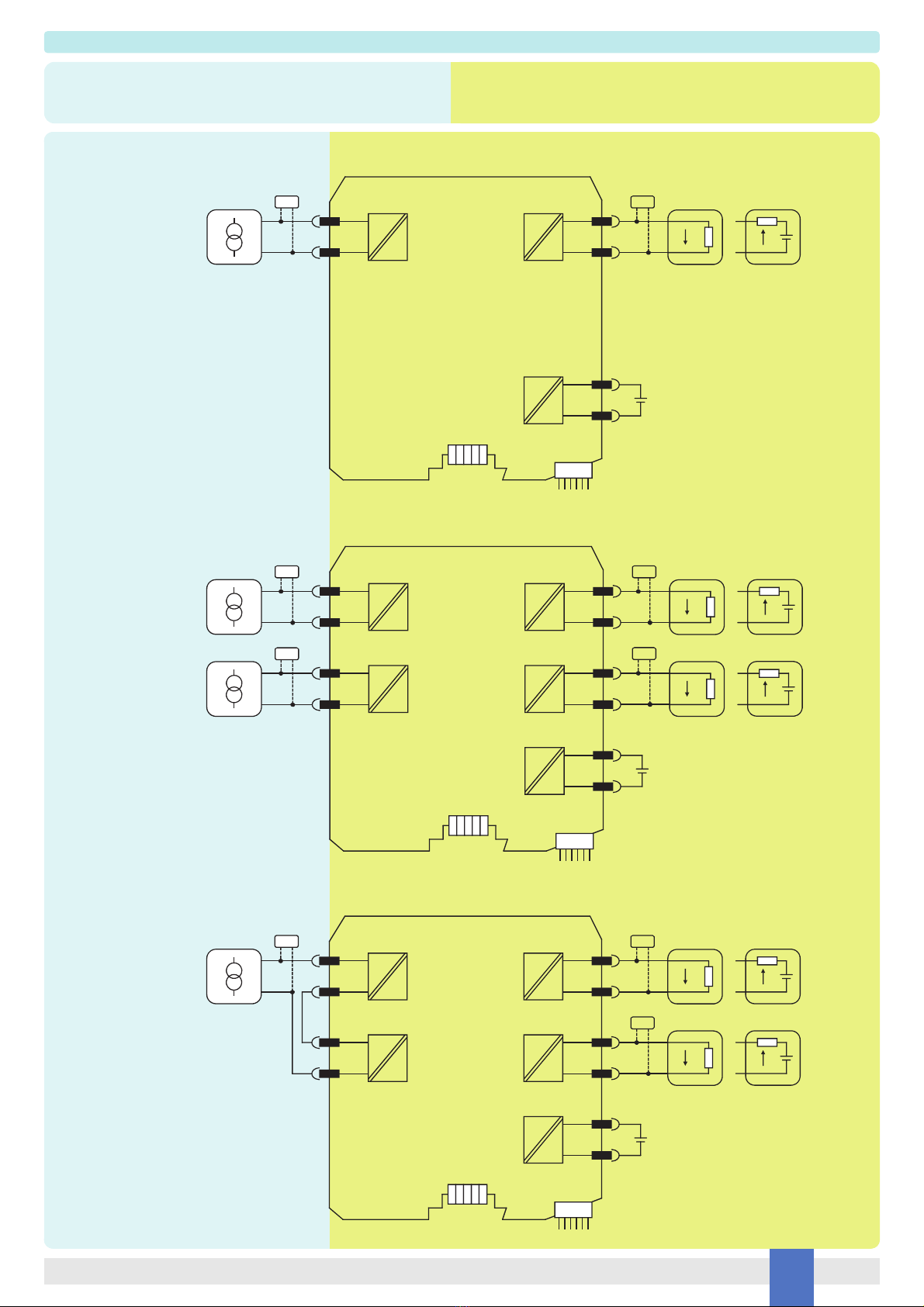
It repeats a 2-wire active 4-20 mA current signal input floating circuit to drive a Safe Area load.
The module allows bi-directional communication signals, for HART® devices.
Mounting on standard DIN-Rail, with or without Power Bus, or on customized Termination Boards, in Safe Area or in Zone 2.
D5016SS: Single channel, source output. D5016SK: Single channel, sink output. D5016DS: Double channel, source output. D5016DK: Double channel, sink output.
Technical Data
Characteristics
Supply:
24 Vdc nom (18 to 30 Vdc) reverse polarity protected.
Current consumption: 32 mA (D5016SS), 20 mA (D5016SK), 60 mA (D5016DS), 30 mA (D5016DK) @ 24 Vdc with 20 mA output, typical.
Power dissipation: 0.80 W (D5016SS), 1.00 W (D5016SK), 1.50 W (D5016DS), 1.74 W (D5016DK) @ 24 Vdc with 20 mA output on 250 Ωload and 24 Vdc output supply for sink
models, typical.
Isolation (Test Voltage):
I.S. In/Out 2.5 kV; I.S. In/Supply 2.5 kV; I.S. In/I.S. In 500 V; Out/Supply 500 V; Out/Out 500 V.
Input:
4 to 20 mA (separately powered input, voltage drop ≤7 V), reading range 0 to 22 mA.
HART Impedance: 225 Ω, typical.
Output:
4 to 20 mA.
Sink out voltage range: 2 to 30 V.
Load range: 0 to 500 Ω, with conventional Tx input 250 Ωnom (160 to 500 Ω), with smart Tx input.
Current limitation: 24 mA (up to 450 Ωload) ≤max current ≤26 mA.
Response time: 20 ms (10 to 90 % step change).
Performance:
Ref. Conditions: 24 V supply, 250 Ωload, 23 ± 1 °C ambient temperature.
Calibration accuracy: ≤± 20 μA.
Linearity accuracy: ≤± 20 μA.
Supply voltage influence: ≤± 4 μA for a min to max supply change.
Load influence: ≤± 4 μA for a 0 to 100 % load resistance change.
Temperature influence: ≤± 2 μA/°C.
Compatibility:
CE mark compliant, conforms to Directives:
2014/34/EU ATEX, 2014/30/EU EMC, 2014/35/EU LVD, 2011/65/EU RoHS.
Environmental conditions:
Operating: temperature limits – 40 to + 70 °C, relative humidity 95 %, up to 55 °C.
Max altitude: 2000 m a.s.l.
Storage: temperature limits – 45 to + 80 °C.
Safety Description:
ATEX: II 3(1)G Ex ec [ia Ga] IIC T4 Gc, II (1) D [Ex ia Da] IIIC, I (M1) [Ex ia Ma] I
IECEx: Ex ec [ia Ga] IIC T4 Gc, [Ex ia Da] IIIC, [Ex ia Ma] I
UL: NI / I / 2 / ABCD / T4, AIS / I, II, III / 1 / ABCDEFG, AEx ec [ia Ga] IIC T4 Gc; C-UL: NI / I / 2 / ABCD / T4, AIS / I, II, III / 1 / ABCDEFG, Ex ec [ia Ga] IIC T4 Gc X
Uo/Voc = 8.8 V, Io/Isc = 0 mA, Po/Po = 0 mW at terminals 7-8 and 9-10,
Ui/Vmax = 30 V, Ii/Imax = 100 mA, Ci = 1.1 nF, Li = 0 nH at terminals 7-8 and 9-10,
Um = 250 Vrms or Vdc, -40 °C ≤Ta ≤70 °C.
Approvals:
UL 22 ATEX 2892X conforms to EN60079-0, EN60079-11, EN60079-7.
IECEx ULD 22.0034X conforms to IEC60079-0, IEC60079-11, IEC60079-7.
UL & C-UL E222308 conforms to UL61010-1, UL913, UL 121201, UL 60079-0, UL60079-11, UL60079-7 for UL
and CAN/CSA C22.2 No. 61010-1-12, CSA C22.2 No. 213, CAN/CSA C22.2 No. 60079-0, CAN/CSA C22.2 No. 60079-11, CAN/CSA No. 60079-7 for C-UL.
SIL 3 conforms to IEC61508:2010 Ed. 2.
Mounting:
EN/IEC60715 TH 35 DIN-Rail, with or without Power Bus or on customized Termination Board.
Weight: about 135 g (D5016DS and D5016DK), 115 g (D5016SS and D5016SK).
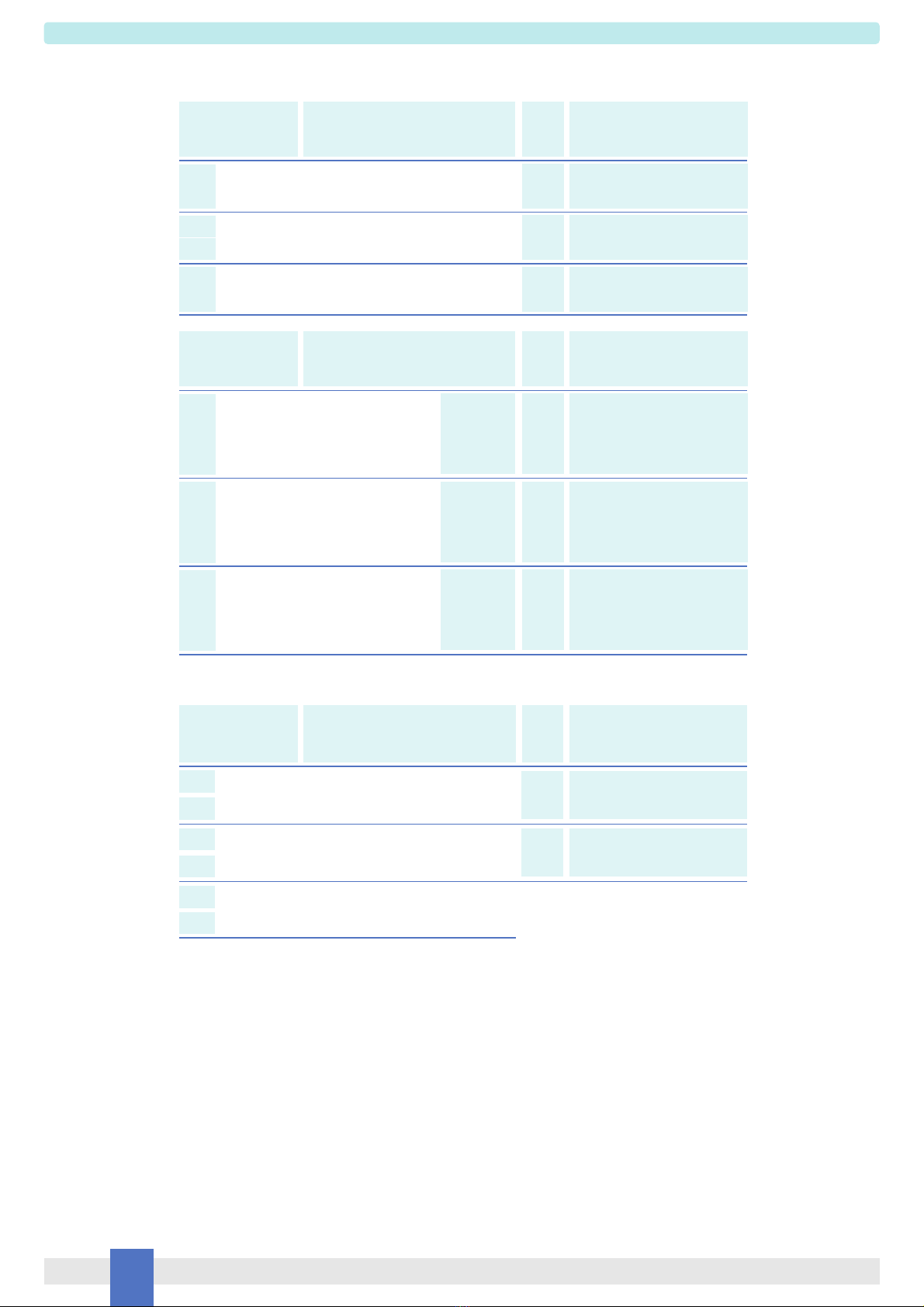
Connection: by polarized plug-in disconnect screw terminal blocks to accommodate terminations up to 2.5 mm2(13 AWG).
Location: installation in Safe Area or Zone 2, Group IIC T4.
Protection class: IP 20.
Dimensions: Width 12.5 mm, Depth 123 mm, Height 120 mm.

D5016 - SIL 3 4-wire HART® Transmitter Current RepeaterG.M. International ISM0553-0 3
Ordering Information
Front Panel and Features
Input from Zone 0 / Division 1.
Installation in Zone 2 / Division 2.
4-20 mA Input Signal Active.
4-20 mA Output Signal Source-Sink.
HART® compatible.
Input and Output short circuit proof.
High Accuracy.
High Density, two channels per unit.
Three port isolation, Input/Output/Supply.
EMC Compatibility to EN61000-6-2, EN61000-6-4, EN61326-1, EN61326-3-1 for safety systems.
ATEX, IECEx, UL & C-UL Certification.
Simplified installation using standard DIN-Rail and plug-in terminal blocks, with or without Power Bus, or customized Termination
Boards.
250 Vrms (Um) max. voltage allowed to the instruments associated with the barrier.
+ Input Ch 1 for External Powered Transmitters
Terminal block connections
HAZARDOUS AREA SAFE AREA
- Input Ch 1 for External Powered Transmitters
+ Input Ch 2 for External Powered Transmitters
- Input Ch 2 for External Powered Transmitters
-
-
7
8
9
10
11
12
+ Output Ch 1
1
- Output Ch 1
2
+ Output Ch 2
3
- Output Ch 2
4
+ Power Supply 24 Vdc
5
- Power Supply 24 Vdc
6
Model: D5016
1 channel source output SS
1 channel sink output SK
Power Bus and DIN-Rail accessories:
Bus Connector JDFT049 Bus Mounting Kit OPT5096
2 channels source outputs DS
2 channels sink outputs DK
D5016
7 8
1 2
5 6
SIL 3
PWR
3 4
9 10
1
PWR 2
7 8
9 10
12
34
56

D5016 - SIL 3 4-wire HART® Transmitter Current Repeater G.M. International ISM0553-0
4
Parameters Table
When used with separate powered intrinsically safe devices, check that maximum allowable voltage, current (Ui/Vmax, Ii/Imax) of the D5016 Associated Apparatus are not exceeded by
the safety parameters (Uo/Voc, Io/Isc) of the Intrinsically Safe device, indicated in the table below:
For installations in which both the Ci and Li of the Intrinsically Safe apparatus exceed 1% of the Co and Lo parameters of the Associated Apparatus (excluding the cable),
then 50% of Co and Lo parameters are applicable and shall not be exceeded (50% of the Co and Lo become the limits which must include the cable such that Ci device + C cable ≤
50 % of Co and Li device + L cable ≤50 % of Lo). The reduced capacitance of the external circuit (including cable) shall not be greater than 1 μF for Groups I, IIA, IIB and 600 nF for
Group IIC. If the cable parameters are unknown, the following value may be used: Capacitance 200 pF per meter (60 pF per foot), Inductance 1 µH per meter (0.20 µH per foot).
Must
be
Hazardous Area/
Hazardous Locations
Device Parameters
D5016 Associated
Apparatus Parameters
Ui / Vmax = 30 V Uo / Voc
D5016 Terminals
Ch1
Ch2
7 - 8
9 - 10
≥
Ci = 1.1 nF, Li= 0 nH
Ch1
Ch2
7 - 8
9 - 10
Must
be
Hazardous Area/
Hazardous Locations
Device Parameters
D5016 Associated
Apparatus Parameters
Ui / Vmax
In the system safety analysis, always check the Hazardous Area/Hazardous Locations devices to conform with the related system documentation, if the device is Intrinsically Safe check
its suitability for the Hazardous Area/Hazardous Locations and group encountered and that its maximum allowable voltage, current, power (Ui/Vmax, Ii/Imax, Pi/Pi) are not exceeded
by the safety parameters (Uo/Voc, Io/Isc, Po/Po) of the D5016 series Associated Apparatus connected to it. See parameters indicated in the table below:
D5016 Terminals
Uo / Voc = 8.8 V
Ch1
Ch2
7 - 8
9 - 10 ≤
Ii/ Imax
Io / Isc = 0 mA
Ch1
Ch2
7 - 8
9 - 10 ≤
Pi / Pi
Po / Po = 0 mW
Ch1
Ch2
7 - 8
9 - 10 ≤
Must
be
Hazardous Area/
Hazardous Locations
Device Parameters
D5016 Associated
Apparatus Parameters
Ci / Ci device + C cable
D5016 Terminals
Ch1
Ch2
7 - 8
9 - 10
≥
IIC (A,B)
Co / Ca = 5.4 µF
IIB (C)
Co / Ca = 45.9 µF
IIA (D)
Co / Ca = 729.9 µF
I
Co / Ca = 999.9 µF
IIIC (E,F,G)
Co / Ca = 45.9 µF
Li / Li device + L cable
Ch1
Ch2
7 - 8
9 - 10
≥
IIC (A,B)
Lo / La = 1000 mH
IIB (C)
Lo / La = 1000 mH
IIA (D)
Lo / La = 1000 mH
I
Lo / La = 1000 mH
IIIC (E,F,G)
Lo / La = 1000 mH
Li / Ri device and
L cable / R cable
Ch1
Ch2
7 - 8
9 - 10
≥
IIC (A,B)
Lo / Ro = N/A
IIB (C)
Lo / Ro = N/A
IIA (D)
Lo / Ro = N/A
I
Lo / Ro = N/A
IIIC (E,F,G)
Lo / Ro = N/A
Ii / Imax = 100 mA Io / Isc
Ch1
Ch2
7 - 8
9 - 10
≥

D5016 - SIL 3 4-wire HART® Transmitter Current RepeaterG.M. International ISM0553-0 5
Function Diagram
HAZARDOUS AREA ZONE 0 (ZONE 20) GROUP IIC,
HAZARDOUS LOCATIONS CLASS I, DIVISION 1, GROUPS A, B, C, D,
CLASS II, DIVISION 1, GROUPS E, F, G, CLASS III, DIVISION 1,
CLASS I, ZONE 0, GROUP IIC
SAFE AREA, ZONE 2 GROUP IIC T4,
NON HAZARDOUS LOCATIONS, CLASS I, DIVISION 2,
GROUPS A, B, C, D T-Code T4, CLASS I, ZONE 2, GROUP IIC T4
7
8
1
2
In
+
5
6
Supply
Out
HHT
D5016S*
TB
Connector
BUS Connector
HHT Sink I
+
-
mA +
mA
Source I
+
-
+
-
External
Powered Tx
D5016SS D5016SK
7
8
1
2
In 1
+
5
6
Supply
Out 1
HHT
D5016D*
TB
Connector
BUS Connector
HHT Sink I
+
-
mA +
mA
Source I
+
-
+
-
External
Powered Tx
9
10
3
4
In 2 Out 2
HHT Sink I
+
-
mA +
mA
Source I
+
-
HHT
+
-
External
Powered Tx
D5016DS D5016DK
7
8
1
2
In
+
5
6
Supply
Out 1
D5016D* Duplicator
TB
Connector
BUS Connector
HHT Sink I
+
-
mA +
mA
Source I
+
-
External
Powered Tx
9
10
3
4
Out 2
HHT Sink I
+
-
mA +
mA
Source I
+
-
D5016DS D5016DK
+
-
HHT

D5016 - SIL 3 4-wire HART® Transmitter Current Repeater G.M. International ISM0553-0
6
D5016 series are isolated Intrinsically Safe Associated Apparatus installed into standard EN/IEC60715 TH 35 DIN-Rail located in Safe Area or Zone 2, Group IIC, Temperature T4 or
Class I, Division 2, Group A, B, C, D, T4 Hazardous Area within the specified operating temperature limits Tamb -40 to +70 °C, and connected to equipment with a maximum limit for
power supply Um of 250 Vrms or Vdc.
Not to be connected to control equipment that uses or generates more than 250 Vrms or Vdc with respect to earth ground.
D5016 series must be installed, operated and maintained only by qualified personnel, in accordance to the relevant national/international installation standards (e.g. EN/IEC60079-14
Electrical apparatus for explosive gas atmospheres - Part 14: Electrical installations in hazardous areas (other than mines)), following the established installation rules, particular care
shall be given to segregation and clear identification of I.S. conductors from non I.S. ones.
De-energize power source (turn off power supply voltage) before plug or unplug the terminal blocks when installed in Hazardous Area or unless area is known to be nonhazardous.
Warning: substitution of components may impair Intrinsic Safety and suitability for Zone 2.
Explosion Hazard: to prevent ignition of flammable atmospheres, disconnect power before servicing or unless area is known to be nonhazardous.
Failure to properly installation or use of the equipment may risk to damage the unit or severe personal injury.
The unit cannot be repaired by the end user and must be returned to the manufacturer or his authorized representative. Any unauthorized modification must be avoided.
Warning
Operation
D5016 repeats an externally powered 4-wire 4-20 mA current signal input floating circuit to drive a Safe Area load.
The module allows bi-directional communication signals, for HART® devices. A “POWER ON” green led for each channel lits when input power is present.
Installation
D5016 series are Repeater power supply HART® compatible housed in a plastic enclosure suitable for installation on EN/IEC60715 TH 35 DIN-Rail, with or without Power Bus or on
customized Termination Board. D5016 series can be mounted with any orientation over the entire ambient temperature range.
Electrical connections are accommodated by polarized plug-in removable screw terminal blocks which can be plugged in/out into a powered unit without suffering or causing any damage
(for Zone 2 installations check the area to be nonhazardous before servicing). Connect only one individual conductor per each clamping point, use conductors from 0.2 mm2
(24 AWG) up to 2.5 mm² (13 AWG) and a torque value of 0.5-0.6 Nm. For USA and Canada installations, use only cables that are suitable for a temperature of at least 75°C.The wiring
cables have to be proportionate in base to the current and the length of the cable.
On the section “Function Diagram” and enclosure side a block diagram identifies all connections.
Intrinsically Safe conductors must be identified and segregated from non I.S. and wired in accordance to the relevant national/international installation standards (e.g. EN/IEC60079-14
Electrical apparatus for explosive gas atmospheres -Part 14: Electrical installations in hazardous areas (other than mines)), make sure that conductors are well isolated from each other
and do not produce any unintentional connection. Isolation in accordance with EN/IEC 60079-11 clause 6.3.13 is provided between non-intrinsically safe circuits and intrinsically safe
circuits.
The enclosure provides, according to EN60529, an IP20 minimum degree of protection (or similar to NEMA Standard 250 type 1). The equipment shall only be used in an area of at least
pollution degree 2, as defined in IEC 60664-1. When installed in EU Zone 2, the unit shall be installed in an enclosure that provides a minimum ingress protection of IP54 in accordance
with IEC 60079-0. When installed in a Class I, Zone 2 Hazardous Location, the unit shall be mounted in a supplemental AEx or Ex enclosure that provides a degree of protection not less
than IP54 in accordance with UL/CSA 60079-0. When installed in a Class I, Division 2 Hazardous Location, the unit shall be mounted in a supplemental enclosure that provides a degree
of protection not less than IP54. The enclosure must have a door or cover accessible only by the use of a tool. The end user is responsible to ensure that the operating temperature of
the module is not exceeded in the end use application.
Units must be protected against dirt, dust, extreme mechanical (e.g. vibration, impact and shock) and thermal stress, and casual contacts. If enclosure needs to be cleaned use only a
cloth lightly moistened by a mixture of detergent in water.
Electrostatic Hazard: to avoid electrostatic hazard, the enclosure of D5016 series must be cleaned only with a damp or antistatic cloth.
Any penetration of cleaning liquid must be avoided to prevent damage to the unit.
Any unauthorized modification must be avoided.
D5016 series must be connected to SELV or PELV supplies.
All circuits connected to D5016 series must comply with the overvoltage category II (or better) according to EN/IEC60664-1.
Start-up
Before powering the unit check that all wires are properly connected, particularly supply conductors and their polarity, input and output wires, also check that Intrinsically Safe conductors
and cable trays are segregated (no direct contacts with other non I.S. conductors) and identified either by color coding, preferably blue, or by marking.
Check conductors for exposed wires that could touch each other causing dangerous unwanted shorts.
Turn on power, the “power on” green leds must be lit, for 2 wires transmitter connection output signal should be corresponding to the input from the transmitter. If possible change the
transmitter output and check the corresponding Safe Area output.
This manual suits for next models
3
Table of contents
Other GMI Repeater manuals