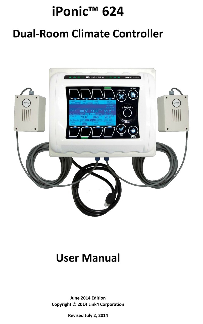
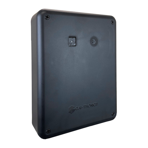
Link4 iGrow 100 Series User manual

iGrow 100 Series™
Installaon and User’s Manual
April 2012 Edion - Version 5.1

1iGrow Series 100 Manual
Contents
Introducon...................................................................................................................... 3
CustomerService................................................................................................................ 4
TermsandCondions......................................................................................................... 5
BeforeyouBegin................................................................................................................ 6
TemperatureControl............................................................................................... 6
Deadbands............................................................................................................... 7
Setpoints.................................................................................................................. 7
Ramping................................................................................................................... 7
ControlStrategy.................................................................................................................. 9
SetpointandStagingWorksheets............................................................................ 9
HardwareInstallaon....................................................................................................... 10
ContentInspecon................................................................................................ 10
RecommendedTools.............................................................................................. 10
MounngtheiGrowSeries100™.......................................................................... 10
iGrowSeries100™Overview............................................................................................ 12
OpeningtheiGrowSeries100™............................................................................ 12
InternalLayout....................................................................................................... 13
WiringtheiGrowSeries100™.......................................................................................... 14
PowerSupplyInstallaon...................................................................................... 14
OutputInstallaon................................................................................................. 15
ControlRelays&Contactors.................................................................................. 16
IndoorAirTemperatureProbeInstallaon............................................................ 17
Programming................................................................................................................... 19
BeforeYouBegin.................................................................................................... 19
iGrowSeries100™MainScreenLayout................................................................. 19
Navigaon.............................................................................................................. 20
StatusScreens........................................................................................................ 21
MainStatusScreens.................................................................................... 21
ProgrammingScreens................................................................................. 22
SetpointProgramming..................................................................................................... 23
Reports/Logs................................................................................................................... 28
ReturnonInvestment............................................................................................ 29
Graphing................................................................................................................ 30
EquipmentCosts.................................................................................................... 34
EnergyCosts........................................................................................................... 35
EquipmentUsage................................................................................................... 36
EnergyUsage......................................................................................................... 37
EventLogs.............................................................................................................. 38

iGrow Series 100 Manual2
SystemSetup.................................................................................................................... 40
EquipmentSetup................................................................................................... 41
GeneralType............................................................................................... 44
EnergyType................................................................................................. 50
AssignStages............................................................................................... 55
TemperatureStages..................................................................................... 56
HumidityStages.......................................................................................... 58
ResetRunme............................................................................................. 60
Save&Restore....................................................................................................... 61
Save&RestoreConguraons.................................................................... 62
SaveLogFiles.............................................................................................. 64
SensorSetup.......................................................................................................... 66
MapSensors................................................................................................ 67
CalibrateSensors......................................................................................... 68
SelfTestSetUp............................................................................................ 69
AnalogSensorMapping.............................................................................. 70
Time&DateSetup................................................................................................. 71
SetTime...................................................................................................... 72
SetDate....................................................................................................... 73
LocaonSetup....................................................................................................... 74
EnergyCost............................................................................................................ 75
CommunicaonSetup........................................................................................... 78
WeatherStaonSetup................................................................................ 79
IPAddressSetup......................................................................................... 80
MeasurementUnits............................................................................................... 81
Advanced............................................................................................................... 82
HumiditySengs........................................................................................ 83
ROISengs................................................................................................. 84
ClearAllData............................................................................................... 84
UnitInfo...................................................................................................... 84
StageDelay.................................................................................................. 85
BeginBootload............................................................................................ 85
UITest.......................................................................................................... 86
Password.................................................................................................... 86
Stages/Staging.................................................................................................................. 87
CompleteMenuStructureLisng..................................................................................... 88
ResengtheController................................................................................................. 108

3iGrow Series 100 Manual
Introduction
WelcometoiGrowSeries100™,Link4’sIntelligentGreenhouseEnvironmentalController.
TheiGrowSeries100™representsthelatestingreenhouseenvironmentalcontrolauto-
maon.iGrowSeries100™enablesyoutocontrolandintegrateavarietyofequipment
inyourgreenhouse.Yourheang,cooling,venng,shading,humidity,CO2,andlighng
needsarelinkedtogetherintooneexible,easy-to-usesystem.
Link4canoerreliableservicebecausewearestaedbythedesignerandengineersthat
developedtheiGrowSeries100™.IndesigningtheiGrowSeries100™itwasourpurpose
todesignacontrollerspecicallyforthedemandsandcostconcernsforsmalltomidsize
growersandnoothercontrollerhasabeerfeaturetopriceraothaniGrowSeries100™.
Yourgreenhousecontrolsystemshouldimprovethequalityandeciencyofyouropera-
on.iGrowSeries100™oersquickinstallaon,anddynamicprogrammingexibility
foreasierandmoreaccurategreenhousemanagementgivingyouthefreedomforyouto
focusonplantsandprots.
ThereasonwhywestandoutfromothersisbecauseofourLink4Promise:Ourpassion
istoprovidegrowerswithintelligentcontrolsoluons.Weunderstandcontrollingyour
growingenvironmentiscricaltoyoursuccess.Therefore,ourcommitmentistobuild
outstandingcontrollersandtoprovideexcellentsupportsothatyoucanknowwithcon-
dencethattheiGrowSeries100™systemisrightforyou.

iGrow Series 100 Manual4
Customer Service
Link4hasawell-trainedcustomersupportstathatisreadytohelp.Ourcustomer
servicecenteriscommiedtoyourgreenhousebusiness24/7throughourwebsite
orservicelineforaccesstosoluonsforyourcontrollerneeds.Beforeyoucontactus,
pleasewritedownthemodelnumberandserialnumberlocatedinsidetheiGrowSeries
100™enclosuresothatwecanserveyoubeer.
Address:
Link4Corporaon
22725LaPalmaAve
YorbaLinda,CA92887
Telephone:
SUPPORT866.755.LINK(5465)
Web:
www.link4corp.com
E-mail:
SALES sales@link4corp.com
SERVICE [email protected]om
ThereisextensiveonlinesupportforallLink4productsforregisteredusersat
www.link4corp.com.Registraonisprovidedatnocharge.

5iGrow Series 100 Manual
Terms and Conditions
Warranty
Link4warrantsthatthegoodssoldunderthiscontractwillbefreefromdefectsinmaterialandwork-
manshipforaperiodof12monthsaerthedateofpurchase.Thiswarrantywillbelimitedtothe
repairandreplacementofpartsandthenecessarylaborandservicesrequiredtorepairthegoods.IT
ISEXPRESSLYAGREEDTHATTHISWARRANTYWILLBEINLIEUOFALLWARRANTIESOFFITNESSAND
INLIEUOFTHEWARRANTYOFMERCHANTABILITY.
Moreover,anydescriponofthegoodscontainedinthiscontractisforthesolepurposeofidenfy-
ingthem,isnotpartofthebasisofthebargain,anddoesnotconstuteawarrantythatthegoods
willconformtothatdescripon.Theuseofanysampleormodelinconneconwiththiscontract
isforillustravepurposesonly,isnotpartofthebasisofthebargain,andisnottobeconstruedas
awarrantythatthegoodswillconformtothesampleormodel.Noarmaonoffactorpromise
madebyLink4,whetherornotinthiscontract,willconstuteawarrantythatthegoodswillconform
tothearmaonorpromise.
Link4shallnotberesponsibleforreplacement(s)orrepair(s)whichbecomedefecvefromuserneg-
ligence,modicaon,abuseand/oranytypesof improperusage.Nonconformancetoanyofthe
specicaonsintheproductmanualwillvoidthewarranty.Furthermore,ourliabilitytothegoods
sold,whetheronwarranty,contract,ornegligence,willbereleasedupontheexpiraonofthewar-
rantyperiodwhenallsuchliabilityshallterminate.
Link4 shall not be responsible for any loss or claims due to consequenal damages aord by the
Buyer.Link4alsoreservestherighttomakeanynecessarychangestofeaturesandspecicaonsto
condionorwarranty.
Returns
MerchandisecannotbereturnedwithoutaReturnMerchandiseAuthorizaon(RMA)numberfrom
Link4.Requestsforpermissiontoreturndefecveitemsmustbemadewithin(14)fourteendays
aerreceiptofshipment.ALink4RMA#forapprovedreturnsmustappearonboththecustomer’s
shippingcartonandtherelatedreceiptmemo.Partsunderwarrantywillberepairedatnocharge.
Otherreturneditemswillbesubjectedtothefollowingrestockingcharges:20%fornovalueadded
items,40%forvalueaddeditems,and75%forcustomdesignedorbuilttospecicaonitems.
Repair
ArepairordermustalsohaveaLink4ReturnMerchandiseAuthorizaon(RMA)number.Repairsthat
arenotcoveredbythewarrantywillbebilledonamaterialandlaborbasis.Itemsreturnedforrepair
mustbesenttoLink4withprepaidreturntransportaonLink4willnotberesponsiblefordamage(s)
duetoimproperpackagingorshippinganddeliveryofitemsreturnedforrepair.
Addional Costs
ItisexpresslyagreedthatBuyerwillreimburseLink4foranyaddionalcostsaributabletochanges
inthespecicaons,direcons,ordesignoftheitemsfurnishedwhicharerequestedorapprovedby
BuyeratLink4’slistedretailpricesineectatthemesuchchangesareordered.
Governing Law
Thevalidityofthiscontractandofanyofitstermsorprovisions,aswellastherightsandduesofthe
paresunderthiscontract,shallbeconstruedpursuanttoandinaccordancewiththelawofCalifor-
nia.TheparesspecicallyagreetosubmittothejurisdiconofthecourtsofCalifornia.

iGrow Series 100 Manual6
Before you Begin
Temperature Control
WiththeiGrowSeries100™youcanprogramacoolingtemperaturetargetcalleda“Cool
Setpoint”andaheangtemperaturetargetcalleda“HeatSetpoint”.Thetemperature
rangebetweenthesetwotargetsiscalledthe“Normal”temperaturerangeorstage.If
thegreenhousetemperatureiswithintheNormaltemperaturebandusuallynoneofthe
coolingorheangequipmentison.However,somecirculaonfans(oencalledhorizon-
talairow(HAF)fans)maybeacvetomaintainairmovementwithinthegreenhouse
environment.
Whenever the temperature within the greenhouse moves above the cool setpoint, or
belowtheheatsetpoint(fallsoutsidetheNormaltemperaturerange)theiGrowSeries
100™willentercoolingorheangstagestobringitbackinline.WiththeiGrowSeries
100™youcanprogramuptosixcoolingandtwoheangstages.Thesestagesgofrom
Cool1toCool6andHeat1toHeat2.Cool1andHeat1aretheleastaggressivewithCool
6andHeat2themostaggressive.Inyourprogramyouwilldeterminewhatequipment
youwanttobeacveineachofthestages.
WhentheairtemperatureinthegreenhouserisesabovetheCoolSetpoint,thesystem
enterstherststageofcooling,referredtoasCool1.Ifthetemperatureconnuestorise,
thesystemwillenterthesecondstage,Cool2,thenthethirdstage,Cool3andsoforth.
Ateachincreasingcoolingstage,morecoolingwillbebroughttoaempttobringtheair
temperaturebelowthecoolsetpointandwithinthetarget“Normal”temperaturerange.
Heangworksthesameway.
Inconsideringthedierencebetweeneachheangandcoolingstagethereisavariable
intheprogramwhichisthenumberofdegreesbetweeneachheangandcoolingstage
calledthe“StageSeparaon”or‘StageWidth”.Wheneverthetemperaturerisesabove
thecoolsetpoint,theiGrowSeries100™willacvatetheappropriateequipmenttobring
thegreenhousetothenormaltemperaturerange.Ifthestagewidthis1degreeandthe
temperaturerises1.1degreesabovethecoolsetpoint,thenthecontrollerwillbeacvein
C2coolingstage.Thesamegoesfortheheangstagewhenthetemperaturedropsbelow
theheangsetpoints.InFigure1.1,thereisanexamplewithfourcoolingstagesandtwo
heangstages.

7iGrow Series 100 Manual
Deadbands
Ifthetemperatureisbelowthecoolsetpointandrisesintotherststageofcooling,some
coolingequipmentwillbeturnedon.Thismaythenlowerthetemperatureandbringit
intothenormalrange.Inordertokeeptheequipmentfromoscillang,a“Deadband”is
employedwhenthetemperatureisbetweenstages.InFigure1.1thedeadbandisset
at1degreesothatwhenthegreenhouseisaempngtoreturntoNormaltemperature
fromC4toC3thecontrollerwilluseadeadbandof1degreetokeeptheequipmentfrom
oscillang o and on. Now, when the temperature drops below the cool setpoint, the
systemremainsintheCool1stageunlthetemperaturedropsbelowtheCoolDeadband.
Theconceptsthatwedescribedforcoolingoperateinthesamemannerforheang.
Setpoints
Youwillbeabletouseupto3setpointsina24hourmeperiod.Withineachtwenty-
fourhourperiodSetpointsarebasedonmeandtemperaturetoproducethedeisred
environment.Byplacingsetpointsduringdierentmesofthedayyoucanregulatethe
temperaturewithinarangefortargettemperaturesandhumidity(humiditysensorsold
seperately).Whenasetpointisineectatacertainmelengththecontrollerwillac-
vatethenecessaryequipmentinheangandcoolstagestobringtheenvironmentback
toNorm.Thesameapplieswhenthehumidityrisesorfallsbeyondthetargetlow/high
setpoint.Whenoneormoresetpointsareusedthesecondorsubsequentsetpointswill
becometheacvesetpointatthestartmeandtheprevioussetpointwillend.
Ramping
Inaddion,youhavetheoponofatemperaturerampbetweenthesetpoints.Eachset-
pointmeperiodbeginswithaRampme.Thebenetoframpingallowsyoutomake
smoothtransionswithinthegreenhousesothattheplantsdon’texperiencetempera-
tureshock.Ramping alsosavesenergy, whichtranslatesdirectlyintoloweroperang
costs.
Intheexampleonthefollowingpage(Figure1.1),thestartmeis8:00amwitha60min-
uterampme.Therampmeenablesasmoothtransionofthetargettemperatures
betweenthesetpointmeperiods.Ofcourse,therampmescanbesetto0andinthis
casetherewillbeanimmediatesteptransioninthesetpoints.Figure1.1alsoshowsa
typicalexampleofastagingworksheet.

iGrow Series 100 Manual8
Setpoint 1issetto8:00amwitha60minuteRamp,Tempissetas68to72.0°F
Setpoint 2issetto6:00pmwitha30minuteRamp,Tempissetas67to70.5°F
Figure 1.1 Example of Setpoints, Staging, & Deadbands
SET POINTS START TIME
DAY
6:00 AM
NIGHT
7:00 PM
DIF
NOT USED
EQUIPMENT
NAME
H2 H1 N C1 C2 C3 C4 C5 C6 De-H Hum
1RVM-1 ROOF VENT OPEN 20% 40% 60% 80% 99% 99% 15%
2RVM-1 ROOF VENT CLOSE
3SWM-1 SIDEWALL OPEN 0% 10% 80% 99% 99% 99% 0%
4SWM-1 SIDEWALL CLOSE
5EX-1 EXHAUST FANS ON ON ON ON
6HAF-1 HAF FANS ON ON ON ON ON ON ON ON ON ON
7HT-1 HEAT NORTH ON OFF
8HT-2 HEAT SOUTH ON ON
60
OUTPUTS
FOR ON/OFF & VENT ONLY
HEAT
STAGES
COOLING STAGES
HUMIDIFICATION
STAGES
68
55
72
65
30 55 80
55 80
TEMPERATURE
RAMP
TIME HUMIDITY
Low Set Pt.
(°F/°C)
High Set Pt.
(°F/°C) (min)
Low Set Pt.
(%)
High Set Pt.
(%)
12am 1 2 3 4 5 678 9 10 11 12pm 1 2 3 4 5 86 79 10 11
65° F
70° F
75° F
Setpoint 1
Day Cool
72.0° F
Setpoint 1
Day Heat
68.0° F
Setpoint 2
Night Cool
70.5° F
Beginning of
Ramp time
8:00am
End of
Ramp time
9:00am
Cool Stage 1
Cool Stage 2
Cool Stage 3
Cool Stage 4
Heat Stage 1
Heat Stage 2
Setpoint 2
Night Heat
67.0° F
End of
Ramp time
6:30pm
Beginning of
Ramp time
6:00pm
1° F Deadbands
SAMPLE WORKSHEET

9iGrow Series 100 Manual
Control Strategy
PriortoinstallingandprogrammingtheiGrowSeries100™itisimportanttodeterminean
overallstrategytocontroltheenvironmentinthegreenhouse.TheiGrowSeries100™is
anextremelyexibleandpowerfuldevice,thusaddionalcareandplanningarerequired.
Inordertoaidyouwiththeprocess,Link4hasprovidedseveralworksheetsinthefollow-
ingpages.Itisassumedthatyoualreadypossessageneralunderstandingofgreenhouse
controls.Ifnot,pleasereviewthisseconcarefully.
Itisrecommendedthatyoumakecopiesofthesesheetsbeforeusingthem.Theywillbe
usefulinthefutureshouldyourcontrolneedschange.
Setpoint and Staging Worksheets
Figure 1.2 Setpoint & Staging Worksheets
SET POINTS START TIME
DAY
NIGHT
DIF
EQUIPMENT
NAME
H2 H1 N C1 C2 C3 C4 C5 C6 De-H Hum
1
2
3
4
5
6
7
8
OUTPUTS
COOLING STAGES
Low Set Pt.
(%)
High Set Pt.
(%)(min)
TEMPERATURE
Low Set Pt.
(°F/°C)
High Set Pt.
(°F/°C)
HEAT
STAGES
HUMIDIFICATION
STAGES
FOR ON/OFF & VENT ONLY
RAMP
TIME HUMIDITY

iGrow Series 100 Manual10
Hardware Installation
Content Inspecon
ThepackageshouldcomecompletewithaniGrowSeries100™unit,a12VDCpowersup-
ply,atemperaturesensorprobewith50’ofcableaached,and4–SelfDrillingScrews.
Uponarrival,checkthecontentswiththepackinglistfordamagedormissingcomponents
(IfyouhavetheIntegratediGrow100SeriesModel,simply mountthepanelusingthe
mounngfeetprovided).
Addionalaccessoriessuchasdigitaltemperature/humiditysensor,outsidetemperature
sensor,lightsensor,windandrainsensorscanbepurchasedandaddedatanyme.
Make sureyouhaveallitems,allassociatedhardware,andnecessarytoolsbeforeyou
begininstallaon.Ifthereisanyvisibledamageormissingparts,pleasecontactourcus-
tomerserviceat[email protected]omor1-866-755-LINKorfaxusat714.558.9782.
1. iGrowSeries100™unit
2. 12VDCexternalPowerSupply
3. Temperatureprobewith50.cable
4. 4pcs–PhilipsHeadSelfDrillingScrews
5. 4pcs–3/8”Drive,HexHeadSelfDrillingScrews(integratedopononly)
Recommended Tools
1. Drill
2. 1/8”highspeedsteeldrillbit
3. Phillipsheadscrewdriver
4. Level(oponal)
5. Pencil
Mounng the iGrow Series 100™
1. First,nda securelocaontomount theiGrowSeries 100™ controller. The area
shouldbeawayfromdirectsunlight,condensinghumidity,water,rain,orextreme
temperatures. Itshould bemountedin aneasily accessiblelocaonatthe user’s
eyelevel.
2. Sincethe iGrowSeries100™ isequipped with ahingeddoor and ahingedaccess
panelforeasyserviceandinstallaon,makesurethereisadequateworkspace.The
recommendedclearanceis8”fromeachsideofthecontrolunit.

11iGrow Series 100 Manual
3. TheiGrowSeries100™comeswitha12VDCwallmountpowersupply.Makesure
there is a power outlet within approximately 6 feet. It is recommended that the
outletisnotswitchedandisonacircuitthatisindependentofanynoisy,highpower
equipment.Theuseofasealedoutletisrecommendedifthepoweroutputisex-
posedtomoisture.
4. Idenfy what type of surface you will be mounng the iGrow Series100™ to. In-
cludedare4self-drillingscrewsformounngtobeamorwoodpanel.
5. Thereare4mounngpointsontheinsideoftheiGrowSeries100.Usingtheappro-
priatetoolsdependingonyoursurface,mounttheiGrowSeries100™.Refertothe
gurebelow(2.1)foravisualpicture.
Figure 2.1 iGrow Series 100™ Installaon Instrucons

iGrow Series 100 Manual12
iGrow Series 100™ Overview
NowthattheiGrowSeries100™hasbeenmounted,takesomemetolookoverthefront
panel.TheiGrowSeries100™hasmanyfeaturestohelpgiveyouthegrowingadvantage.
Figure2.2belowgivesanoverviewofthemaincomponentsthattheiGrowSeries100™
hastooer.
Figure 2.2 Front View of iGrow Series 100™
Opening the iGrow Series 100™
Openthehingeddoorbysimultaneouslydepressingonthetwosideejectorbuonswith
yourthumbs,whileusingyourmiddleandindexngersforsupport.
Figure 2.3 Proper nger posions for door opening

13iGrow Series 100 Manual
Internal Layout
Figure2.4showshowtheiGrowSeries100™looksontheinside.Takenoceoftheboard
andfamiliarizeyourselfwiththeinternallayoutbeforebeginningthewiringprocess.
Figure 2.4 Internal Layout of the iGrow Series 100™ PCB
8 Relay Output
Terminal Pairs
Optional
Communications
Module
DC Input
Power
Inside Temperature Sensor
for use with provided Temperature Probe
Temperature / Humidity Sensor
for use with optional Temp/Humidity Sensor
Weather Station
Inputs
Backup Battery
Master Reset
Button
Manual Override
Switches
Analog InputsUSB Storage
Input
Contrast Adjustment
for Front Panel Display
RJ45 Connector
for PC Connectivity

iGrow Series 100 Manual14
Wiring the iGrow Series 100™
Warning: Do Not Plug-in the Power while wiring the iGrow Series 100™ and keep the
manual override switches in the OFF posion.
Itisrecommendedthatallconneconsbemadethroughliquidghtconnectorsatthe
boomoftheiGrowSeries100™.Theseglandscompressaroundthecablestoforma
waterghtseal.Makinganyaddionalholesinthetop,sides,orbackoftheenclosure
canresultinwatercondensaoninsidetheunit,causingdamagetothecontroller.Failure
toinstalltoLink4’sspecicaonwillvoidthewarranty.
InpreparaonforthecontrolwiringyoushoulddecidetheiGrowSeries100™outputas-
signmentsandcontrolstrategy.Formoreinformaononoutputassignmentandcontrol
strategies,pleaserefertotheControlStrategyseconandtheappropriateworksheets
forthismanual.
Power Supply Installaon
1. IfyouwanttonavigatethroughtheiGrowSeries100™toseesomeofthefeatures
andtofamiliarizeyourselfwithhowitworks,beginbyinstallingthepowersupply.
MakesurethepowersupplyisNOTpluggedinwhileinstallinganyotheroutputsor
inputs.
2. BeginthepowerinstallaonbymeasuringthedistancebetweenwheretheiGrow
Series100™ismountedandthepowersocket.Thereneedstobeabout6feetbe-
tweenthetwo.Ifthepowersupplyistooshort,thenuseapowerextensioncord.
Note:extensioncordisrecommendedfortemporaryusageonly.
3. Makesureall8manualtoggleswitchesareintheOFFposion.
4. Taketheopenend(thetwostrippedandnnedleads)ofthepowersupply.TheRED
leadisthe12VDCpowerandtheBLACKleadistheGND(ground).Routethepower
leadthroughthelemostliquidghtconnector.Remembernottopluginthepower
supplyatthisme
5. LocatetheDCInputPowerterminalonthePCB.SeeFigure2.4andFigure3.1.
6. ConnecttheGroundlead(BLACK)totheGNDterminalusinga#0screwdriver.Make
suretomakeitasnugt.Alsotakecarenottoover-ghtentheconnecon.
7. Thesameprocessisusedtoconnectthe12Vpowerlead(RED)tothe12Vterminal
usinga#0atdrivescrewdriver.

15iGrow Series 100 Manual
8. Now, if needed, you can plug in the power to navigate through the iGrow Series
100™.Ifyouconnuetoinstalldierentoutputsorinputsremembertokeepthe
powersupplyunplugged.
Figure 3.1 Wiring the Power Supply
Output Installaon
Thegeneralinstallaonstrategyforthisseconistoinstalltheoutputequipmentinthe
greenhouse rst and then the inputs to keep the cables organized in the iGrow Series
100™.Itisassumedthatatthispointyouhavealreadyplannedthechannelassignment.
Ifyouhavenot,pleasereferbacktoControlStrategy(page9).
AllcablescomingintoandoutoftheiGrowSeries100™shouldgothroughtheliquidght
connectorsattheboomoftheenclosure.Inordertominimizeinterference,itisrecom-
mendedthatthesensorinputwiresnotberoutedthroughthesameconnectorasthe
controlpower.Forbestresults,routeallsensorwiresthroughthelemostliquidght
connectorandthenmovetowardtheright.Thepowerwiresandnon-sensorwiresare
routedthroughtherightmostconnector,andifneeded,thenextconnectorover.

iGrow Series 100 Manual16
Control Relays & Contactors
YouriGrowSeries100™has4or8outputrelaysthatareprovidedasdrycontacts,i.e.
switchclosures.IfanoutputisacvatedtoON,theswitchis“closed”(shorted);andifit
isacvatedtoOFF,theswitchis“open”(noconnuitybetweentheposiveandnegave
terminals).
Theboardmountedrelaysareintendedas“pilot”relays.Formostloadsyouwillwant
theiGrowSeries100™outputstocontrolaloadrelayorcontactorthatisconnectedto
themotor.However,insomecasessuchasirrigaonvalvesthatare24VAC,youcandrive
themdirectlyassumingthatyouarewiringonlyoneortwovalvesperrelay.Themaxi-
mumruncurrentrecommendedforeachoftheiGrowSeries100relaysis1amp.
“Dry” Contact Design
“Dry”contactinstallaondesignisusedwhenauserwantstoisolateequipmentanduse
transformersforeverypieceofequipment.
Figure 3.2 Output Wiring Example

17iGrow Series 100 Manual
Indoor Air Temperature Probe Installaon
TheiGrowSeries100™ isshippedwithastandardtemperatureprobe.This sensorin-
cludes50-feetofsensorcable.Normallyyouwillwanttohangthesensornearthecrop
levelclosetothecenterofthecontrolledenvironment.Itisimportanttokeepthesensor
awayfromirrigaonemiers,unitheaters,etc.thatwilleecttheaccuracyofthesensor.
1. First,openupthefrontdoor,asshowninFigure2.3.
2. Findacentrallocaoninthegreenhouseandletithangrelavelyclosetotheheight
ofwheretheplantswillbe.
3. Runthefreeendofthesensorcabletothecontrollerunit.
4. Youmayextendthesensorcableasneeded,butmakesuretouseanadapterand
wireapprovedbyLink4tomakeanyextensions(thewireandadaptercanbepur-
chasedfromLink4).Itshouldbenotedthatthecontrolleriscalibratedfora50.
temperatureprobe.Ifaddionalwiresareaddedorremoved,sowarecalibraon
willbenecessarytoensurepropertemperaturemeasurementaccuracy.
5. Carefullyinsertthecablethroughtherightmostwaterghtngattheboomof
theenclosure.Itiseasytostripinsulaonand/orbreakwireswhenpullingcable.
Ifyouwanttobundlewiresghter,useUVprotected“ewraps”(typicallyblueor
black),anddonotover-ghten.
Note: If any splices are needed to extend cable length, make certain they are WATERTIGHT.
Water or ferlizer inltraon WILL cause unstable sensor readings.
6. ConnectthewiresasshowninFigure3.3.
7. Keep sensor cables away from interference sources, including high voltage power
wiring,inverters,motorcontrollers,mercuryarc,orsodiumlampcircuits.Placing
sensorcablenearsuchwiringmaycauseerracsensorreadings.
8. Aerinstallingthesensor,itisrecommendedthatsensorsbecheckedbypluggingin
thepowersupplyandtesngundervariouscondionsbeforemovingoninorderto
makesurethesensorworksproperlyandaccurately.Testthetemperaturebychang-
ingtheindoortemperaturetoseeifitisreadingproperly.Aertesngrememberto
unplugtheunittoconnueinstallingothersensors.

iGrow Series 100 Manual18
Figure 3.3 Wiring iGrow 100 Series Sensors

19iGrow Series 100 Manual
Programming
Before You Begin
BeforetheiGrowSeries100™isprogrammed,itisrecommendedthatthefollowingsteps
arefollowed:
• Hardwareisproperlyinstalledandtestedwithmanualswitches.
• AllinternalswitcheshavebeenrestoredbacktotheOFFstate.
• AllthetemplatesfromtheControlStrategychapterthatarerelevanttoyourapplica-
onareunderstoodandarecompletelylledout.
iGrow Series 100™ Main Screen Layout
(Note:TheROIscreenwouldonlyappearatthisleveloncetheenergyinformaonhas
beenprogrammed.)
HOME/BACK
MENU
Table of contents
Other Link4 Temperature Controllers manuals
