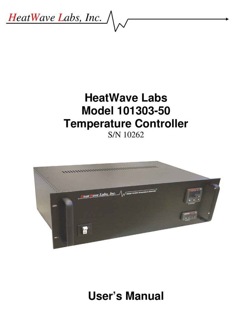
Solid State Cooling Systems TCS-110 User manual

Preliminary
Product Manual
TCS-110
Precise, uniform surface temperature with integrated controller
Microtiter Temperature Control Stage

TCS-110 TEMPERATURE CONTROL STAGE PRODUCT MANUAL 52-13129-1
SOLID STATE COOLING SYSTEMS,167 MYERS CORNERS ROAD,WAPPINGERS FALLS,NY 12590 1
TELEPHONE:(845) 296-1300 FAX:(845) 296-1303 WEB:WWW.SSCOOLING.COM VERSION E6
Table of Contents
SAFETY PRECAUTIONS AND SYMBOLS ____________________________________________2
SECTION 1 ________________________________________________________________________3
INTRODUCTION ____________________________________________________________________3
SECTION 2 ________________________________________________________________________4
PRELIMINARY SPECIFICATIONS ________________________________________________________4
SECTION 3 ________________________________________________________________________6
HOOK UP_________________________________________________________________________6
3.1 Mechanical Installation _______________________________________________________ 7
3.2 Electrical Installation/Connections (see figure 3A) __________________________________ 8
SECTION 4 ________________________________________________________________________9
START UP_________________________________________________________________________9
4.1 Start-up when connected directly to a PC:_________________________________________ 9
4.2 Start-UP when connected to a PC through a Router or a Server________________________ 9
SECTION 5 _______________________________________________________________________16
OPERATION ______________________________________________ _______________________18
SECTION 6 _______________________________________________________________________20
SYSTEM ALARMS/TROUBLESHOOTING _________________________________________________20
SECTION 7 _______________________________________________________________________20
CLEANING YOUR CHILLER ___________________________________________________________20
SECTION 8 _______________________________________________________________________20
TECHNICAL SUPPORT_______________________________________________________________20
WARRANTY POLICY _____________________________________________________________21

TCS-110 TEMPERATURE CONTROL STAGE PRODUCT MANUAL 52-13129-1
SOLID STATE COOLING SYSTEMS,167 MYERS CORNERS ROAD,WAPPINGERS FALLS,NY 12590 2
TELEPHONE:(845) 296-1300 FAX:(845) 296-1303 WEB:WWW.SSCOOLING.COM VERSION E6
SAFETY PRECAUTIONS AND SYMBOLS__________________
Caution! Burn and Freeze Hazard!
The TCS-110 microtiter temperature control surface
temperatures can range from 0°C to 110°C. Do not
touch the top surface while in operation!
Symbols Used in this Manual
The red CAUTION equilateral triangle symbol appears throughout
the manual. Please follow the important instructions
accompanying this symbol to avoid significant damage to the
chiller.
The red WARNING equilateral triangle symbol appears
throughout the manual accompanying certain maintenance and
repair activities. Please follow the important instructions
accompanying this symbol to avoid situations that could cause
injury to the operator or other personnel.
The red DANGER equilateral triangle symbol appears throughout
the manual accompanying certain maintenance and repair
activities. Please follow the important instructions accompanying
this symbol to avoid injury to the operator. Only trained
personnel should undertake any activity marked by the red
DANGER triangle.
CAUTIONS
▪Safe operation the TCS-110 requires earth ground be connected to Pin. Do Not Operate the
TCS-110 without proper grounding!
▪Operation of the TCS-110 in any manner not recommended in this manual could compromise the
safety of operating personnel.
▪Never disassemble the TCS-110 unit as irreparable damage may occur.
CAUTION
DANGER
WARNING

TCS-110 TEMPERATURE CONTROL STAGE PRODUCT MANUAL 52-13129-1
SOLID STATE COOLING SYSTEMS,167 MYERS CORNERS ROAD,WAPPINGERS FALLS,NY 12590 3
TELEPHONE:(845) 296-1300 FAX:(845) 296-1303 WEB:WWW.SSCOOLING.COM VERSION E6
TCS-110 MICROTITER TEMPERATURE CONTROL STAGE
SECTION 1
INTRODUCTION_________________________________________________
The TCS-110 provides a temperature controller platform for all
ANSI SBS 2004-1 microwell plates. It features a built-in controller
and DC power management to provide uniform surface
temperature with high heat transfer rates to repeatably control the
temperature of microwell plates from 0°C to 110°C. No separate
controller is necessary. The TCS-110 features a TCPIP Ethernet
interface allowing multiple units to be connected to the host tool.
It may be mounted either on top of a deck or integrated into a deck
surface via an interface fixture. SSCS can customize interface
fixture to meet your specific needs.
The complete system includes an external, universal 24VDC DC
power supply and power cord.

TCS-110 TEMPERATURE CONTROL STAGE PRODUCT MANUAL 52-13129-1
SOLID STATE COOLING SYSTEMS,167 MYERS CORNERS ROAD,WAPPINGERS FALLS,NY 12590 4
TELEPHONE:(845) 296-1300 FAX:(845) 296-1303 WEB:WWW.SSCOOLING.COM VERSION E6
SECTION 2
PRELIMINARY SPECIFICATIONS ___________________________________
Operating Range: 0°C to 110°C
Ambient Temperature Range: 10°C to 40°C non-condensing
Stability / Repeatability: ±0.1°C with constant load (even near ambient)
Temperature Uniformity: ±0.5°C @ 37°C in 22°C ambient
Temperature Ramp Rates2: Average heating ramp rate from 4°C to 99°C = 0.3°C per second
Average cooling ramp rate from 4°C to 99°C = 0.2°C per second
Communications: Ethernet 3
Alarms: Fan fail, RTD fail, Temperature out of range
Dimensions:
Top Plate: 3.590” x 5.245” (ANSI/SBS 1-2004 microplate standard)
Overall Above deck (W x L x H): 6.45" x 4.29" x 1.38" (16.3 x 10.9 x 3.5 cm) - with collar
Overall Below deck (W x L x H): 5.66" x 3.27" x 4.35" (14.4 x 8.3 x 11.0 cm)
Weight: 4 lbs (1.8 kg) without external power supply
DC Operating Voltage: 24 VDC, 8 amps DC max
External Power Supply Input: Universal: 100-240 VAC, 50/60 Hz, 4 amps max
Standards: RoHS 3, ANSI/SBS 1-2004,
UL, CAN/CSA and EN 61010-1, CE 61010-1 (Pending)
Warranty: 2 years
Notes:
1. All specs are preliminary and are subject to change after Beta testing is completed.
2. Ramp rates shown are typical, measured without inserts.
3. Each stage has a unique TCPIP address. There is no limit to the number of stages.

TCS-110 TEMPERATURE CONTROL STAGE PRODUCT MANUAL 52-13129-1
SOLID STATE COOLING SYSTEMS,167 MYERS CORNERS ROAD,WAPPINGERS FALLS,NY 12590 6
TELEPHONE:(845) 296-1300 FAX:(845) 296-1303 WEB:WWW.SSCOOLING.COM VERSION E6
SECTION 3
HOOK UP______________________________________________________
Figure 2: Front View
Figure 2: Rear View
Input DC Power Connector
Ethernet Connector
Air Inlet
Air Outlet
Air Outlet

TCS-110 TEMPERATURE CONTROL STAGE PRODUCT MANUAL 52-13129-1
SOLID STATE COOLING SYSTEMS,167 MYERS CORNERS ROAD,WAPPINGERS FALLS,NY 12590 7
TELEPHONE:(845) 296-1300 FAX:(845) 296-1303 WEB:WWW.SSCOOLING.COM VERSION E6
3.1 MECHANICAL INSTALLATION
Mounting:
The TCS-110 is designed for mounting to a deck via an interface
bracket as shown in figure 3 below. Alternatively. The TCS-110 feet
have four (4) mounting holes at the bottom for mounting from below
using M3 screws.
Figure 3: Mechanical Layout without Collar
Figure 4: Robot Alignment Witness Mark
Robot Witness Mark
The TCS-110 comes with a witness mark for robot
alignment, see figure 4.
Air Considerations:
Good airflow is essential to the operation of the TCS-
110. The air intake is from the bottom and exits out
the left and right sides (see Figure 2). Do not block
airflow into or out of the TCS-110. SSCS
recommends maintaining 2” of clearance around the
air inlets (front and back sides at the bottom) and out
the left are right sides
.

TCS-110 TEMPERATURE CONTROL STAGE PRODUCT MANUAL 52-13129-1
SOLID STATE COOLING SYSTEMS,167 MYERS CORNERS ROAD,WAPPINGERS FALLS,NY 12590 8
TELEPHONE:(845) 296-1300 FAX:(845) 296-1303 WEB:WWW.SSCOOLING.COM VERSION E6
3.2 ELECTRICAL INSTALLATION/CONNECTIONS (SEE FIGURE 3A)
The TCS-110 comes with a 220w universal, external DC power
supply (brick) with the DC power connector that plugs into the TCS-
110, it ships with a regional AC power cord
A wide variety of power cords are available to support universal
power operation:
Table 1: Power Cord Part Numbers
Country / Region
Part Number
USA/Canada
22-22333-1
Europe
22-22333-2
Japan
22-22333-3
UK
22-22333-4
Israel
22-22800-1
Australia
22-23213-1
Korean
22-23526-1
China (3 prong)
22-23661-1
Brazil
22-25122-1
India/South Africa 6A (Type D)
22-26025-1
India/South Africa 15A (Type M)
22-26025-2
NEMA 6-15 208 US Straight
16-23918-1
NEMA L6-15 208 US Twist
16-23918-2
Power: The TCS-110 has a Molex Mini-Fit BMI 4204 series
connector for DC power and ground, 24VDC power may be
connected directly into the TCS-110 via this connector:
Molex PN: 0015246040
Mating Molex Connector: Mini-Fit Jr. series 5557
PN: 0039013042
Pin-out:
Pin 1- Chassis Ground
Pin 2- +24V DC
Pin 3- DC(-) (return)
Pin 4- Not Used
Fuses:
Controller: 0.5amp (5mm x 20mm) GDB quick acting glass, meets
IEC 127-2
Replacement Fuse: SSCS#, Allied Electronics
Remote Communication: The TCS-110 is controlled though the
Ethernet port on the Front panel. This port is a standard RJ-45 jack.
For more information, refer to section 7.1.
Electrical Shock
Hazard: Never Plug
in a Line Cord with
Wet Hands
WARNING

TCS-110 TEMPERATURE CONTROL STAGE PRODUCT MANUAL 52-13129-1
SOLID STATE COOLING SYSTEMS,167 MYERS CORNERS ROAD,WAPPINGERS FALLS,NY 12590 9
TELEPHONE:(845) 296-1300 FAX:(845) 296-1303 WEB:WWW.SSCOOLING.COM VERSION E6
SECTION 4
START UP _____________________________________________________
The TCS-110 is operated via TCPIP Ethernet; its default settings are
as follows:
IP Address: 192.168.1.88
Subnet Mask 255.255.255.0
Gateway: 192.168.1.1
IP Configuration Static
Password admin
Port Number 10001
4.1 START-UP WHEN CONNECTED DIRECTLY TO A PC:
1) Plug the 24VDC power supply into your AC wall outlet or connect
24VDC to the TCS-110 as per section 3.2
2) Connect your CAT-5 Ethernet Cross-Over Cable to the TCS-110 RJ-
45 ethernet jack. Set your computer to a static IP address in this
range: 192.168.1.2-254 excluding 88.
3) Set your Subnet Mask to 255.255.255.0 and Gateway to 192.168.1.1.
4) The TCS-110 is now ready for operation. See section 4.3.
4.2 START-UP WHEN CONNECTED TO A PC THROUGH A ROUTER OR A SERVER
1. Plug the 24VDC power brick into your AC wall outlet or connect 24VDC to the TCS-110 as per
section 3.2.
2. Connect a standard CAT-5 Ethernet cable from the computer to the router, and another standard
CAT-5 Ethernet cable from the router to the TCS-110 RJ-45 Ethernet jack.
3. On the final test sheet provided upon shipment of the TCS-110 unit, find the IP address that has
been assigned to the unit. This address can be used in Section 4.3 to connect with the graphical
user interface.
4.3CONNECTING WITH SSCS GRAPHICAL USER INTERFACE
Solid State Cooling has developed a graphical user interface, or GUI, to be used to communicate with
the TCS-110 easily. For more information on the GUI and how to acquire it, contact the Sales
department at Solid State Cooling. If you do not wish to use this GUI, proceed to Section 5. (Note:
Establishing an Ethernet connection requires the use of the GUI.)
The following is an explanation of how to use the GUI to connect to the TCS-110 only after executing
either Section 4.1 or Section 4.2.
CAUTION
Do Not Change the
UART Settings. The
TCS-110 will not
operate if you do.

TCS-110 TEMPERATURE CONTROL STAGE PRODUCT MANUAL 52-13129-1
SOLID STATE COOLING SYSTEMS,167 MYERS CORNERS ROAD,WAPPINGERS FALLS,NY 12590 10
TELEPHONE:(845) 296-1300 FAX:(845) 296-1303 WEB:WWW.SSCOOLING.COM VERSION E6
1. Open the GUI and click on the “Com Setup” button on the yellow taskbar at the top of the GUI.
2. In the “Ethernet Setup” section of the Com Setup window, enter “10001” in the Port # box. If
you are connected to the unit directly from your computer, enter “192.168.1.88” in the TCP
Client Address box. If you are connected to the unit through a router or server, enter the IP
address of the TCS-110 which is specified in the final test sheet that was shipped along with the
unit.
Figures 5 & 6: Com Setup for Direct Connection (above), for Router/Server Connection (below).
3. Click “Connect”. If a window appears saying “Connection Established”, proceed to Step 4. If
this does not occur, your computer has assigned a new IP address to the TCS-110. To find what
this address is, see Section 4.5.1 for help troubleshooting the Ethernet connection.
4. Close out of the Com Setup window and in the upper-left hand corner of the GUI, click “OPEN”.
A window will momentarily appear saying “Downloading Controller Data… Please Wait”, after
which the TCS-110 will commence communication with the GUI and data will appear on the
GUI.

TCS-110 TEMPERATURE CONTROL STAGE PRODUCT MANUAL 52-13129-1
SOLID STATE COOLING SYSTEMS,167 MYERS CORNERS ROAD,WAPPINGERS FALLS,NY 12590 11
TELEPHONE:(845) 296-1300 FAX:(845) 296-1303 WEB:WWW.SSCOOLING.COM VERSION E6
Figure 7: Fully Populated Graphical User Interface (GUI)
4.4 GUIDE TO USING GRAPHICAL USER INTERFACE
This guide to using the TCS-110 graphical user interface, or GUI, consists of three parts:
•4.4.1: Pictures of GUI Components
•4.4.2: Explanations for Performing Common Tasks with GUI
•4.4.3: List of Nonfunctional Parameters
4.4.1 Pictures of GUI Components
Figure 8: Top-of-Screen Taskbar
Figure 9: Process Variables

TCS-110 TEMPERATURE CONTROL STAGE PRODUCT MANUAL 52-13129-1
SOLID STATE COOLING SYSTEMS,167 MYERS CORNERS ROAD,WAPPINGERS FALLS,NY 12590 12
TELEPHONE:(845) 296-1300 FAX:(845) 296-1303 WEB:WWW.SSCOOLING.COM VERSION E6
4.4.1 Pictures of GUI Components (continued)
Figure 10: Operating
Figure 11: System Params
Figure 12: System Config

TCS-110 TEMPERATURE CONTROL STAGE PRODUCT MANUAL 52-13129-1
SOLID STATE COOLING SYSTEMS,167 MYERS CORNERS ROAD,WAPPINGERS FALLS,NY 12590 13
TELEPHONE:(845) 296-1300 FAX:(845) 296-1303 WEB:WWW.SSCOOLING.COM VERSION E6
4.4.1 Pictures of GUI Components (continued)
Figure 13: Chiller Status/Faults
Figure 14: Board ID
4.4.2 Explanations for Performing Common Tasks with GUI
•Running the TCS-110
oPress the red STBY (run) button in the Operating component (Figure 10) to run the unit.
•Change the setpoint
oEnter a new value in the “Setpoint” box in the Process Variables component (Figure 9)
and press the Pbutton next to the box.
•Get Rid of Warnings/Faults
oOnce the issue causing the fault has been resolved, click the Clear Alarm button in the
Operating component (Figure 10) to cause the GUI to stop displaying a warning or fault.
•Graph TCS-110 Performance
oClick the Wonderful Graph button in the Operating component (Figure 10) to open the
following window:

TCS-110 TEMPERATURE CONTROL STAGE PRODUCT MANUAL 52-13129-1
SOLID STATE COOLING SYSTEMS,167 MYERS CORNERS ROAD,WAPPINGERS FALLS,NY 12590 14
TELEPHONE:(845) 296-1300 FAX:(845) 296-1303 WEB:WWW.SSCOOLING.COM VERSION E6
Figure 15: Graph Window
4.4.2 Explanations for Performing Common Tasks with GUI (continued)
•Graph TCS-110 Performance (continued)
oPress the Start Graph button to start graphing the parameters to the right of the button
that are checked. To change the range of the Y-axis, change the Ymin and Ymax values
next to either of the two Enter Range buttons and click the corresponding button to set a
new range.
oTo save the data that is graphed, press the Stop/Pause button to pause the graph and then
press the Save To Disk button to save a .csv file containing the parameters which were
graphed.
•Change Maximum % Heating/Cooling
oEnter a new value in the “%Max Heat” or the “%Max Cool” box in the System Params
component (Figure 11) and click the P button next to the box.
•Display Temperature in Two Decimal Points
oClick the “2 Dec Pts” checkbox in the System Config component (Figure 12) and press
the Pbutton next to the CFG1A box. To change the temperature back to 1 decimal point,
uncheck this box and press the same Pbutton.

TCS-110 TEMPERATURE CONTROL STAGE PRODUCT MANUAL 52-13129-1
SOLID STATE COOLING SYSTEMS,167 MYERS CORNERS ROAD,WAPPINGERS FALLS,NY 12590 15
TELEPHONE:(845) 296-1300 FAX:(845) 296-1303 WEB:WWW.SSCOOLING.COM VERSION E6
4.4.3 List of Nonfunctional Parameters
The following is a list of parameters on the GUI whose functions are not yet fully implemented, and will
thus be unusable. Each parameter is listed within the GUI component it is found in. Section 4.4.1 can be
used to locate each component.
Top-of-Screen-Taskbar (Figure 8):
•Get Configuration
•Calibration
•Test Programs
Process Variables (Figure 9):
•TE Current (A)
•Fan Current (A) (NOTE: Value displayed by GUI must be divided by 10 to get correct reading. For
example, if GUI displays Fan Current of 1.9 A, the actual reading is 0.19 A)
•Ambient
•Lid Temp Ctl Setpoint/Temp
System Params (Figure 11):
•Lid Heater min
•Lid Heater max
•Lid Heater Hysteresis
System Config (Figure 12):
•Allow Autotune
Chiller Status/Faults (Figure 13):
•Autotune Mode
•TE Current Low
Board ID (Figure 14):
•Product
•Program Controller
•Model Num
•Revision
•Serial Number
•Archive Model No. ?
•Archive Serial No. ?
•Refresh GUI mod/sn Database

TCS-110 TEMPERATURE CONTROL STAGE PRODUCT MANUAL 52-13129-1
SOLID STATE COOLING SYSTEMS,167 MYERS CORNERS ROAD,WAPPINGERS FALLS,NY 12590 16
TELEPHONE:(845) 296-1300 FAX:(845) 296-1303 WEB:WWW.SSCOOLING.COM VERSION E6
4.5 TROUBLESHOOTING
The following section details steps on solving problems that may arise during operation of the TCS-110.
•4.5.1: Unable to Connect to TCS-110 Via Router
•4.5.2: Ethernet Connection Lost
4.5.1 Unable to Connect to TCS-110 Via Router
This section is intended for those who are connected to the TCS-110 with a router and are unable to
use the graphical user interface to establish a connection. When using a router to connect your
computer to the TCS-110, it is possible for the computer to assign the TCS-110 unit a different
Ethernet address than the one assigned during production by Solid State Cooling. If this occurs, use
the following steps to find the newly assigned IP address.
1. If you know the IP address of the router being used, proceed to Step 2. If not, open the
application “Command Prompt” on your computer and enter the command “arp -a”, as
pictured below. Determine which of internet addresses belongs to the router by finding the
corresponding physical address which matches the physical address of the router.
Figure 16: Using Command Prompt to Find IP Address of TCS-110
2. Open a web browser such as Google Chrome or Microsoft Edge, type the router’s IP address
into the URL bar of the browser and press Enter. The page which appears will be specific to
the router being used.
3. Navigate the webpage to find the router’s DHCP clients table. On the table, find the device
whose name starts with “W7500S2E-R1-…”. The IP address that corresponds with this
device in the table is the new IP address of your TCS-110 unit.

TCS-110 TEMPERATURE CONTROL STAGE PRODUCT MANUAL 52-13129-1
SOLID STATE COOLING SYSTEMS,167 MYERS CORNERS ROAD,WAPPINGERS FALLS,NY 12590 17
TELEPHONE:(845) 296-1300 FAX:(845) 296-1303 WEB:WWW.SSCOOLING.COM VERSION E6
4. Use this IP address to connect with the GUI as specified in Section 4.3.
4.5.2 Ethernet Connection Lost
It is possible that during operation of the TCS-110, communication can be halted between the computer
and the unit. This may occur due to a fault in the router or Ethernet cables being used, or if the user
makes a change that the graphical user interface cannot process in time. For example, changing the
setpoint while the unit is running and the user is graphing the unit’s performance may occasionally cause
a break in communication. This problem will manifest itself in multiple ways: the Rcvd Data text box in
the COM Control component will not display anything, and parameters such as the Temp and %TE
PWM will no longer update. In order to reestablish connection if this occurs, try the following steps in
this order.
1. Close out the GUI and reopen it following the steps outlined in Section 4.3.
2. If this does not work, perform a power cycle on the TCS-110 and then try to connect with the
GUI using Section 4.3.
3. If this does not work and you are using a router to communicate, perform a power cycle on the
router. Doing so may result in the TCS-110 being assigned a new IP address, which will
necessitate using Section 4.5.1 above to find the newly assigned address. Once this address is
found, attempt to connect to the unit with the GUI using this new address.
4. If this does not work, contact Technical Support at Solid State Cooling Systems for more help.

TCS-110 TEMPERATURE CONTROL STAGE PRODUCT MANUAL 52-13129-1
SOLID STATE COOLING SYSTEMS,167 MYERS CORNERS ROAD,WAPPINGERS FALLS,NY 12590 18
TELEPHONE:(845) 296-1300 FAX:(845) 296-1303 WEB:WWW.SSCOOLING.COM VERSION E6
SECTION 5
OPERATION ______________________________________________ _____
The TCS-110 is operated via ASCII commands sent by Ethernet as shown below.
TEMP?: Get the TCS-110 plate temperature.
SETTEMP: Send a set point temperature to the TCS-110
SETTEMP? Get the TCS-110 set point temperature
WIDTH: Send the temperature high/low warning range. The TCS-110 issues a warning
in the Fault and Status words when its temperature is outside of its set point temperature
+/- WIDTH.
WIDTH?: Get the temperature warning range. The TCS-110 issues a warning in the
Fault and Status words when its temperature is outside of its set point temperature +/-
WIDTH.
RTDOFFSET: Send a temperature offset to the TCS-110. Typically, there is a
temperature gradient between the microtiter plate wells and the TCS-110 temperature.
The RTDOFFSET command compensates for this offset. Set RTDOFFSET to the Well
Temperature –the TCS-110 temperature when at equilibrium.
RTDOFFSET?: Get the RTDOFFSET temperature.
PWM?: Get the % Heating or Cooling as a percentage of full power. A minus(-) sign
precedes the value when cooling.
STAT1A?:Get TCS-110 operational status (see figure 6)
FLTS1A?:Check TCS-110 for warnings or faults (see figure 7)
RUN:Command the TCS-110 to begin controlling at set point. The TCS-110 will not
run until it receives this command.
STOP: Command the TCS-110 to stop controlling and go into standby.
RUNNING?: Check if the TCS-110 is running or stopped (standby).
Table 2: TCS-110 Communications Information
PARAMETER
GET Data
Command
Response
Range
PUT Data
Command
Response
Show chiller identification
information
IDN
Product Name, Model#,
Software# &Rev, Serial
Number
TCS-110 RUN/STOP
RUN?
RUNNING or
STOPPED
RUN, STOP
Microtiter Plate Temperature
TEMP?
(-)XXX.X
0-110°C
Set-point Temperature
SETTEMP?
(-)XXX.X
0-110°C
SETTEMP
(-)XX.X
Temperature Alarm width (+/-)
WIDTH?
XX.X
1-10°C
WIDTH
XX.X
Temperature Sensor Offset
RTDOFFSET?
(-)XX.X1
0-15°C
RTDOFFSET
(-)XX.X
Actual TE PWM %
PWM?
(-)XX.X1
0-100%
Status word 1 (5 ASCII bytes)
STAT1A?
0 - 65535
Faults word 1 (5 ASCII bytes)
FLTS1A?
0 - 65535
Clear Alarms
CLEARALARMS
Re-Boot TCS-110 Controller
RESTART
Data Format: ASCII Insert a carriage return (0x0Dhex) at the end of each command
string. A carriage return (0x0Dhex) is sent at the end of each response
IDN Command Example: A TCS-110, model number 10-14596-1, software PN 60-12945-1 Rev M1,
with serial number 9800001 returns the following:
DANGER
HOT or COLD
Surfaces! Do
not touch the
TCS-110 top
surface during
operation as
burns may
result!

TCS-110 TEMPERATURE CONTROL STAGE PRODUCT MANUAL 52-13129-1
SOLID STATE COOLING SYSTEMS,167 MYERS CORNERS ROAD,WAPPINGERS FALLS,NY 12590 19
TELEPHONE:(845) 296-1300 FAX:(845) 296-1303 WEB:WWW.SSCOOLING.COM VERSION E6
TCS-110,10-14596-1,60-12945-1RevM1,9800001<etx>
Where <etx> is “end of text” or 0x03
NOTES:
1. All commands terminate with a carriage return (0x0Dh)
2. All commands are case insensitive
3. Faults are non-recoverable and require repair AND a power-cycle Or a RESTART<Cr> Or
CLEARALARMS<Cr> command sent to the Chiller to return to normal operation.
Figure 6 STAT1A?<Cr> Response
One to three bytes returned –ASCII representation of number between 0 and 65535.
Convert to binary and examine bits for data. All labeled “rsvd” = 0
bit number
7
6
5
4
3
2
1
0
| | | | | | | |___ Running = 1, STOPPED = 0
| | | | | | |_____ Always = 1
| | | | | |_______ TCS at Temp =1, TCS outside of +/- WIDTH = 0
| | | | |_________ Temp Low Warning = 1, Temperature OK = 0
| | | |___________ Temp High Warning = 1, Temperature OK = 0
| | |_____________ Heating or Cooling, Heating = 1, COOLING = 0
| |________________ System Warning = 1, OK = 0
|__________________ System Alarm = 1, OK = 0
Figure 7 FLTS1A?<Cr> Response
One to three bytes returned –ASCII representation of number between 0 and 1023. Convert to binary and
examine bits for data. Note: 1 = Component Failure. All labeled “rsvd” = 0
bit number
9
8
7
6
5
4
3
2
1
0
| | | | | | | | | |___ Temperature Sensor Fail = 1, OK = 0
| | | | | | | |__|_____ rsvd
| | | | | | |__________ Fan Fail = 1, OK = 0
|
| rsvd
|__________________________ Thermoelectric Module Fail = 1, OK = 0
Table of contents
Popular Temperature Controllers manuals by other brands

Thermo King
Thermo King SB-210+ Operator's manual
Sorel
Sorel TDC 5A Installation and operating instructions
Cumberland
Cumberland Integra EXPERT 64EU user manual
Ascon tecnologic
Ascon tecnologic Z31A operating instructions
JRI
JRI SPY RF T+ user manual

IFM Electronic
IFM Electronic TN2511 operating instructions


