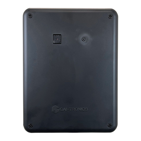
Hubbell GAI-TRONICS TempSense TS100 User manual

Pub. 42004-565B
G A I - T RO N I C S®
A H UB B E L L C O M P A N Y
TempSense Model TS100
TA B L E O F CO N T E N T S
GAI-TRONICS 3030 KUTZTOWN RD. READING, PA 19605 USA
610-777-1374 ◼800-492-1212 ◼Fax: 610-796-5954
VISIT WWW.GAI-TRONICS.COM FOR PRODUCT LITERATURE AND MANUALS
Confidentiality Notice.....................................................................................................................1
General Information.......................................................................................................................1
Installation ......................................................................................................................................2
Camera Location.....................................................................................................................................2
Wall Mount...........................................................................................................................................3
Pole Mount............................................................................................................................................3
VESA Mount ........................................................................................................................................3
Stand Mount..........................................................................................................................................3
Connections .............................................................................................................................................4
HDMI Monitor......................................................................................................................................4
USB Mouse...........................................................................................................................................4
Power....................................................................................................................................................4
Operation.........................................................................................................................................4
Environment............................................................................................................................................4
Subject Preparation................................................................................................................................5
Calibration...............................................................................................................................................5
Scan Subjects...........................................................................................................................................6
Specifications ..................................................................................................................................6
Electrical..................................................................................................................................................6
Mechanical...............................................................................................................................................6
FLIR Camera..........................................................................................................................................6
Environmental.........................................................................................................................................6

Pub. 42004-565B
GAI-TRONICS®
A HUBBELL COMPANY
TempSense Model TS100
GAI-TRONICS 3030 KUTZTOWN RD. READING, PA 19605 USA
610-777-1374 800-492-1212 Fax: 610-796-5954
VISIT WWW.GAI-TRONICS.COM FOR PRODUCT LITERATURE AND MANUALS
Confidentiality Notice
This installation and operation manual contains sensitive business and technical information that is
confidential and proprietary to GAI-Tronics. GAI-Tronics retains all intellectual property and other rights
in or to the information contained herein, and such information may only be used in connection with the
operation of your GAI-Tronics product or system. This manual may not be disclosed in any form, in
whole or in part, directly or indirectly, to any third party.
General Information
The TempSense Model TS100 measures and captures EBT (elevated body temperature) or EST (elevated
skin temperature) of subjects moving through its field of view. The TS100 consists of one FLIR®
(forward looking infra-red) camera and one standard video camera sharing the same FOV (field of view)
in a wall, pole, or stand mountable enclosure. The TS100 captures 608 × 464 resolution images on both
cameras and displays them side by side on a 1280 × 720 resolution HDMI monitor when the highest
temperature in the FOV is above the configurable preset temperature. The TS100 also captures still
images by pressing the video-capture button.
Figure 1. TempSense Model TS100

Pub. 42004-565B
TempSense Model TS100 Page 2of 6
P:\Standard IOMs - Current Release\42004 Instr. Manuals\42004-565B.docx
03/21
Installation
NOTE:The accuracy of the TempSense TS100 requires individual subjects pass within two to six feet of
the thermal imaging camera lens. Results with different camera positions may vary. Thermal
imaging camera accuracy improves as the subject moves closer to the camera.
Camera Location
Locate the TempSense TS100 so that people in a queue individually pass through the two cameras’ shared
FOV (field of view) while facing the cameras. Each subject scanned should come within two to six feet
of the cameras. The ideal height for camera installation is 5 feet 5 inches above the floor. Installation at a
higher location requires aiming the TS100 downward so that each subject’s forehead passes through the
center of the FOV (see Figure 2 and Figure 3).
Figure 2. SAMPLE FIGURE Camera Positioning (Side View)
Figure 3. SAMPLE FIGURE Camera Positioning (Top View)

Pub. 42004-565B
TempSense Model TS100 Page 3 of 6
P:\Standard IOMs - Current Release\42004 Instr. Manuals\42004-565B.docx
03/21
Wall Mount
Mount the TempSense TS100 to a wall as
follows (see Figure 5):
1. Secure the mounting plate (see Figure
4) to a flat surface using (customer
supplied) hardware.
Use the four VESA mount holes to
secure the mounting plate to the wall.
No. 8 screws fit through the 0.190-inch
threaded VESA mounting holes.
2. Secure the TS100 to the mounting
plate using the four included #6-32
screws.
Pole Mount
Mount the TempSense TS100 to a pole
(see Figure 6) as follows:
1. Secure the TS100 mounting plate (see
Figure 4) to a pole using (customer
supplied) worm-drive clamps
2. Secure the TS100 to the mounting
plate using the four included #6-32
screws.
VESA Mount
Attach a VESA (video electronics
standards association) mount to the
mounting plate with the included #10-24
screws and washers (see Figure 4).
NOTE: The TS100 includes four #10-24 ×
0.38-inch long screws to attach a
customer supplied VESA mount.
Do not use any screws other than
the included #10-24 screws to
attach the VESA mount to the
TS100’s mounting plate.
Stand Mount
Mount the TS100 to a tripod or
microphone stand using the included L-
bracket (see Figure 7).
1. Secure the mounting plate to the
TS100 using four #6-32 screws.
Figure 4. Mounting Plate Detail
Figure 5. Wall-Mount Detail
Figure 6. Pole-Mount Detail

Pub. 42004-565B
TempSense Model TS100 Page 4 of 6
P:\Standard IOMs - Current Release\42004 Instr. Manuals\42004-565B.docx
03/21
2. Secure the L-bracket to the mounting
plate using the two included #8-32 flat
head machine screws (see Figure 8).
3. Secure the L-bracket to a microphone
stand or tripod (see Figure 7).
Connections
HDMI Monitor
Plug the HDMI cable from a (customer
supplied) HDMI monitor into the HDMI
pigtail connector, on the left bottom side of
the TS100.
USB Mouse
Plug a (customer supplied) USB mouse into
the USB port pigtail, on the right bottom
side of the TS100.
Power
Plug the included power supply into the
power cord pigtail, on the left bottom side
of the TS100.
Operation
1. Power on the attached HDMI monitor.
2. Plug the TS100 power supply into a 120 V ac power outlet.
The TS100's IR sensor has a white LED that blinks slowly for 40 seconds, then changes to a fast
blink.
NOTE: If the IR sensor LED does not flash, press the sensor into its socket using a soft cloth, then
reboot the device.
3. Allow the TS100 to come up to normal operating temperature before calibration (see the Calibration
section) or operation (see the Scan Subjects section) (about 10–30 minutes).
Environment
Environmental considerations for the TS100 NCIT (non-contact infra-red thermometer) performance:
• Use the temperature scanning feature of the TS100 in a draft-free space that is out of direct sunlight
and away from radiant heat sources.
• The optimal environment for the TS100 temperature sensor is between 60.8–104 ºF (16–40 ºC) with
the relative humidity below 85 percent.
• Allow the TS100 to operate in the testing environment for 10–30 minutes to adjust to its environment
before scanning personnel.
Figure 7. TS100 L-Bracket
Figure 8. L-Bracket Attachment for Tripod/Microphone
Stand Mounting

Pub. 42004-565B
TempSense Model TS100 Page 5of 6
P:\Standard IOMs - Current Release\42004 Instr. Manuals\42004-565B.docx
03/21
Subject Preparation
To obtain accurate skin temperatures, ensure that the subject has not:
•been wearing a hat, scarf, heavy clothing, etc.
•underwent recent physical exertion
•just entered from a much lower temperature environment
•recently used facial cleaning products
•engaged in any other act that may affect their skin temperature.
Calibration
1. Place an object of known temperature in the field of view of the TS100 at the same height and
distance from where the TS100 will scan subjects.
The calibration object must be the hottest object in the FOV.
2. While watching the temperature of the object in the IR video feed (left side), press the setup button.
3. Slide the OFFSET slider to adjust the on-screen temperature until it displays the known temperature
(see Figure 9).
Figure 9. Temperature Superposition and Calibration
4. Select FAHRENHEIT or CELSIUS from the UNITS field on screen.
Selection of either scale reboots the TS100. The TS100 displays the temperature in the selected units
after rebooting.
5. Adjust the TEMP THRESHOLD to the temperature for the TS100 to alert the operator and capture a
still photo.
The TS100 captures both an IR and normal picture when the temperature exceeds the TEMP
THRESHOLD value.

Pub. 42004-565B
TempSense Model TS100 Page 6of 6
P:\Standard IOMs - Current Release\42004 Instr. Manuals\42004-565B.docx
03/21
Scan Subjects
NOTE:Accuracy of the thermal imaging camera improves as the subject moves closer to the camera.
•The monitor displays live video for the thermal imaging camera under normal operation.
•The TS100 superimposes the temperature of the hottest item in the FOV in the IR view (see Figure 9).
•When a subject with a temperature exceeding the configured temperature enters the IR camera's FOV:
•The TS100 captures and displays a still image of the IR and standard camera's picture.
•OVER TEMPERATURE flashes on screen, notifying the operator of the overtemperature subject.
•The TS100 displays the measured temperature of the subject, superimposed over the IR picture
(see note above).
1. Press the ACK/RESET button to resume normal temperature scanning.
2. Press the VIDEO CAPTURE button at any time to capture still pictures from the IR and visible light
cameras. Press the ACK/RESET button to resume temperature scanning.
Specifications
Electrical
Power.........................................................................................................................................3 A at 5 V dc
Mechanical
Dimensions .............................................................7.26 H × 5.76 W × 1.5 D in (184.4 × 146.3 × 38.1 mm)
Weight...................................................................................................................................... 2.0 lb (0.9 kg)
FLIR Camera
Horizontal FOV .........................................................................................................................................51°
Vertical FOV.........................................................................................................................................38.25°
Environmental
Operating temperature range......................................................................... 32 °F to 122 °F (0 °C to 50 °C)
Table of contents
Other Hubbell Temperature Controllers manuals
Popular Temperature Controllers manuals by other brands

Control Products
Control Products TC-110 Series quick start guide

RKC INSTRUMENT
RKC INSTRUMENT REX-P48 Series Operation manual

Emerson
Emerson Dixell XW30L - CL01 Installing and operating instructions

KIOUR
KIOUR TOUCH RSD3 quick start guide

Orton
Orton Sentry Xpress 4.0 manual

Ranco
Ranco ETC-111000 quick start guide

Athena
Athena IMP manual

MULTISPAN
MULTISPAN UTC-222 operating manual

Chromalox
Chromalox 1020 Installation & operation manual

S+S Regeltechnik
S+S Regeltechnik THERMASREG Frija I Series Operating Instructions, Mounting & Installation

PMA
PMA KS 50-1 quick start guide

Ametek Land
Ametek Land VIRALERT 3 LITE quick start guide