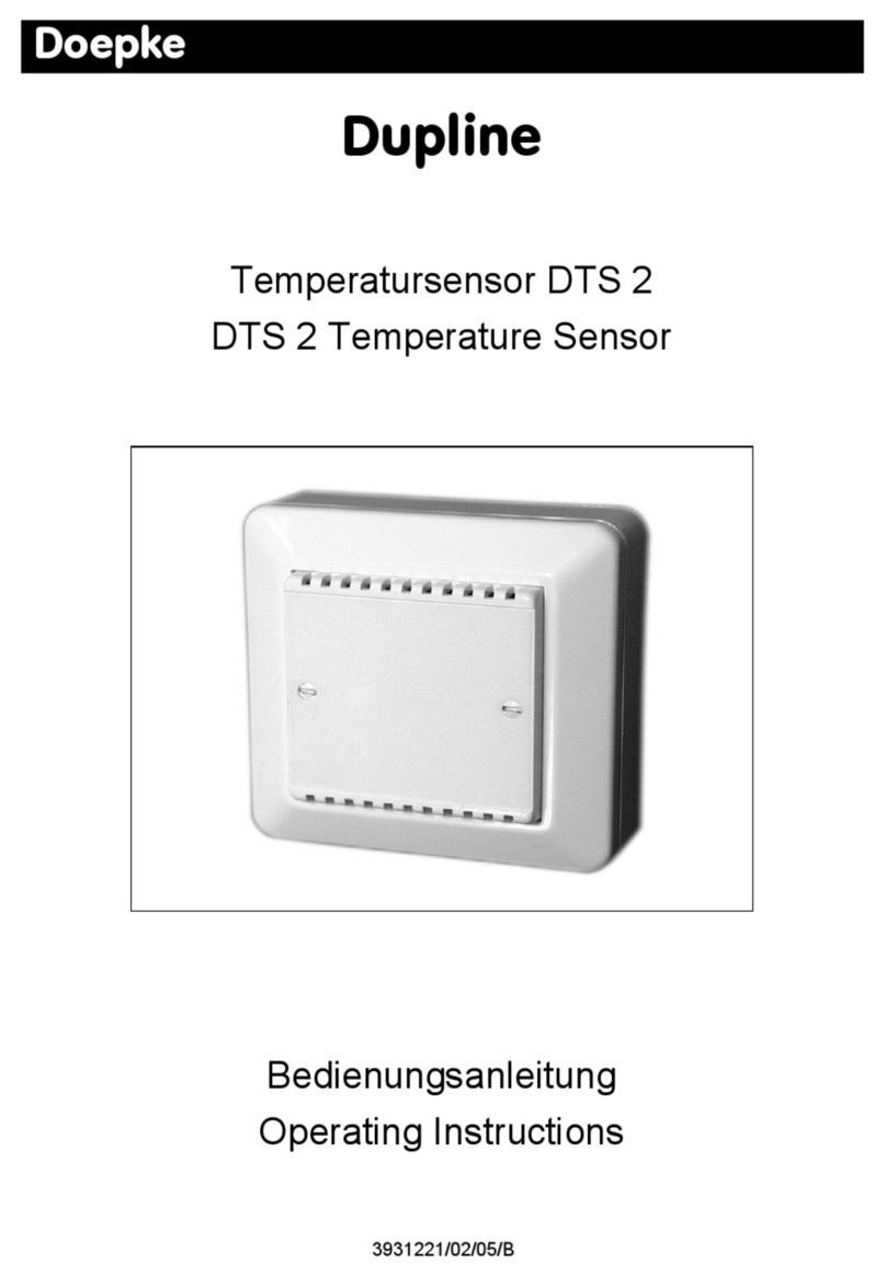
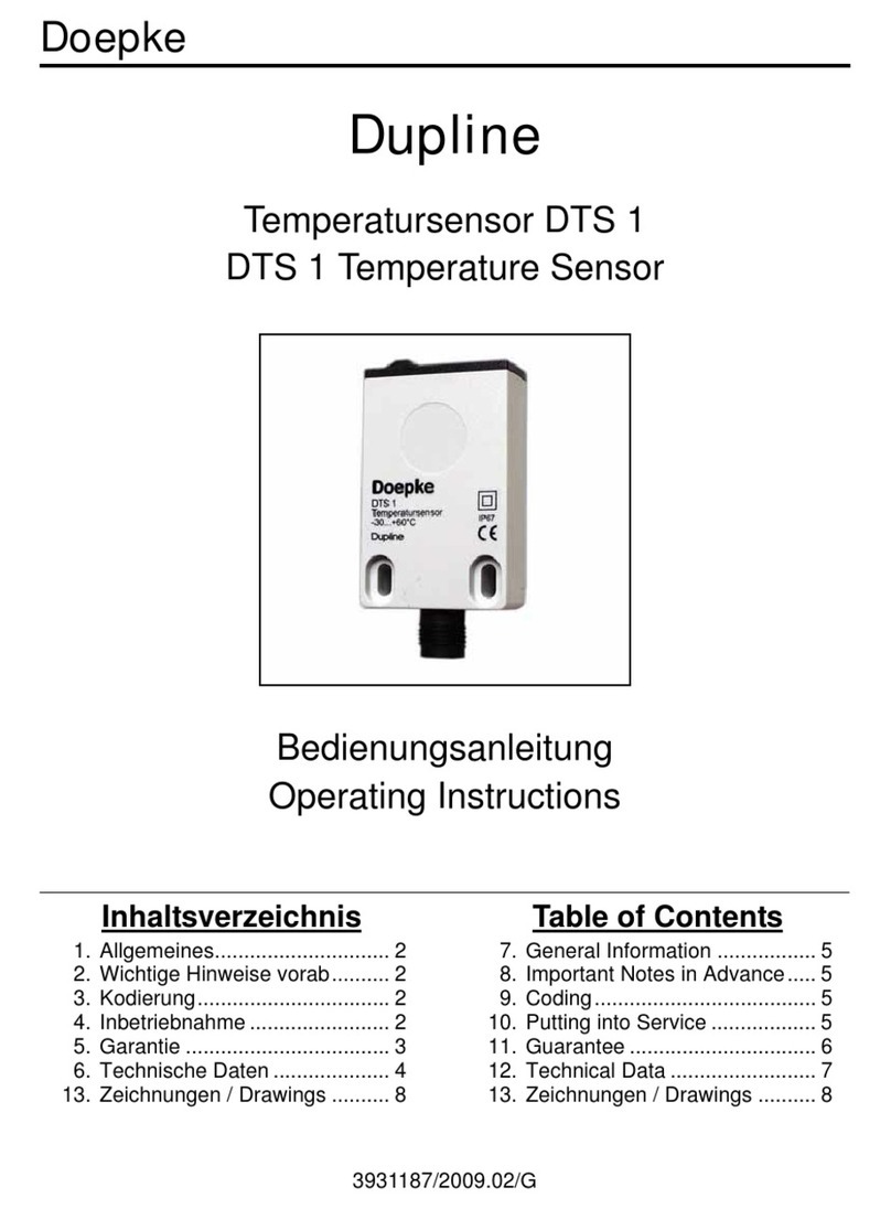
Doepke Dupline DTS 1 User manual

3931187/03/05/E
Doepke
Dupline
Temperatursensor DTS 1
DTS 1 Temperature Sensor
Bedienungsanleitung
Operating Instructions
Inhaltsverzeichnis
1. Allgemeines.............................. 2
2. Kodierung ................................. 2
3. Inbetriebnahme ........................ 2
5. Technische Daten .................... 3
4. Garantie.................................... 3
6. Anschlussschema .................... 4
Table of Contents
7. General Information.................. 5
8. Coding ...................................... 5
9. Putting into Service .................. 5
11. Technical Data ......................... 7
10. Guarantee ................................ 6
12. Connection Diagram................. 8

2 3931187/03/05/E
Doepke
Bedienungsanleitung
Dupline Temperatursensor DTS 1
1. Allgemeines
Der Temperatursensor DTS 1 ist eine Komponente des Dupline Installationssystems
und ermöglicht die Umsetzung von analogen Temperaturwerten für die Übertragung
über den Dupline-Bus.
Der DTS 1 überträgt den Temperaturwert auf einem frei kodierbaren Dupline-Kanal und
benötigt keine externe Spannungsversorgung, da er aus den Dupline-Signalleitern ver-
sorgt wird. Er ist für Anwendungen im Innen- wie auch im Aussenbereich geeignet und
lässt sich durch seine kleine Bauform unauffällig montieren.
2. Kodierung
Mit dem Handkodiergerät DHK 1 kann über den M12-Anschlussstecker an der Untersei-
te des DTS 1 dem Analogwertkanal jede beliebige Adresse zwischen A1 und P8 zuge-
ordnet werden. Die Verbindung zwischen dem DHK 1 und dem DTS 1 erfolgt durch das
M12-Kodierkabel DKP 3. Die Aufteilung der Kanäle ist wie folgt:
Funktionen, die nicht benötigt werden, sollten unkodiert bleiben. Die Kodierung des
DTS 1 kann ohne Versorgungsspannung sowie ohne Dupline-Signal vorgenommen
werden. Sie bleibt dauerhaft erhalten, kann aber jederzeit überschrieben werden.
3. Inbetriebnahme
Die Installation darf nur von einer autorisierten Fachkraft vorgenommen werden. Der
DTS 1 eignet sich zur direkten Montage an Wänden oder anderen Gegenständen. Um
einen korrekten Messwert zu erhalten, muss der DTS 1 dem Luftzug direkt ausgesetzt
sein. Daher ist eine Montage in UP-Dosen nicht empfohlen
Beim Anschluss ist die Belegung des genutzten M12-Kabels zu beachten. Werden M12-
Anschlusskabel mit mehrern Leitern verwendet, sollten die nicht benötigten Leiter mit
dem Dupline Signalleiter (Dupline -) belegt werden.
Alle anzuschließenden Leitungen müssen spannungsfrei sein. Verbindungen zwischen
dem Dupline-Signal und dem Erdpotenzial führen zu Störungen und sind nicht zulässig.
Auf die richtige Polarität des Dupline-Signals ist zu achten.
Folgende Tabelle zeigt die Anschlussbelegung:
Kanal Beschreibung Kanal Beschreibung
1 Temperaturwert 5 Nicht belegt
2 Nicht belegt 6 Nicht belegt
3 Nicht belegt 7 Nicht belegt
4 Nicht belegt 8 Nicht belegt
Klemme Beschreibung Klemme Beschreibung
1 Dupline Signalleiter + (Dupline+) 2 Dupline Signalleiter - (Dupline-)

3931187/03/05/E 3
Doepke
Die Belegung von zweiadrigen M12-Kabeln sieht folgendermaßen aus:
Dreiadrige M12-Kabel, wie zum Beispiel das DKM 1, haben folgende Anschlüsse:
Bei vieradrigen Kabeln sieht die Belegung wie folgt aus:
Um den Forderungen für Schutzkleinspannung zu genügen, ist bei der Installation die
VDE 0100, Teil 410 zu beachten und anzuwenden.
4. Garantie
Für fachgerecht montierte, unveränderte Geräte gewähren wir ab Kauf durch den End-
verbraucher die gesetzliche Gewährleistungsfrist. Die Garantie bezieht sich nicht auf
Transportschäden sowie Schäden, die durch Kurzschluss oder Überlastung entstanden
sind. Bei Fertigungs- und Materialfehlern, die innerhalb der Gewährleistungsfrist erkannt
werden, leistet unser Werk kostenlosen Ersatz. Bei Öffnen des Gerätes erlischt der Ga-
rantieanspruch.
5. Technische Daten
Draht Beschreibung Draht Beschreibung
Braun Dupline Signalleiter + (Dupline+) Blau Dupline Signalleiter - (Dupline-)
Draht Beschreibung Draht Beschreibung
Braun Dupline Signalleiter + (Dupline+) Blau Dupline Signalleiter - (Dupline-)
Schwarz Dupline Signalleiter - (Dupline-)
Draht Beschreibung Draht Beschreibung
Braun Dupline Signalleiter + (Dupline+) Blau Dupline Signalleiter - (Dupline-)
Schwarz Dupline Signalleiter - (Dupline-) Weiss Dupline Signalleiter - (Dupline-)
Min. Typ. Max.
Dupline
Stromaufnahme 800 µA
Eingangskanäle 1 Temperaturwerteingang, AnaLink-Übertragung
Ausgangskanäle Keine
Temperatursensor
Art PT1000
Messbereich -30°C +60°C
Zeitkonstante typ. 450 s (Luftströmung = 0 m/s)
typ. 350 s (Luftströmung = 1m/s)
Auflösung 8 Bit (ca. 0,35°C/Bit)
Messfehler +2%
Betriebsspannung
Nennbetriebsspannung nicht erforderlich (aus Dupline-Signalleiter)
Anschlüsse
Art M12-Anschlussstecker

4 3931187/03/05/E
Doepke
6. Anschlussschema
Gehäuse
Art Flat-Pack
Maße 35 x 68 x 15 (B x H x T in mm)
Material Polycarbonat, hellgrau
Allg. technische Daten
Betriebstemperatur -30°C +60°C
Schutzart / Normen IP67
Bestellnummer, -bezeichnung 09 501 112, DTS 1
09 501 140, DKM 1 (M12-Kabel, 2 m, gerade)
09 501 141, DKP 3 (Kodierkabel für DHK 1)
Min. Typ. Max.
M12 x 1 Stecker
M12 x 1 Stecker

3931187/03/05/E 5
Doepke
Operating Instructions
Dupline DTS 1 Temperature Sensor
7. General Information
The DTS 1 temperature sensor is a component of the Dupline installation system and al-
lows the conversion of analog temperature values for transmission on the Dupline bus.
The DTS 1 transmits the temperature data on one free encodable Dupline channel and
does not need an external power supply since this is provided by the Dupline bus.
The DTS 1 is suitable for indoor and outdoor usage and allows unobtrusive installation
due to it’s dimensions.
8. Coding
With the DHK 1 hand encoder the analog data channel can be assigned any address be-
tween A1 and P8 via the M12-plug connector. The connection between the DHK 1 and
the DTS 1 is using the optional M12 encoding cable DKP 3. The allocation of the channel
is as follows:
Functions which are not required should remain uncoded. Encoding the DTS 1 requires
neither a power supply nor the Dupline signal. Although the coding is permanently re-
tained, it may always be overwritten.
9. Putting into Service
Installation may only be carried out by an authorized technician. The DTS 1 is suitable for
direct installation at walls or other objects. The DTS 1 has to be exposed directly to the
air flow to get a proper measuring value. Therefore, an installation in switch socket boxes
is not recommended.
Observe the connections of the M12 cable used when installing. If M12 connection ca-
bles with multiple wires are used, all unused wires must be connected with the Dupline
signal conductor (Dupline -).
All leads to be connected must be dead. Connections between the Dupline signal and
earth potential will cause malfunctions and are not permissible. In addition, check for the
correct polarity of the Dupline signal.
The following table illustrates the connection configuration:
The assignment of a 2-wire M12 cable looks as follows:
Channel Description Channel Description
1 Temperature data 5 Not assigned
2 Not assigned 6 Not assigned
3 Not assigned 7 Not assigned
4 Not assigned 8 Not assigned
Pin Description Pin Description
1 Dupline signal cond.+ (Dupline+) 2 Dupline signal cond. - (Dupline-)
Wire Description Wire Description
Brown Dupline signal cond.+ (Dupline+) Blue Dupline signal cond. - (Dupline-)

6 3931187/03/05/E
Doepke
3-wire M12 cable, such as for example the DKM 1, have following assignments:
The assignment of a 4-wire M12 cable looks as follows:
In order to meet the requirements for protective low voltage, VDE 0100, Part 410, should
be observed and put into practice during installation.
10. Guarantee
All professionally installed, unaltered devices are covered by warranty during the statu-
tory guarantee period from the day of purchase by the end user. The guarantee is not ap-
plicable to damage incurred during transport or caused by short-circuit or overloading. In
the event of defects in workmanship or material, which are discovered within the guar-
antee period, the company will provide a replacement free of charge. The guarantee will
be rendered null and void if the device is opened or tampered with.
Wire Description Wire Description
Brown Dupline signal cond.+ (Dupline+) Blue Dupline signal cond. - (Dupline-)
Black Dupline signal cond. - (Dupline-)
Wire Description Wire Description
Brown Dupline signal cond.+ (Dupline+) Blue Dupline signal cond. - (Dupline-)
Black Dupline signal cond. - (Dupline-) White Dupline signal cond. - (Dupline-)

3931187/03/05/E 7
Doepke
11. Technical Data
Min. Typ. Max.
Dupline
Current input 800 µA
Input channels 1 Temperature value
Output channels None
Temperature sensor
Type PT1000
Measuring range -30°C +60°C
Time constant typ. 450 s (air flow = 0 m/s)
typ. 350 s (air flow = 1m/s)
Resolution 8 Bit (approx. 0.35°C/Bit)
Measuring error +2%
Operating Voltage
Rated operating voltage Not required (supplied by Dupline signal line)
Terminals
Type M12-socket connection
Housing
Type Flat-pack design
Dimensions 35 x 68 x 15 (W x H x D in mm)
Material Polycarbonate, light gray
General technical data
Ambient temperature -30°C +60°C
Encl. protection type /
standards IP67
Order number, description 09 501 112, DTS 1
09 501 140, DKM 1 (M12-cable, 2 m, straight)
09 501 141, DKP 3 (Coding cable for DHK 1)

8 3931187/03/05/E
Doepke
12. Connection Diagram
Sollten Sie Fragen zu diesem Produkt
oder zum Dupline-System haben, wen-
den Sie sich bitte an:
In case of queries concerning this
product or the Dupline system plea-
se contact:
Doepke
Schaltgeräte GmbH & Co. KG
Stellmacherstraße 11
D-26506 Norden, Germany
Tel.: +49 (0) 4931/1806-0
Fax: +49 (0) 4931/1806-101
E-mail:
Internet:
http://www.doepke.de
3931187/03/05/E
M12 x 1 plug
M12 x 1 plug
This manual suits for next models
1
Table of contents
Languages:
Other Doepke Temperature Controllers manuals
Popular Temperature Controllers manuals by other brands

Full Gauge
Full Gauge TO-712B quick start guide

Newport
Newport 3150 user manual

Dwyer Instruments
Dwyer Instruments 16A2 Series instructions

TE Technology
TE Technology TC-48-20 instruction manual

Autonics
Autonics TK Series User Manual for Communication

Siemens
Siemens Landis & Staefa REV11 Series operating instructions

RKC INSTRUMENT
RKC INSTRUMENT REX-P48 Series Operation manual

Oregon Scientific
Oregon Scientific THGN132N user manual

AERMEC
AERMEC NRL0280E Installation and maintenance manual

Julabo
Julabo LC4 F operating manual

Store It Cold
Store It Cold CoolBot Quick start setup guide

Ropex
Ropex CIRUS UPT-6010 operating instructions