Linkoln Electric EASYTOME 1020 Mounting instructions

CUTTING MACHINE
EASYTOME
1020-1515-1530-2040
MACHINE N°
W000379055 - W000379056 - W000379057 - W000379058 -
W000379059 - W000379060 - W000379061 - W000379062
SAFETY INSTRUCTIONS FOR USE AND MAINTENANCE
EASYTOME ESSENTIAL
1530
MACHINE N°
W000400274 - W000400273
SAFETY INSTRUCTIONS FOR USE AND MAINTENANCE
EDITION : EN Instructions for use REF : 8695 4387
REVISION : H
DATE : 10-2018 Original instructions

Thank for the trust you have expressed by purchasing this equipment, which
will give you full satisfaction if you follow its instructions for use and
maintenance.
Its design, component specifications and workmanship comply with
applicable European directives.
Please refer to the enclosed CE declaration to identify the directives
applicable to it.
The manufacturer will not be held responsible where items not recommended
by themselves are associated with this product.
For your safety,there follows a non-restrictive list of recommendations or
requirements, many of which appear in the employment code.
Finally we would ask you kindly to inform your supplier of any error which
you may find in this instruction manual.

8695 4387
EASYTOME I
CONTENTS
A - IDENTIFICATION .........................................................................................................................1
B - SAFETY RULES...........................................................................................................................2
1 - AIRBORNE NOISE .............................................................................................................2
2 - SPECIAL SAFETY RULES.................................................................................................4
C - DESCRIPTION .............................................................................................................................5
1 - MECHANICAL ASSEMBLY................................................................................................5
2 - CUTTING TABLE................................................................................................................6
3 - POWER SYSTEMS ............................................................................................................6
4 - CONSOLE...........................................................................................................................6
5 - PLASMA SYSTEM..............................................................................................................7
6 - LIMIT OF SUPPLY..............................................................................................................7
7 - OPTIONAL..........................................................................................................................7
D - ASSEMBLY AND INSTALLATION..............................................................................................8
1 - CONDITIONS OF INSTALLATION.....................................................................................8
2 - ARRANGEMENT OF CABLES AND HOSES.....................................................................8
3 - PREPARING THE FLOOR .................................................................................................9
4 - PUTTING THE MACHINE IN PLACE.................................................................................10
5 - PLACING THE MACHINE...................................................................................................11
6 - ELECTRICAL AND FLUIDIC CONNECTION.....................................................................11
7 - REMOVAL AND DISASSEMBLY........................................................................................13
E - OPERATOR MANUAL.................................................................................................................14
1 - DESCRIPTION OF CONTROLS VERSION EASYTOME ...................................................14
2 - DESCRIPTION OF CONTROLS VERSION EASYTOME ESSENTIAL...............................15
3 - STARTING UP....................................................................................................................16
4 - STOPPING THE MACHINE................................................................................................16
5 - USING THE MACHINE.......................................................................................................17
F - USE OF THE PLASMA SYSTEM.................................................................................................18
1 - CUTTING TO A PROGRAM: SIMPLIFIED PROCEDURE.................................................18
2 - USE OF NERTAJET 40i ......................................................................................................22
3 - CONSUMABLES FOR TORCH OCP100 ...........................................................................23
4 - CUTTING PARAMETERS ..................................................................................................24
5 - USE OF FLEXCUT 125 CE LC125M ..................................................................................24
6 - CONSUMABLES FOR TORCH LC125M ...........................................................................24
7 -USEFUL INFORMATION FOR ADJUSTING THE PARAMETERS ..................................25
8 - RECOMMENDATIONS FOR START AND END PORTIONS............................................27
G - MAINTENANCE...........................................................................................................................29
1 - SERVICING.........................................................................................................................29
2 - SPARE PARTS EASYTOME...............................................................................................31
3 - SPARE PARTS EASYTOME ESSENTIAL...........................................................................33
4 - BLOCK DIAGRAM ..............................................................................................................34
5 - PNEUMATIC DIAGRAM .....................................................................................................35
PERSONAL NOTES ..........................................................................................................................36

8695 4387
II EASYTOME
INFORMATIONS
DISPLAYS AND PRESSURE GAUGES
The measuring devices or displays for voltage, current, speed, pressure, etc., whether analog or digital, should be
considered as indicators.
REVISIONS
REVISION H 10/18
DESIGNATION
PAGE
Created in English

8695 4387 / H
EASYTOME A-1
A - IDENTIFICATION
Please report the registration number of your appliance in the table here below.
Please provide this information whenever you contact us.
1
Machine type
EASYTOME
2
year of manufacture
20xx
3
Serial number of the product
AFxxxxxxx
1
2
3

8695 4387 / H
B-2 EASYTOME
B - SAFETY RULES
General information: please refer to the document about the "SAFETY RULES" ref. 8695-7050
1 - AIRBORNE NOISE
1 - CERTIFICATION OF THE MEASURING SITE
The machine has been tested in the workshop in Pont Sainte Maxence:
5 place Chatelier
60700 PONT SAINTE MAXENCE
FRANCE
Qualification has been recorded in a report
n°17563386/1
2 - SOUND PRESSURE MEASUREMENT
The values are stated in weighted equivalent sound level (LAeq)
The measuring unit is dB (A): A-weighted decibel
The measurements were made 1.6 m away from the ground with a FUSION sound level meter, no 10925,
inspected by an approved laboratory (LNE).
3 - MEASUREMENTS (see next page)

8695 4387 / HB - SAFETY RULES
EASYTOME B-3
Refer to the special instructions supplied with the equipment.
FLEXCUT125CE
Measuring conditions
M1
M2
Intensity
85 A
125 A
Material
Carbon steel 8mm
Carbon steel 20mm
Gas
Compressed air
Compressed air
Leq. = Equivalent A-weighted acoustic pressure level
Lpc. = Peak acoustic pressure level

B - SAFETY RULES 8695 4387 / H
B-4 EASYTOME
2 - SPECIAL SAFETY RULES
MAINTENANCE CONDITIONS, CONDITIONS OF USE
No object is to be placed on the rolling tracks
For installation or maintenance operations, the operator must use the lifting eyes provided for that
purpose and shown on the drawing (see Handling section).
STABILITY
Do not climb on the cable drag chain.
Before handling plates, make sure that the safety of persons and property is protected.
The machine must be anchored to the floor (see layout paragraph).
Before using the machine, make sure that all the guards are in place.
No maintenance may be carried out on the machine when it is supplied with power.
Switch off the power source while changing the wearing parts of the torch if the plasma process is
being used.
CONDUCTING MAINTENANCE ON PIECES
The equipment for handling workpieces that have been or need to be cut is not part of the supply
and is to be provided by the customer. The customer must therefore take protective measures
appropriate for the equipment for handling the workpieces
CAUTION: While handling the metal plates to cut, take the necessary
precautions to avoid impacts on the machine and the rolling tracks.
Impacts on these elements could lead to squareness faults and
therefore unsatisfactory cutting.

8695 4387 / H
EASYTOME C-5
C - DESCRIPTION
Numerically controlled monobloc plasma cutting
machine that is particularly suited to industries that
use steel, stainless steel and aluminium.
The main intended applications are those of iron
workers, metal workers, air processing, air-
conditioning, ventilation, refractory industries,
workshops producing in small and medium runs or
support production.
The machine will be equipped with:
A plasma system with a NERTAJET 40i OCP
100 or FLEXCUT125 CE torch capable of cutting
steel, stainless steel and aluminium with air
NB: another plasma system may be used
providing it does not operate with HF.
Optional :
Possibility to add :
a pipe-cutting mandrel,
a micro-vibrations engraving marker
others on request
The NC system with the GALAAD drawing/tool
path software may also be connected to a
programming centre.
It is integrated into the control console.
Its compact dimensions make it easy to carry and
quick to install.
The extraction table incorporated into the machine
may be connected to any extraction and/or filtration
system.
1 - MECHANICAL ASSEMBLY
This is a monobloc machine that is made up of a
very rigid mechanically welded frame that is placed on
the floor on several feet.
The cross carriage is fitted on the beam. It is guided
by two slide rails and driven by a brushless(*) geared
motor and rack assembly.
The numerical tool holder has a 100 mm travel
range and is fitted with a step motor, with plate sensing
mounted on the carriage.
Two longitudinal guide assemblies are fitted to the
frame, each with a slide rail and reverse rack. Racks
are fitted to the rails to move the beam.
The high-speed feed speed of EASYTOME is :
- Step motor version : 20 m/min,
- Step motor version : 21 m/mn
The electrical control cabinet contains all the
electrical and electronic equipment for controlling the
machine and a turning numerical control console to
allow the operator to control the machine.

C - DESCRIPTION 8695 4387 / H
C-6 EASYTOME
2 - CUTTING TABLE
This is a mechanically welded box fastened to the
floor between the machine frame, with an outlet for
connection to an extraction system.
Depending on the machine model, the table may be
divided into several sections.
For this table, we recommend the use of extraction
with filtration that is suited to machine performance.
Thanks to its 750 mm height and rails incorporated
very close to the table, loading and unloading of parts
and plates is very easy.
One or more removable supporting frames are
placed on the box.
They have easily replaceable plate support irons.
On EASYTOME 1515/1530/2040, grating with a
50x50 mm(*) mesh hold the cut parts in the event of
scrap. They are replaceable.
Several slag boxes are provided at the back of the
table and are removable for cleaning.
3 - POWER SYSTEMS
The machine has a digital power system, using either step technology as regards EASYTOME Essential or
brushless technology as regards EASYTOME 1020/1515/1530/2040.
4 - CONSOLE
Version EASYTOME
Version EASYTOME Essential
The control console includes:
A touch screen in EASYTOME and a standard screen in EASYTOME Essential
One or more emergency stops
All the controls required for starting up
The drawing and tool path software for nesting simple parts or importing programs in the form of ISO
codes from nesting software such as MAGICNEST 01 or 10 installed on an outside station.
A manual machine movement interface
A plasma cycle control interface including a parameter database.

8695 4387 / HC - DESCRIPTION
EASYTOME C-7
5 - PLASMA SYSTEM
The machine has a NERTAJET 40i plasma cutting system with an OCP100 plasma torch or a FLEXCUT125CE
with an LC125M plasma torch
That system mainly allows cutting steel, stainless steel and aluminium.
Cutting capacity:
N40i OCP100 : 12 mm production piercing, 20 mm maximum piercing, 40 mm start at the end of a
plate
FLEXCUT125CE LC125M : 25 mm production piercing, 30 mm maximum piercing, 45 mm start at
the end of a plate
Another type of plasma system may be incorporated providing it operates without high frequency.
Please refer to the safety, operating and maintenance instructions of each component, namely:
Power source: 8695 1169: NERTAJET 40i (PRESTOJET 4C)
Torch: 8695 1205: OCP100
Power source: IM10375 : FLEXCUT125CE
6 - LIMIT OF SUPPLY
The customer must supply and install a device on each source for
isolating it. The devices must be clearly identified. They must be
lockable in accordance with standard EN 60204-1.
Lincoln Electric offers the following additional items with the machine :
Table air pipe
W000010073
ARG.WLD.HOSE D10x16 40M
W000290896
BAG 10 COLLAR D10
Table/customer earth equipotential bonding cable
W000260272
WELDING CABLE H01N2D 16MM 2
W000010094
Screw lug, diam 11mm - 0-25mm2
7 - OPTIONAL
Refer to the enclosed instructions of the corresponding option :
Optional extraction fan.
Optional extraction filter : ESSENTIAL 2CD, 4CD or 6CD depending on the machine model.
Optional disconnecting elements: electrical cabinet

8695 4387 / H
D-8 EASYTOME
D - ASSEMBLY AND INSTALLATION
1 - CONDITIONS OF INSTALLATION
THE LAYOUT OF THE INSTALLATION MUST COMPLY WITH SAFETY STANDARD NF EN 547 -
1 -3 TO ENSURE PERSONAL PROTECTION
THE FOLLOWING CONDITIONS MUST BE COMPLIED
WITH BEFORE INSTALLING THE EQUIPMENT
ELECTRICITY SUPPLY
VERY IMPORTANT
For compliance with European safety standards, the connection to the electricity supply is to be
made via a wall-mounted cabinet with an individual protective sectioning switch with rating
appropriate for the mains voltage and the consumption by the devices.
The protective disconnector must offer breaking capacity of 100KA
We market cabinets that meet these criteria.
POWER CONSUMPTION
EASYTOME and EASYTOME Essential
230V 5A
NERTAJET 40i- OCP 100
400V 25.2A
FLEXCUT 125 CE - LC125M
400V 40A
PNEUMATIC SUPPLY
Provide a source of compressed air with a regulator that can supply the required flow
and pressure. The air must be clean, de-oiled and degreased.
Supply pressure values
of the system
Max. flow rate used
in m3/h
Extraction table
5 bar +/- 0,5
5
NERTAJET 40i OCP 100
7 Bar +/-0,5
13 (220 l/min)
FLEXCUT 125 CE - LC125M
6,21 to 8,27 bar
15,6 (260 l/min)
2 - ARRANGEMENT OF CABLES AND HOSES
The customer must provide the means to support and protect cables and hoses from
mechanical, chemical or thermal damage from their source up to the entrance to the cable drag
chain.

8695 4387 / HD - ASSEMBLY AND INSTALLATION
EASYTOME D-9
3 - PREPARING THE FLOOR
The installation of EASYTOME does not require any particular preparation of the floor.
However, we recommend clean concrete, so as to ensure that the machine is stable.
The machine location must follow the standard layout recommendations of the machine,
as given in drawing W000379245. Here is an excerpt:
D - ASSEMBLY AND INSTALLATION 8695 4387 / H
D-10 EASYTOME
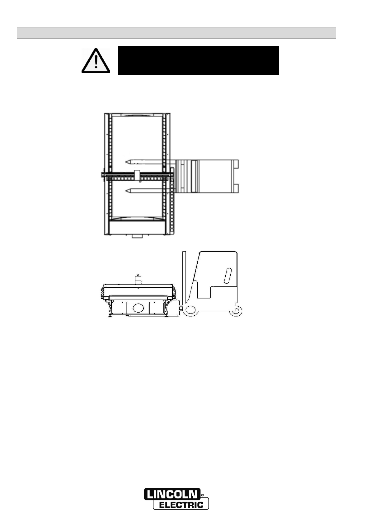
4 - PUTTING THE MACHINE IN PLACE
Operator protection:
Helmet - Gloves - Safety shoes
The machine and the cutting table are
transported simultaneously
The components of the system may only be transported
using the lifting points provided, with appropriate equipment
Machine
Weight
W000379055
EASYTOME 1020 CNC LEFT
1000 Kg
W000379056
EASYTOME 1020 CNC RIGHT
1000 Kg
W000379057
EASYTOME 1515 CNC LEFT
1000 Kg
W000379058
EASYTOME 1515 CNC RIGHT
1000 Kg
W000379059
EASYTOME 1530 CNC LEFT
1700 Kg
W000379060
EASYTOME 1530 CNC RIGHT
1700 Kg
W000379061
EASYTOME 2040 CNC LEFT
2100 Kg
W000379062
EASYTOME 2040 CNC RIGHT
2100 Kg
W000400273
EASYTOME Essential 1020
1000 Kg
W000400274
EASYTOME Essential 1530
1200 Kg

8695 4387 / HD - ASSEMBLY AND INSTALLATION
EASYTOME D-11
5 - PLACING THE MACHINE
The machine must be placed in the workshop in accordance with the recommendations of the layout
drawing W000379245.
Adjust the horizontality of the machine in both planes with a level offering precision to 1/10th of a metre
using the feet.
The low inertia of the machine means that it does not have to be fastened.
However, if you do want to fasten it, the feet have holes for that purpose
6 - ELECTRICAL AND FLUIDIC CONNECTION
Electrical:
Lincoln Electric recommends using electrical connectors according to the recommendations in the layout drawing
W000379245. Excerpt:
Supply by the customer of the three power supplies + earth 5 Ohms max
Machine:
2.5 KVA 220/230V
Single-phase wall socket
Power source:
-25.2A/400V (N40i)
- 40A/400V (FLEXCUT125CE)
Three-phase wall socket
Building earth
5 Ohms max
Examples of wall sockets to use:
Three phase 400V
Single phase
230V

D - ASSEMBLY AND INSTALLATION 8695 4387 / H
D-12 EASYTOME
Equipotential bonding:
Caution! The machine requires equipotential bonding between the table and the earth of the customer’s building.
LINCOLN ELECTRIC supplies the required connection:
W000260272
WELDING CABLE H01N2D 16MM 2
W000010094
Screw lug, diam 11mm - 0-25mm2
The machine table may be made up of several modules. Make sure that an equipotential cable is connected
between the different modules.
Schematic diagram of the equipotential connection:
Pneumatic:
Lincoln Electric recommends the supply of pneumatic supplies as recommended in the layout drawing
W000379245. Excerpt:
System air
Dry and oil free air
Hose connector Ø 10
Hose connector Ø 6
Table
5m3/h
7bar ±0,5
Nertajet 40i: 13 m3/h or 220 l/min, 7bar ±1
FLEXCUT125CE, 15,6 m3/h (260 l/min), 6,21 to 8,27 bar
The valves must be lockable with venting on all feeders.
Filter and extraction connections: please refer to the corresponding instructions
Equipotential link
Equipotential cable
table modules
Plasma
_
+
Building
earth 5 ohms
max

8695 4387 / HD - ASSEMBLY AND INSTALLATION
EASYTOME D-13
Caution! For any work on the machine, you must disconnect the elements separately: machine, power source and
filter.
A warning label on the supply points of the different components and the different components that are supplied
warns of the hazard:
7 -REMOVAL AND DISASSEMBLY
Please enquire with LINCOLN ELECTRIC
Caution! The machine, the extraction system and the power
source are powered separately.
Before any work, make sure that their power supplies have
been switched off.

8695 4387 / H
E-14 EASYTOME
E - OPERATOR MANUAL
1 - DESCRIPTION OF CONTROLS VERSION EASYTOME
The disconnector on the electrical cabinet of
EASYTOME controls the power supply to the machine.
The console has:
A touchscreen
An electrical safety circuit reset switch (green)
Two emergency stop buttons
PC starting up button
Remote buttons for starting up extraction
Keyboard and tactile mouse for programming
and using the machine
USB port
USB port
Electrical safety reset
Emergency stop
PC start
Remote controls for fume
extraction:
Manual or auto mode
Manual operation
Manual stop
Emergency stop
Touch mouse keyboard for
machine programming and
use

8695 4387 / HE - OPERATOR MANUAL
EASYTOME E-15
2 - DESCRIPTION OF CONTROLS VERSION EASYTOME ESSENTIAL
The disconnector on the side of the console of
’EASYTOME Essential controls the power supply to the
machine.
The console has:
A standard screen
An electrical safety circuit reset switch (green)
One emergency stop button
PC starting up button
Remote buttons for starting up extraction
Keyboard and mouse for programming and
using the machine
USB port
On the side of the
machine console (right or
left depending on machine
layout):
Main electric
disconnector
Electrical safety
circuit reset button
USB port
Remote controls for fume
extraction:
Manual or auto mode
Manual operation
Manual stop
Emergency stop
Keyboard and mouse for
machine programming and
use

E - OPERATOR MANUAL 8695 4387 / H
E-16 EASYTOME
3 - STARTING UP
Procedure for the machine
Turn the disconnector of the electrical cabinet
Press the Start PC button
Press and hold down the green reset button
Procedure for the extraction system
NB: the remote controls must be connected to the extraction control unit (optional service from the fitter)
Select the manual or automatic mode
Manual mode: extraction starts when the manual On button is pressed
Automatic mode: extraction starts automatically at the start of the automatic cutting cycle of the program
4 - STOPPING THE MACHINE
Procedure for the machine
Use the emergency stop button
Use the On/Off button or the Windows shutdown button on the PC
When the PC has shut down, turn the disconnector of the electrical cabinet
Procedure for the extraction system
Manual mode: extraction stops when the manual Off button is pressed
Automatic mode: extraction stops automatically at the end of the automatic cutting cycle of the program
If the operator is away for an extended period of time or if any work is done on the cutting tools, the energy
supplies must absolutely by shut off
Caution! The rotary switch on electrical cabinet only isolates the gantry machine,
but not the plasma cutting process or the extraction system
This manual suits for next models
11
Table of contents


