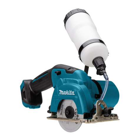
Makita DMC300 User manual

DMC300
EN Cordless Compact Cut O INSTRUCTION MANUAL 8
SL Akumulatorski kompaktni
rezalnik NAVODILA ZA UPORABO 17
SQ Prerëse kompakte me bateri MANUALI I PËRDORIMIT 26
BG Акумулаторен компактен
циркуляр РЪКОВОДСТВО ЗА
ЕКСПЛОАТАЦИЯ 35
HR Akumulatorski kompaktni
alat za rezanje PRIRUČNIK S UPUTAMA 45
МК Безжична компактна пила УПАТСТВО ЗА УПОТРЕБА 54
SR Бежични компактни алат за
одсецање УПУТСТВО ЗА УПОТРЕБУ 64
RO Mașină de debitat compactă
fără cablu MANUAL DE INSTRUCŢIUNI 74
UK Бездротова компактна
відрізна пила ІНСТРУКЦІЯ З
ЕКСПЛУАТАЦІЇ 84
RU Аккумуляторная отрезная
дисковая пила РУКОВОДСТВО ПО
ЭКСПЛУАТАЦИИ 94

2
1
2
3
Fig.1
1
2
Fig.2
1
2
Fig.3
1
Fig.4
1
2
1
2
1
Fig.5
1
2
1
1
2
Fig.6
1
2
Fig.7

3
1
2
Fig.8
1
Fig.9
1
Fig.10
1
3
2
Fig.11
1
3
2
3
Fig.12

4
1
2
3
4
Fig.13
1
Fig.14
1
2
3
4
5
Fig.15
1
2
3
4
5
Fig.16
1
2
3
Fig.17
1
Fig.18

5
12
3
4
Fig.19
1
2
Fig.20
2
1
Fig.21
1
2
3
Fig.22
1
2
3
4
5
Fig.23
1
2
Fig.24

6
1
2
Fig.25
Fig.26
Fig.27
Fig.28
Fig.29

7
12
Fig.30
1
2
Fig.31

8ENGLISH
ENGLISH (Original instructions)
SPECIFICATIONS
Model: DMC300
Wheel outer diameter 76 mm
Wheel inner (arbor) diameter 10.0 mm / 9.5 mm (3/8″) (country specic)
Max. wheel thickness 1.0 mm
Max. cutting capacities With dust collect cover 13.5 mm
Without dust collect cover 16.0 mm
Rated speed (n) / No load speed (n0)20,000 min-1
Overall length 271 mm *1
Rated voltage D.C. 18 V
Net weight 1.2 - 1.7 kg
*1. With battery cartridge (BL1860B) / Without dust collection cover
• Due to our continuing program of research and development, the specications herein are subject to change
without notice.
• Specications and battery cartridge may dier from country to country.
• The weight may dier depending on the attachment(s), including the battery cartridge. The lightest and heavi-
est combinations, according to EPTA-Procedure 01/2014, are shown in the table.
Applicable battery cartridge and charger
Battery cartridge BL1815N / BL1820B / BL1830B / BL1840B / BL1850B / BL1860B
Charger DC18RC / DC18RD / DC18RE / DC18SD / DC18SE / DC18SF /
DC18SH / DC18WC
• Some of the battery cartridges and chargers listed above may not be available depending on your region of
residence.
WARNING: Only use the battery cartridges and chargers listed above. Use of any other battery cartridges
and chargers may cause injury and/or re.
Intended use
The tool is intended for cutting a sheet, tting, pipe, tile
or wall in metal, plastic, ceramic, plaster and similar
composite materials without use of water.
Noise
The typical A-weighted noise level determined accord-
ing to EN60745-2-22:
Sound pressure level (LpA) : 88 dB (A)
Sound power level (LWA) : 99 dB (A)
Uncertainty (K) : 3 dB (A)
NOTE: The declared noise emission value(s) has
been measured in accordance with a standard test
method and may be used for comparing one tool with
another.
NOTE: The declared noise emission value(s)
may also be used in a preliminary assessment of
exposure.
WARNING: Wear ear protection.
WARNING: The noise emission during actual
use of the power tool can dier from the declared
value(s) depending on the ways in which the
tool is used especially what kind of workpiece is
processed.
WARNING: Be sure to identify safety mea-
sures to protect the operator that are based on an
estimation of exposure in the actual conditions of
use (taking account of all parts of the operating
cycle such as the times when the tool is switched
o and when it is running idle in addition to the
trigger time).
Vibration
The vibration total value (tri-axial vector sum) deter-
mined according to EN60745-2-22:
Work mode: concrete cutting (thickness 5 mm)
Vibration emission (ah) : 3.0 m/s2
Uncertainty (K) : 1.5 m/s2

9ENGLISH
NOTE: The declared vibration total value(s) has been
measured in accordance with a standard test method
and may be used for comparing one tool with another.
NOTE: The declared vibration total value(s) may also
be used in a preliminary assessment of exposure.
WARNING: The vibration emission during
actual use of the power tool can dier from the
declared value(s) depending on the ways in which
the tool is used especially what kind of workpiece
is processed.
WARNING: Be sure to identify safety mea-
sures to protect the operator that are based on an
estimation of exposure in the actual conditions of
use (taking account of all parts of the operating
cycle such as the times when the tool is switched
o and when it is running idle in addition to the
trigger time).
EC Declaration of Conformity
For European countries only
The EC declaration of conformity is included as Annex A
to this instruction manual.
SAFETY WARNINGS
General power tool safety warnings
WARNING: Read all safety warnings, instruc-
tions, illustrations and specications provided
with this power tool. Failure to follow all instructions
listed below may result in electric shock, re and/or
serious injury.
Save all warnings and instruc-
tions for future reference.
The term "power tool" in the warnings refers to your
mains-operated (corded) power tool or battery-operated
(cordless) power tool.
Compact cut o safety warnings
1. The guard provided with the tool must be
securely attached to the power tool and
positioned for maximum safety, so the least
amount of wheel is exposed towards the oper-
ator. Position yourself and bystanders away
from the plane of the rotating wheel. The guard
helps to protect operator from broken wheel frag-
ments and accidental contact with wheel.
2. Use only bonded reinforced or diamond cut-o
wheels for your power tool. Just because an
accessory can be attached to your power tool, it
does not assure safe operation.
3. The rated speed of the accessory must be at
least equal to the maximum speed marked on
the power tool. Accessories running faster than
their rated speed can break and y apart.
4.
Wheels must be used only for recommended
applications. For example: do not grind with the
side of cut-o wheel. Abrasive cut-o wheels are
intended for peripheral grinding, side forces applied
to these wheels may cause them to shatter.
5. Always use undamaged wheel anges that are
of correct diameter for your selected wheel.
Proper wheel anges support the wheel thus
reducing the possibility of wheel breakage.
6. Do not use worn down reinforced wheels from
larger power tools. Wheels intended for a larger
power tool are not suitable for the higher speed of
a smaller tool and may burst.
7. The outside diameter and the thickness of your
accessory must be within the capacity rating
of your power tool. Incorrectly sized accessories
cannot be adequately guarded or controlled.
8. The arbour size of wheels and anges must
properly t the spindle of the power tool.
Wheels and anges with arbour holes that do not
match the mounting hardware of the power tool
will run out of balance, vibrate excessively and
may cause loss of control.
9. Do not use damaged wheels. Before each
use, inspect the wheels for chips and cracks.
If power tool or wheel is dropped, inspect for
damage or install an undamaged wheel. After
inspecting and installing the wheel, position
yourself and bystanders away from the plane
of the rotating wheel and run the power tool
at maximum no load speed for one minute.
Damaged wheels will normally break apart during
this test time.
10. Wear personal protective equipment. Always
wear hearing protection. Depending on
application, use face shield, safety goggles
or safety glasses. As appropriate, wear dust
mask, gloves and shop apron capable of stop-
ping small abrasive or workpiece fragments.
The eye protection must be capable of stopping
ying debris generated by various operations.
The dust mask or respirator must be capable of
ltrating particles generated by your operation.
Prolonged exposure to high intensity noise may
cause hearing loss.
11. Keep bystanders a safe distance away from
work area. Anyone entering the work area
must wear personal protective equipment.
Fragments of workpiece or of a broken wheel may
y away and cause injury beyond immediate area
of operation.
12. Hold the power tool by insulated gripping
surfaces only, when performing an operation
where the cutting accessory may contact hid-
den wiring. Cutting accessory contacting a “live”
wire may make exposed metal parts of the power
tool “live” and could give the operator an electric
shock.
13. Never lay the power tool down until the acces-
sory has come to a complete stop. The spinning
wheel may grab the surface and pull the power
tool out of your control.
14. Do not run the power tool while carrying it at
your side. Accidental contact with the spinning
accessory could snag your clothing, pulling the
accessory into your body.

10 ENGLISH
15. Regularly clean the power tool’s air vents. The
motorʼs fan will draw the dust inside the housing
and excessive accumulation of powdered metal
may cause electrical hazards.
16. Do not operate the power tool near ammable
materials. Sparks could ignite these materials.
Kickback and related warnings
Kickback is a sudden reaction to a pinched or snagged
rotating wheel. Pinching or snagging causes rapid stall-
ing of the rotating wheel which in turn causes the uncon-
trolled power tool to be forced in the direction opposite of
the wheel’s rotation at the point of the binding.
For example, if an abrasive wheel is snagged or
pinched by the workpiece, the edge of the wheel that is
entering into the pinch point can dig into the surface of
the material causing the wheel to climb out or kick out.
The wheel may either jump toward or away from the
operator, depending on direction of the wheel’s move-
ment at the point of pinching. Abrasive wheels may also
break under these conditions.
Kickback is the result of power tool misuse and/or
incorrect operating procedures or conditions and can be
avoided by taking proper precautions as given below.
1. Maintain a rm grip on the power tool and
position your body and arm to allow you to
resist kickback forces. Always use auxiliary
handle, if provided, for maximum control over
kickback or torque reaction during start-up.
The operator can control torque reactions or kick-
back forces, if proper precautions are taken.
2. Never place your hand near the rotating acces-
sory. Accessory may kickback over your hand.
3. Do not position your body in line with the
rotating wheel. Kickback will propel the tool in
direction opposite to the wheel’s movement at the
point of snagging.
4. Use special care when working corners, sharp
edges etc. Avoid bouncing and snagging the
accessory. Corners, sharp edges or bouncing
have a tendency to snag the rotating accessory
and cause loss of control or kickback.
5. Do not attach a saw chain, woodcarving blade,
segmented diamond wheel with a peripheral
gap greater than 10 mm or toothed saw blade.
Such blades create frequent kickback and loss of
control.
6. Do not “jam” the wheel or apply excessive
pressure. Do not attempt to make an excessive
depth of cut. Overstressing the wheel increases
the loading and susceptibility to twisting or binding
of the wheel in the cut and the possibility of kick-
back or wheel breakage.
7. When wheel is binding or when interrupting
a cut for any reason, switch o the power
tool and hold the power tool motionless until
the wheel comes to a complete stop. Never
attempt to remove the wheel from the cut while
the wheel is in motion otherwise kickback may
occur. Investigate and take corrective action to
eliminate the cause of wheel binding.
8. Do not restart the cutting operation in the
workpiece. Let the wheel reach full speed and
carefully re-enter the cut. The wheel may bind,
walk up or kickback if the power tool is restarted in
the workpiece.
9. Support panels or any oversized workpiece to
minimize the risk of wheel pinching and kick-
back. Large workpieces tend to sag under their
own weight. Supports must be placed under the
workpiece near the line of cut and near the edge
of the workpiece on both sides of the wheel.
10. Use extra caution when making a “pocket cut”
into existing walls or other blind areas. The
protruding wheel may cut gas or water pipes, elec-
trical wiring or objects that can cause kickback.
11. Before using a segmented diamond wheel,
make sure that the diamond wheel has the
peripheral gap between segments of 10 mm or
less, only with a negative rake angle.
Additional Safety Warnings:
1. Never attempt to cut with the tool held upside
down in a vise. This can lead to serious acci-
dents, because it is extremely dangerous.
2. Check that the workpiece is properly
supported.
3. Some material contains chemicals which may
be toxic. Take caution to prevent dust inhala-
tion and skin contact. Follow material supplier
safety data.
4. Store wheels as per manufacturer recom-
mendations. Improper storage may damage the
wheels.
SAVE THESE INSTRUCTIONS.
WARNING: DO NOT let comfort or familiarity
with product (gained from repeated use) replace
strict adherence to safety rules for the subject
product. MISUSE or failure to follow the safety
rules stated in this instruction manual may cause
serious personal injury.
Important safety instructions for
battery cartridge
1. Before using battery cartridge, read all instruc-
tions and cautionary markings on (1) battery
charger, (2) battery, and (3) product using
battery.
2. Do not disassemble or tamper with the battery
cartridge. It may result in a re, excessive heat,
or explosion.
3. If operating time has become excessively
shorter, stop operating immediately. It may
result in a risk of overheating, possible burns
and even an explosion.
4. If electrolyte gets into your eyes, rinse them
out with clear water and seek medical atten-
tion right away. It may result in loss of your
eyesight.
5. Do not short the battery cartridge:
(1) Do not touch the terminals with any con-
ductive material.
(2) Avoid storing battery cartridge in a con-
tainer with other metal objects such as
nails, coins, etc.
(3) Do not expose battery cartridge to water
or rain.
11 ENGLISH
A battery short can cause a large current
ow, overheating, possible burns and even a
breakdown.
6. Do not store and use the tool and battery car-
tridge in locations where the temperature may
reach or exceed 50 °C (122 °F).
7. Do not incinerate the battery cartridge even if
it is severely damaged or is completely worn
out. The battery cartridge can explode in a re.
8. Do not nail, cut, crush, throw, drop the battery
cartridge, or hit against a hard object to the
battery cartridge. Such conduct may result in a
re, excessive heat, or explosion.
9. Do not use a damaged battery.
10. The contained lithium-ion batteries are subject
to the Dangerous Goods Legislation require-
ments.
For commercial transports e.g. by third parties,
forwarding agents, special requirement on pack-
aging and labeling must be observed.
For preparation of the item being shipped, consult-
ing an expert for hazardous material is required.
Please also observe possibly more detailed
national regulations.
Tape or mask o open contacts and pack up the
battery in such a manner that it cannot move
around in the packaging.
11. When disposing the battery cartridge, remove
it from the tool and dispose of it in a safe
place. Follow your local regulations relating to
disposal of battery.
12. Use the batteries only with the products
specied by Makita. Installing the batteries to
non-compliant products may result in a re, exces-
sive heat, explosion, or leak of electrolyte.
13. If the tool is not used for a long period of time,
the battery must be removed from the tool.
14. During and after use, the battery cartridge may
take on heat which can cause burns or low
temperature burns. Pay attention to the han-
dling of hot battery cartridges.
15. Do not touch the terminal of the tool imme-
diately after use as it may get hot enough to
cause burns.
16. Do not allow chips, dust, or soil stuck into the
terminals, holes, and grooves of the battery
cartridge. It may cause heating, catching re,
burst and malfunction of the tool or battery car-
tridge, resulting in burns or personal injury.
17. Unless the tool supports the use near
high-voltage electrical power lines, do not use
the battery cartridge near high-voltage electri-
cal power lines. It may result in a malfunction or
breakdown of the tool or battery cartridge.
18. Keep the battery away from children.
SAVE THESE INSTRUCTIONS.
CAUTION: Only use genuine Makita batteries.
Use of non-genuine Makita batteries, or batteries that
have been altered, may result in the battery bursting
causing res, personal injury and damage. It will
also void the Makita warranty for the Makita tool and
charger.
Tips for maintaining maximum
battery life
1. Charge the battery cartridge before completely
discharged. Always stop tool operation and
charge the battery cartridge when you notice
less tool power.
2. Never recharge a fully charged battery car-
tridge. Overcharging shortens the battery
service life.
3. Charge the battery cartridge with room tem-
perature at 10 °C - 40 °C (50 °F - 104 °F). Let
a hot battery cartridge cool down before
charging it.
4. When not using the battery cartridge, remove
it from the tool or the charger.
5. Charge the battery cartridge if you do not use
it for a long period (more than six months).
FUNCTIONAL
DESCRIPTION
CAUTION: Always be sure that the tool is
switched o and the battery cartridge is removed
before adjusting or checking function on the tool.
Installing or removing battery
cartridge
CAUTION: Always switch o the tool before
installing or removing of the battery cartridge.
CAUTION: Hold the tool and the battery car-
tridge rmly when installing or removing battery
cartridge. Failure to hold the tool and the battery
cartridge rmly may cause them to slip o your hands
and result in damage to the tool and battery cartridge
and a personal injury.
► Fig.1: 1. Red indicator 2. Button 3. Battery cartridge
To remove the battery cartridge, slide it from the tool
while sliding the button on the front of the cartridge.
To install the battery cartridge, align the tongue on the
battery cartridge with the groove in the housing and slip
it into place. Insert it all the way until it locks in place
with a little click. If you can see the red indicator as
shown in the gure, it is not locked completely.
CAUTION: Always install the battery cartridge
fully until the red indicator cannot be seen. If not,
it may accidentally fall out of the tool, causing injury to
you or someone around you.
CAUTION: Do not install the battery cartridge
forcibly. If the cartridge does not slide in easily, it is
not being inserted correctly.

12 ENGLISH
Indicating the remaining battery
capacity
Only for battery cartridges with the indicator
► Fig.2: 1. Indicator lamps 2. Check button
Press the check button on the battery cartridge to indi-
cate the remaining battery capacity. The indicator lamps
light up for a few seconds.
Indicator lamps Remaining
capacity
Lighted O Blinking
75% to 100%
50% to 75%
25% to 50%
0% to 25%
Charge the
battery.
The battery
may have
malfunctioned.
NOTE: Depending on the conditions of use and the
ambient temperature, the indication may dier slightly
from the actual capacity.
NOTE: The rst (far left) indicator lamp will blink when
the battery protection system works.
Tool / battery protection system
The tool is equipped with a tool/battery protection sys-
tem. This system automatically cuts o power to the
motor to extend tool and battery life. The tool will auto-
matically stop during operation if the tool or battery is
placed under one of the following conditions.
Overload protection
When the tool/battery is operated in a manner that
causes it to draw an abnormally high current, the tool
stops automatically and the operation lamp will blink. In
this situation, turn the tool o and stop the application
that caused the tool to become overloaded. Then turn
the tool on to restart.
Overheat protection
When the tool/battery is overheated, the tool stops
automatically and the operation lamp will blink. In this
situation, let the tool cool down before turning the tool
on again.
Overdischarge protection
When the battery capacity becomes low, the tool stops
automatically. If the tool does not run along with the
switch operation, remove the battery from the tool and
charge it.
Protections against other causes
Protection system is also designed for other causes
that could damage the tool and allows the tool to stop
automatically. Take all the following steps to clear the
causes, when the tool has been brought to a temporary
halt or stop in operation.
1.
Turn the tool o, and then turn it on again to restart.
2. Charge the battery(ies) or replace it/them with
recharged battery(ies).
3. Let the tool and battery(ies) cool down.
If no improvement can be found by restoring protection
system, then contact your local Makita Service Center.
Switch action
WARNING: NEVER use the tool if it runs when
you simply pull the switch trigger without press-
ing the lock-o button. A switch in need of repair
may result in unintentional operation and serious
personal injury. Return tool to a Makita service center
for proper repairs BEFORE further usage.
WARNING: NEVER defeat the lock-o button
by taping down or some other means. A switch with
a negated lock-o button may result in unintentional
operation and serious personal injury.
CAUTION: Before installing the battery car-
tridge into the tool, always check to see that the
switch trigger actuates properly and returns to
the "OFF" position when released.
CAUTION: Do not pull the switch trigger hard
without pressing in the lock-o button. This can
cause switch breakage.
CAUTION: The tool starts to brake the wheel
rotation immediately after you release the switch
trigger. Hold the tool rmly to respond the reac-
tion of the brake when releasing the switch trig-
ger. Sudden reaction can drop the tool o your hand
and can cause a personal injury.
To prevent the switch trigger from being accidentally
pulled, a lock-o button is provided. To start the tool,
press and hold the lock-o button, and then pull the
switch trigger. Release the switch trigger to stop.
► Fig.3: 1. Switch trigger 2. Lock-o button
Wheel selection
CAUTION: The outside diameter, thickness
and rated speed of your accessory must be within
the capacity rating of your power tool.
CAUTION: Wheels must be used only for
recommended applications.
Select one of the most appropriate types of cutting
wheels according to your application.
Wheel type Practical applications
Cut o wheel Cutting steel, stainless steel, metals
Tungsten carbide
grit wheel
Cutting plastics, plaster, composite
materials
Diamond Wheel Cutting tiles, ceramics

13 ENGLISH
Wheel rotation direction
CAUTION: Always check the direction of
rotation before operation.
CAUTION: Use the reversing switch only after
the tool comes to a complete stop. A sudden switch
in rotation direction during operation brings the tool to
a sharp stop for safety reasons.
Wheel rotation can be changed in either forward or
reverse direction.
To set the forward rotation, slide the reversing switch to
the left until “F” indication appears on the switch.
To select the reverse rotation, slide the reversing switch
to the right until “R” indication appears on the switch.
► Fig.4: 1. Reversing switch
Chips, debris, sparks, and cutting particles tend to y
o along a tangent direction of the wheel rotation. Use
the wheel guard eectively to avoid continued exposure
towards cut-o particles so it can discharge some of
cutting dust and particles into an alternative direction.
A reaction to a rapid stalling of the rotating wheel could make the
tool uncontrolled in the direction opposite to the wheel rotation.
Forward rotation
► Fig.5: 1. Cut-o particles 2. Reactions
Reverse rotation
► Fig.6: 1. Cut-o particles 2. Reactions
Wheel guard
CAUTION: Make sure that the wheel guard is
correctly and rmly positioned behind the cutting
wheel before operation.
Secure the wheel guard in a comfortable position, for max-
imum safety and minimum exposure to possible risk fac-
tors, according to your work conditions and preferences.
Positioning forwards
► Fig.7: 1. Wheel guard 2. Cutting wheel
Positioning backwards
► Fig.8: 1. Wheel guard 2. Cutting wheel
Shaft lock
Press the shaft lock to prevent spindle rotation when
installing and removing a cutting wheel.
► Fig.9: 1. Shaft lock
NOTICE: Never actuate the shaft lock when the
spindle is moving. The tool may be damaged.
Operation lamp
CAUTION: Do not look in the light or see the
source of light directly.
To turn on the operation lamp, press and hold the lock-
o button and pull the switch trigger.
The lamp goes out approximately 15 seconds after
releasing the switch trigger.
► Fig.10: 1. Operation lamp
NOTICE: When the tool is operated with exces-
sive load, the operation lamp ashes. In this situ-
ation, release the switch trigger, and then reduce
the load on the tool before operating again.
NOTICE: When the tool is overheated, the opera-
tion lamp ashes. In this case, release the switch
trigger, and then cool down the tool/battery before
operating again.
NOTE: Use a dry cloth to wipe the dirt o the lens of
the lamp. Be careful not to scratch the lens of lamp, or
it may lower the illumination.
Adjusting depth of cut
CAUTION: After adjusting the depth of cut,
always tighten the thumb screw securely.
With the dust collection cover installed, ne adjustments
in the cutting depth can be made up to 13.5 mm.
Loosen the thumb screw on the depth scale. Lift or
lower the tool handle into position to align the depth
indicators on the cover with your desired cutting depth
on the scale. Then tightening the thumb screw.
► Fig.11: 1. Thumb screw 2. Depth scale 3. Depth
indicator
CAUTION: For clean and safe cutting, set the
cutting depths so that a cutting wheel overpasses the
undersurface of workpiece by 2.0 mm or less. Setting
in proper cutting depths helps to reduce potential
for dangerous kickbacks which may cause personal
injury.
Sighting for straight cutting
With the dust collection cover installed, straight cut
operation can safely be performed by aligning the cut-
ting wheel toward the cutting direction before the actual
cut operation.
Align the guide notch in the base of dust collection
cover with your intended cutting line on the workpiece.
► Fig.12: 1. Guide notch 2. Base 3. Cutting line
Connecting a vacuum cleaner
Optional accessory
When you wish to perform clean cutting operation,
connect a Makita vacuum cleaner to the dust nozzle in
the dust collection cover using a front cus 22 (optional
accessory).
► Fig.13: 1. Front cus 22 2. Dust nozzle 3. Hose
4. Vacuum cleaner
Accidental re-start preventive
function
When installing the battery cartridge while pulling the
switch trigger, the tool will not start.
To start the tool, release the switch trigger rst. Press
and hold the lock-o button, and then pull the switch
trigger.

14 ENGLISH
Electronic function
The tool is equipped with the electronic functions for
easy operation.
• Electric brake
This tool is equipped with an electric brake. If the
tool consistently fails to quickly cease to function
after the switch trigger is released, have the tool
serviced at a Makita service center.
• Constant speed control
The speed control function provides the constant
rotation speed regardless of load conditions.
• Active Feedback sensing Technology
The tool electronically detects situations in which the
cutting wheel may be at risk to be bound. In the situ-
ation, the tool automatically stops to prevent further
rotation of the spindle (it does not prevent kickback).
In this case, release the switch trigger rst,
remove the cause of sudden drop in the rotation
speed, and then pull the switch trigger to restart
the tool.
ASSEMBLY
CAUTION: Always be sure that the tool is
switched o and the battery cartridge is removed
before carrying out any work on the tool.
Hex wrench storage
When not in use, store the hex wrench as shown in the
gure to keep it from being lost.
► Fig.14: 1. Hex wrench
Removing and installing cutting
wheel
CAUTION: Use only the Makita hex wrench
supplied to remove and install a cutting wheel.
CAUTION: When installing a cutting wheel, be
sure to tighten the bolt securely.
NOTICE: When installing a diamond wheel for
its best performance, always make sure that the
arrows on the diamond wheel point in the same
direction as your desired wheel rotation.
To remove a cutting wheel, press the shaft lock fully so
that the cutting wheel cannot revolve and use the hex
wrench to loosen the hex bolt counterclockwise. Then
remove the hex bolt, outer ange and cutting wheel.
► Fig.15: 1. Shaft lock 2. Hex wrench 3. Hex bolt
4. Loosen 5. Tighten
NOTICE: If the inner ange is removed, place
it back onto the spindle with its wheel mounting
part facing upwards.
To install a cutting wheel, follow the removal procedure
in reverse.
► Fig.16: 1. Hex bolt 2. Outer ange 3. Cutting wheel
4. Inner ange 5. Spindle
Installing and removing dust
collection cover
CAUTION: Make sure that the wheel guard
is securely locked by the stopper inside the dust
collection cover before operation.
CAUTION: Avoid using the dust collection
cover for metalwork which creates heats and y-
ing sparks as it may melt the plastic components
of the dust collection cover.
The dust collection cover enhances safe and ecient
cutting operation, providing a safeguard against rotat-
ing wheel, cutting stability, precise control over cutting
depth, and dust extraction solutions, especially at tile,
plaster, stoneware cuttings.
Installing dust collection cover
1. Loosen the thumb screw on the depth scale of the
dust collection cover. Lift the cover fully up, and then
tighten the thumb screw to secure the dust collection
cover in a raised position.
► Fig.17: 1. Thumb screw 2. Depth scale 3. Dust
collection cover
2. Set the wheel guard on the tool in a forward
position.
► Fig.18: 1. Wheel guard
3. Raise the tool handle slightly and place the front
half of the wheel guard at an angle into the dust col-
lection cover, throwing the bottom of the cutting wheel
down through the wheel slot in the base.
► Fig.19: 1. Wheel guard 2. Dust collection cover
3. Cutting wheel 4. Wheel slot
4. Install the rear half of the wheel guard in the dust
collection cover, while lowering the tool handle from a
raised position to a down position.
► Fig.20: 1. Wheel guard 2. Dust collection cover
5. Raise the tool handle again to hook the rear edge
of the wheel guard over the stopper inside the dust
collection cover.
► Fig.21: 1. Wheel guard 2. Stopper
6. Loosen the thumb screw. Swing the tool up and
down at your desired cutting depth. Then tighten the
thumb screw to secure the tool in place.
Removing dust collection cover
1. Loosen the thumb screw on the depth scale of the
dust collection cover. Lift the tool handle fully up, and
then tighten the thumb screw to secure the dust collec-
tion cover in a raised position.
► Fig.22: 1. Thumb screw 2. Depth scale 3. Dust
collection cover
2. Slide the release lever towards the thumb screw to
unlock the wheel guard from the stopper inside the dust
collection cover.
► Fig.23: 1. Release lever 2. Thumb screw 3. Wheel
guard 4. Dust collection cover 5. Stopper

15 ENGLISH
3. Dismount the rear half of the wheel guard from
the dust collection cover, while lowering the tool handle
from a raised position to a down position.
► Fig.24: 1. Wheel guard 2. Dust collection cover
4. Pull the front half of the wheel guard, at a slight
upward and outward angle, apart from the dust collec-
tion cover.
► Fig.25: 1. Wheel guard 2. Dust collection cover
OPERATION
CAUTION: Always maintain a rm grip on the
tool during operation.
CAUTION: Do not force the tool. Forcing and
exerting excessive pressure or allowing the wheel to
bend, pinch or twist in the cut can cause overheating
of the motor and dangerous kickback of the tool.
CAUTION: When cutting plastics, be sure not
to overheat the cutting wheel. It may result in melt-
ing the workpiece.
CAUTION: Do not bang or bump a cutting
wheel when starting or during operation.
CAUTION: Always wear safety goggles or a
face shield during operation.
CAUTION: After operation, always switch o
the tool and wait until the wheel has come to a
complete stop before putting the tool down.
Down cutting
NOTICE: Exercise due care about using an eec-
tive cutting surface of the wheel so as to avoid
exposure towards cut-o particles.
NOTICE: Keep a cutting wheel stand straight in
workpiece and avoid tilting or swinging the tool
during operation.
Position the wheel guard correctly to provide maximum
protection from sparks and loose particles thrown from
the cutting wheel. Place the tool over workpiece without
the cutting wheel making any contact. Turn the tool on
and wait until the cutting wheel attains full speed. Then
slowly lower the tool over the workpiece surface, using
a moderate feed suited to your applications.
Forward rotation
► Fig.26
Reverse rotation
► Fig.27
Straight cutting
CAUTION: Be sure that a cutting wheel
always works in an up-grinding motion. It other-
wise may cause the tool to be pushed uncontrolled
out of the cut.
NOTICE: Keep your cutting line straight and
apply steady pressure to obtain a uniform cut
through workpiece.
Set the base plate of dust collection cover on workpiece
to be cut without the cutting wheel making any contact.
Turn the tool on and wait until the cutting wheel attains
full speed. Then slowly move the tool over the work-
piece surface, keeping it at and advancing smoothly
until the cutting is completed.
Select the reverse rotation for push cutting, and the
forward rotation for pull cutting.
Push cutting in reverse rotation
► Fig.28
Pull cutting in forward rotation
► Fig.29
NOTE: Be aware that the dust collection cover tends
to function less eectively in pull cutting as some
cutting particles spread inside the cover against the
dust extraction ow.
MAINTENANCE
CAUTION: Always be sure that the tool is
switched o and the battery cartridge is removed
before attempting to perform inspection or
maintenance.
NOTICE: Never use gasoline, benzine, thinner,
alcohol or the like. Discoloration, deformation or
cracks may result.
To maintain product SAFETY and RELIABILITY,
repairs, any other maintenance or adjustment should
be performed by Makita Authorized or Factory Service
Centers, always using Makita replacement parts.
Dressing diamond wheel
If the cutting action of the diamond wheel begins to
diminish, use an old discarded coarse grit bench grinder
wheel or concrete block to dress the diamond wheel. To
do this, tightly secure the bench grinder wheel or con-
crete block and cut in it.
After use
Clean the dust inside the tool by running the tool at an
idle for a while. Accumulation of dust in the motor may
cause a malfunction of the tool.

16 ENGLISH
Cleaning wheel guard and dust
collection cover
Clean inside the wheel guard and dust collection cover
at regular intervals. Blow or wipe o any dirt or dust
accumulated in them.
► Fig.30: 1. Wheel guard 2. Dust collection cover
Air vent cleaning
Clean the air vents of the tool at regular intervals for
smooth air circulation. Remove the dust cover from
inhalation vent and clean it whenever it becomes dirt
and clogged.
► Fig.31: 1. Dust cover 2. Inhalation vent
OPTIONAL
ACCESSORIES
CAUTION: These accessories or attachments
are recommended for use with your Makita tool
specied in this manual. The use of any other
accessories or attachments might present a risk of
injury to persons. Only use accessory or attachment
for its stated purpose.
If you need any assistance for more details regard-
ing these accessories, ask your local Makita Service
Center.
• Cut o wheel
• Diamond wheel
• Tungsten carbide grit wheel
• Hex wrench
• Makita genuine battery and charger
NOTE: Some items in the list may be included in the
tool package as standard accessories. They may
dier from country to country.

17 SLOVENŠČINA
SLOVENŠČINA (Originalna navodila)
TEHNIČNI PODATKI
Model: DMC300
Zunanji premer plošče 76 mm
Notranji premer (vreteno) plošče 10,0 mm/9,5 mm (3/8″) (odvisno od države)
Največja debelina plošče 1,0 mm
Največje zmogljivosti rezanja S pokrovom za zbiranje prahu 13,5 mm
Brez pokrova za zbiranje prahu 16,0 mm
Nazivna hitrost (n)/hitrost brez obremenitve (n0)20.000 min-1
Celotna dolžina 271 mm *1
Nazivna napetost D.C. 18 V
Neto teža 1,2 – 1,7 kg
*1. Z akumulatorsko baterijo (BL1860B)/Brez pokrova za zbiranje prahu
• Ker nenehno opravljamo raziskave in razvijamo svoje izdelke, se lahko tehnični podatki v tem dokumentu
spremenijo brez obvestila.
• Tehnični podatki in baterijski vložki se lahko razlikujejo glede na državo uporabe izdelka.
• Teža se lahko razlikuje glede na priključke, vključno z akumulatorsko baterijo. Najlažja in najtežja kombinacija v
skladu s postopkom EPTA 01/2014 sta prikazani v preglednici.
Uporabna akumulatorska baterija in polnilnik
Baterijski vložek BL1815N / BL1820B / BL1830B / BL1840B / BL1850B / BL1860B
Polnilnik DC18RC / DC18RD / DC18RE / DC18SD / DC18SE / DC18SF /
DC18SH / DC18WC
• Nekatere zgoraj navedene akumulatorske baterije in polnilniki morda v vaši državi prebivališča niso na voljo.
OPOZORILO: Uporabljajte le zgoraj navedene akumulatorske baterije in polnilnike. Uporaba drugih
akumulatorskih baterij in polnilnikov lahko povzroči telesne poškodbe in/ali požar.
Predvidena uporaba
Orodje je namenjeno za rezanje plošč, napeljave, cevi,
ploščic ali zidu iz kovine, plastike, keramike, mavca ali
drugih kompozitnih materialov brez uporabe vode.
Hrup
Običajna A-ovrednotena raven hrupa v skladu z
EN60745-2-22:
Raven zvočnega tlaka (LpA): 88 dB (A)
Raven zvočne moči (LWA): 99 dB (A)
Odstopanje (K): 3 dB (A)
OPOMBA: Navedene vrednosti oddajanja hrupa so
bile izmerjene v skladu s standardnimi metodami
testiranja in se lahko uporabljajo za primerjavo orodij.
OPOMBA: Navedene vrednosti oddajanja hrupa
se lahko uporabljajo tudi pri predhodni oceni
izpostavljenosti.
OPOZORILO: Uporabljajte zaščito za sluh.
OPOZORILO: Oddajanje hrupa med dejansko
uporabo električnega orodja se lahko razlikuje od
navedenih vrednosti, odvisno od načina uporabe
orodja in predvsem vrste obdelovanca.
OPOZORILO: Upravljavec mora za lastno
zaščito poznati varnostne ukrepe, ki temeljijo
na oceni izpostavljenosti v dejanskih pogojih
uporabe (poleg časa proženja je treba upoštevati
celoten delovni cikel, vključno s časom, ko je
orodje izklopljeno, in časom, ko deluje v prostem
teku).
Vibracije
Skupne vrednosti vibracij (vektorska vsota treh osi) v
skladu z EN60745-2-22:
Delovni način: rezanje betona (debeline 5 mm)
Emisije vibracij (ah): 3,0 m/s2
Odstopanje (K): 1,5 m/s2
OPOMBA:
Navedene skupne vrednosti oddajanja vibra-
cij so bile izmerjene v skladu s standardnimi metodami
testiranja in se lahko uporabljajo za primerjavo orodij.
OPOMBA: Navedene skupne vrednosti oddajanja
vibracij se lahko uporabljajo tudi pri predhodni oceni
izpostavljenosti.

18 SLOVENŠČINA
OPOZORILO:
Oddajanje vibracij med dejansko
uporabo električnega orodja se lahko razlikuje od
navedenih vrednosti, odvisno od načina uporabe
orodja in predvsem vrste obdelovanca.
OPOZORILO:
Upravljavec mora za lastno
zaščito poznati varnostne ukrepe, ki temeljijo na
oceni izpostavljenosti v dejanskih pogojih uporabe
(poleg časa proženja je treba upoštevati celoten
delovni cikel, vključno s časom, ko je orodje izklo-
pljeno, in časom, ko deluje v prostem teku).
Izjava o skladnosti ES
Samo za evropske države
Izjava ES o skladnosti je vključena v dodatku A, ki je
priložen tem navodilom za uporabo.
VARNOSTNA OPOZORILA
Splošna varnostna opozorila za
električno orodje
OPOZORILO: Preberite vsa varnostna opo-
zorila in navodila s slikami in tehničnimi podatki,
ki so dobavljeni skupaj z električnim orodjem.
Ob neupoštevanju spodaj navedenih navodil obstaja
nevarnost električnega udara, požara in/ali hudih
telesnih poškodb.
Shranite vsa opozorila in navo-
dila za poznejšo uporabo.
Izraz „električno orodje“ v opozorilih se nanaša na vaše
električno orodje (s kablom) ali baterijsko električno
orodje (brez kabla).
Varnostna opozorila za kompaktni
rezalnik
1.
Ščitnik, ki je priložen orodju, mora biti varno
pritrjen na električno orodje in nastavljen tako,
da zagotavlja najvišjo stopnjo zaščite in je proti
upravljavcu izpostavljen čim manjši delež rezalne
plošče. Vi in osebe v bližini se ne smejo približe-
vati ravnini vrteče se rezalne plošče. Ščitnik varuje
upravljavca pred zlomljenimi delci rezalne plošče in
nenamernim stikom z rezalno ploščo.
2. Za vaše električno orodje uporabljajte le
vezane ojačene ali diamantne rezalne plošče.
Če je pribor mogoče pritrditi na električno orodje,
to še ne pomeni, da je uporaba tega pribora varna.
3. Nazivno število vrtljajev nastavka mora ustre-
zati vsaj največjemu številu vrtljajev, ki je
označeno na električnem orodju. Nastavek,
ki se vrti hitreje od nazivnega števila vrtljajev, se
lahko zlomi in razleti.
4. Rezalne plošče se lahko uporabljajo le za
priporočene naprave. Primer: ne uporabljajte
jih za brušenje s stransko ploskvijo rezalne
plošče. Namenjene so brušenju z robom rezila.
Pri izvajanju bočne sile na te plošče lahko počijo.
5. Uporabljajte samo nepoškodovane vpenjalne
prirobnice, ki po dimenziji in obliki ustrezajo
uporabljeni rezalni plošči. Ustrezne prirobnice
podpirajo ploščo in zmanjšujejo nevarnost zloma
plošče.
6. Ne uporabljajte izrabljenih ojačenih rezalnih
plošč, ki ste jih predhodno uporabljali na več-
jih električnih orodjih. Rezalne plošče večjih
električnih orodij niso primerne za višje število
obratov na manjših orodjih in lahko zato počijo.
7. Zunanji premer in debelina nastavka morata
ustrezati nazivni moči električnega orodja.
Nastavka neustrezne velikosti ni mogoče pravilno
zavarovati s ščitniki ali ga povsem nadzorovati.
8. Mere rezalnih plošč, prirobnic in ostalih sesta-
vih delov se morajo natančno prilegati meram
vretena na električnem orodju. Če se te mere
ne ujemajo, lahko pri uporabi električnega orodja
nastopi opletanje z vibracijami in uporabnik izgubi
nadzor nad električnim orodjem.
9. Ne uporabljajte poškodovanih rezalnih
plošč. Pred vsako uporabo preverite, da
rezalne plošče niso počene ali kako drugače
poškodovane. Če pade električno orodje ali
rezalna plošča na tla, preverite, ali so nastale
poškodbe, in po potrebi namestite nepoškodo-
vano rezalno ploščo. Po pregledu in namestitvi
rezalne plošče se postavite izven ravnine
vrtenja rezalne plošče, opozorite osebe v bli-
žini, da se oddaljijo, ter vključite orodje in ga
pustite delovati eno minuto brez obremenitve.
Med tem preizkusom poškodovane rezalne plošče
običajno počijo.
10. Uporabljajte osebna zaščitna sredstva. Vedno
uporabljajte zaščito za sluh. Odvisno od
dela, ki ga opravljate, uporabljajte zaščitno
masko za obraz in oči ali zaščitna očala. Če je
potrebno, uporabljajte zaščitno masko proti
prahu, rokavice ali predpasnik za zaščito pred
drobci materiala. Zaščita za oči mora zadržati
leteče drobce, ki so prisotni pri različnih načinih
dela. Protiprašna maska ali maska za zaščito
dihal mora zadržati prah, ki nastaja med delom.
Izpostavljanje zelo intenzivnemu hrupu lahko
povzroči izgubo sluha.
11. Pri delu poskrbite, da bodo druge osebe varno
oddaljene od delovnega območja. V delovno
območje lahko vstopajo samo osebe z ustre-
zno osebno zaščitno opremo. Leteči drobci
materiala obdelovanca ali počenega pribora so
nevarni in lahko povzročijo poškodbe tudi izven
delovnega območja.
12.
Če obstaja nevarnost, da bi z rezilnim orodjem
prerezali skrito električno napeljavo, držite elek-
trično orodje le na izoliranih držalnih površinah.
Ob stiku z vodniki pod napetostjo dobijo napetost vsi
neizolirani kovinski deli električnega orodja, zaradi
česar lahko uporabnik utrpi električni udar.
13. Ne odlagajte električnega orodja iz rok, dokler
se nameščeni nastavek ne neha vrteti. Plošča,
ki se še vedno vrti, lahko pride v stik z odlagalno
površino in povzroči izgubo nadzora nad električ-
nim orodjem.
14. Ne puščajte električnega orodja vključenega
brez nadzora. Vrteči se nastavek se lahko nepri-
čakovano zaplete v vašo obleko in vas poškoduje.

19 SLOVENŠČINA
15. Redno čistite hladilne reže električnega orodja.
Ventilator motorja vsesava v ohišje prah, ki
povzroča škodljivo kopičenje prahu in s tem nevar-
nost električne okvare.
16. Ne uporabljajte električnega orodja v bližini
gorljivih snovi. Gorljive snovi se lahko vnamejo
zaradi iskrenja.
Povratni udarec in s tem povezana opozorila
Povratni udarec je nenadna reakcija pri stisnjenju ali
zagozdenju vrteče se plošče. Zaradi zagozdenja ali sti-
snjenja se pribor nenadoma zaustavi, električno orodje
pa sunkovito odskoči v nasprotni smeri vrtenja rezalne
plošče v točki zagozdenja.
Če pride na primer do blokade abrazivne plošče v
obdelovancu, lahko rob v točki zagozdenja zareže v
površino, pri tem pa nastala sila rezalno ploščo odbije
od materiala. Rezalna plošča lahko odskoči bodisi proti
vam ali v nasprotni smeri, kar je odvisno od smeri vode-
nja rezalne plošče v točki zagozdenja. Abrazivna plošča
se lahko pod temi pogoji tudi zlomi.
Povratni udarec je posledica nestrokovnega ravnanja z
električnim orodjem ali neugodnih okoliščin. Preprečite
ga lahko z upoštevanjem spodaj navedenih opozoril.
1.
Električno orodje držite s trdnim prijemom in se
postavite v takšen položaj, da lahko prestrežete
sile povratnega udarca. Če je na električno
orodje mogoče namestiti dodatni ročaj, ga tudi
uporabljajte, saj vam omogoča najboljši nadzor
nad povratnimi udarci ali reakcijskim vrtilnim
momentom. Reakcijske vrtilne momente ali povra-
tne udarce je mogoče učinkovito preprečiti z upo-
števanjem previdnostnih ukrepov.
2. Ne približujte rok vrtečim se delom električ-
nega orodja. Nameščeni pribor lahko udari nazaj
prek vaše roke.
3. Ne postavljajte se v linijo z vrtečo se rezalno
ploščo. Povratni udarec sunkovito potisne orodje
v nasprotni smeri vrtenja rezalne plošče v točki
zagozdenja.
4. Pri obdelavi vogalov, ostrih robov ipd. je
potrebna večja previdnost. Izogibajte se polo-
žajem, v katerih lahko orodje odskoči iz obde-
lovanca ali se zagozdi. V vogalih in na ostrih
robovih obstaja povečana nevarnost povratnega
sunka ali zagozdenja pribora. Posledica tega je
lahko izguba nadzora ali povratni udarec.
5. Ne priključite verižnih rezil za izrezovanje lesa,
segmentiranih diamantnih rezalnih plošč z
bočnim robom, večjim od 10 mm ali nazob-
čanih žaginih listov. Tovrstna orodja pogosto
povzročijo povratni udarec ali izgubo nadzora nad
električnim orodjem.
6. Rezalne plošče ne „blokirajte“ ali preobreme-
njujte. Ne skušajte narediti preglobokih rezov.
Preobremenjevanje plošče povečuje možnost
zvijanja ali zagozdenja plošče v obdelovancu ter s
tem možnost povratnega udarca ali zloma plošče.
7. Če je rezalna plošča ovirana ali če iz kate-
rega koli razloga rezanje prekinete, držite
električno orodje pri miru, dokler se rezalna
plošča popolnoma ne ustavi. Nikoli ne sku-
šajte odstraniti rezalne plošče iz obdelovanca,
dokler se rezalna plošča še vrti. V nasprotnem
primeru lahko pride do povratnega udarca.
Preverite in odpravite vzrok oviranja rezalne
plošče.
8. Rezanja ne začnite ponovno v obdelovancu.
Najprej počakajte, da plošča doseže polno
hitrost, nato pa pazljivo nadaljujte rezanje.
Če začnete z rezanjem v obdelovancu, se lahko
rezalna plošča zagozdi, lahko pa pride tudi do
povratnega udarca.
9. Pod plošče in velike obdelovance postavite
podporo, da zmanjšate možnost zagozdenja
rezalne plošče ali povratnega udarca. Veliki
obdelovanci se lahko zaradi lastne teže povesijo.
Pod obdelovance je treba poleg linije reza in poleg
roba obdelovanca na obeh straneh plošče posta-
viti podporo.
10. Bodite še posebej pozorni, ko v obstoječe
zidove ali druge slepe točke izvajate „slepe
reze“. Rezalna plošča lahko zadene v plinske,
vodovodne ali električne napeljave ali predmete, ki
lahko povzročijo povratni udarec.
11. Pred uporabo segmentirane diamantne rezalne
plošče se prepričajte, da ima diamantna
rezalna plošča bočni rob med segmenti 10 mm
ali manj, vendar z negativnim kotom nagiba.
Dodatna varnostna opozorila:
1. Nikoli ne poskušajte rezati z orodjem, tako da
ga vpnete v primež obrnjenega na glavo. To je
izjemno nevarno in lahko povzroči hudo nesrečo.
2. Poskrbite za ustrezno podporo obdelovanca.
3. Nekateri materiali vsebujejo kemikalije, ki so
lahko strupene. Bodite previdni in preprečite
vdihavanje prahu in stik s kožo. Upoštevajte
varnostne podatke dobavitelja materiala.
4. Plošče hranite le po priporočilih proizva-
jalca. Zaradi nepravilne hrambe se lahko plošče
poškodujejo.
SHRANITE TA NAVODILA.
OPOZORILO: NE dovolite, da bi zaradi udob-
nejšega dela ali znanja o uporabi izdelka (prido-
bljenega z večkratno uporabo) opustili strogo
upoštevanje varnostnih zahtev v okviru pravilne
uporabe orodja. ZLORABA ali neupoštevanje var-
nostnih zahtev v teh navodilih za uporabo lahko
povzroči resne telesne poškodbe.
Pomembna varnostna navodila za
akumulatorsko baterijo
1. Pred uporabo baterijskega vložka preberite
vsa navodila in opozorilne oznake na (1) pol-
nilniku akumulatorja, (2) akumulatorju in (3)
izdelku, ki uporablja akumulator.
2. Ne razstavljajte ali spreminjajte akumulatorske
baterije. S tem lahko povzročite požar, preko-
merno vročino ali eksplozijo.
3. Če se je čas delovanja občutno skrajšal, takoj
prenehajte uporabljati orodje. V nasprotnem
primeru lahko pride do pregretja, morebitnih
opeklin in celo eksplozije.
4. Če pride elektrolit v stik z očmi, jih sperite s
čisto vodo in takoj poiščite zdravniško pomoč.
Posledica je lahko izguba vida.

20 SLOVENŠČINA
5.
Ne povzročite kratkega stika baterijskega vložka:
(1) Ne dotikajte se priključkov s kakršnim
koli prevodnim materialom.
(2) Izogibajte se shranjevanju baterijskega
vložka v vsebniku z drugimi kovinskimi
predmeti kot so žeblji, kovanci itn.
(3) Ne izpostavljajte baterijskega vložka vodi
ali dežju.
Kratek stik akumulatorja lahko povzroči velik
električni tok, pregrevanje, morebitne opekline
in celo okvaro.
6. Ne shranjujte in uporabljajte orodja in akumu-
latorske baterije na mestih, kjer lahko tempera-
tura doseže ali preseže 50 °C (122 °F).
7. Ne sežigajte baterijskega vložka, tudi če je
hudo poškodovan ali v celoti izpraznjen.
Baterijski vložek lahko v ognju eksplodira.
8. Ne pribijajte, režite, drobite, mečite, spuščajte
akumulatorske baterije oziroma ne udarjajte
z akumulatorsko baterijo po trdem predmetu.
Takšno ravnanje lahko povzroči požar, preko-
merno vročino ali eksplozijo.
9. Ne uporabljajte poškodovanih akumulatorjev.
10. Priložene litij-ionske baterije ustrezajo zahte-
vam zakonodaje v zvezi z nevarnim blagom.
Za komercialne prevoze, npr. tiste, ki jih opravljajo
tretje stranke in carinski posredniki, je treba upoštevati
posebne zahteve v zvezi z embalažo in označevanjem.
Med postopkom priprave na odpremo izdelka se je
treba posvetovati s strokovnjakom za nevarne snovi. Pri
tem upoštevajte tudi podrobnejše nacionalne predpise.
Odprte stike oblepite z lepilnim trakom ali jih dru-
gače zaščitite, baterijo pa zapakirajte tako, da se v
embalaži ne more premikati.
11. Ko odstranjujete akumulatorsko baterijo, jo
vzemite iz orodja in varno zavrzite. Upoštevajte
lokalne uredbe glede odlaganja baterije.
12. Baterije uporabljajte le z izdelki, ki jih določi
Makita. Če namestite baterije v neskladne izdelke,
lahko pride do požara, pregrevanja, eksplozije ali
puščanja elektrolita.
13. Če orodja dlje časa ne uporabljate, morate iz
njega odstraniti baterijo.
14. Med uporabo in po uporabi lahko akumu-
latorska baterija postane vroča in povzroči
opekline. Z vročimi akumulatorskimi baterijami
ravnajte pazljivo.
15. Ne dotikajte se priključka orodja takoj po upo-
rabi, ker se lahko dovolj segreje, da povzroči
opekline.
16. Ne dovolite, da bi se v priključke, odprtine in
utore akumulatorske baterije zlepili ostružki,
prah ali zemlja. To lahko povzroči pregrevanje,
požar, razpočenje in okvaro orodja ali akumula-
torske baterije ter privede do opeklin ali drugih
telesnih poškodb.
17. Razen če orodje podpira uporabo v bližini
visokonapetostnih električnih vodov, akumula-
torske baterije ne uporabljajte v bližini visoko-
napetostnih električnih vodov. Takšna uporaba
lahko povzroči motnje v delovanju ali okvaro
orodja oziroma akumulatorske baterije.
18. Baterijo hranite izven dosega otrok.
SHRANITE TA NAVODILA.
POZOR:
Uporabljajte le originalne baterije
Makita. Če uporabljate neoriginalne baterije Makita ali
baterije, ki so bile spremenjene, lahko pride do eksplo-
zije baterije in posledično do požara, telesnih poškodb
ali materialne škode. S takšno uporabo boste tudi raz-
veljavili garancijo Makita za orodje in polnilnik Makita.
Nasveti za ohranjanje največje
zmogljivosti akumulatorja
1.
Napolnite baterijski vložek, preden se v celoti izprazni.
Ko opazite, da ima orodje manjšo moč, vedno ustavite
delovanje orodja in napolnite baterijski vložek.
2. Nikoli znova ne polnite popolnoma napol-
njenega baterijskega vložka. Prenapolnjenje
skrajša življenjsko dobo akumulatorja.
3.
Baterijski vložek s sobno temperaturo polnite pri
temperaturi okolja od 10 °C do 40 °C. Počakajte, da
se vroč baterijski vložek pred polnjenjem ohladi.
4. Ko akumulatorske baterije ne uporabljate, jo
odstranite iz orodja ali polnilnika.
5. Če baterijskega vložka ne uporabljate dalj časa
(več kot 6 mesecev), ga napolnite.
OPIS DELOVANJA
POZOR: Pred nastavljanjem ali preizkusom
delovanja orodja se prepričajte, ali je orodje
izključeno in ali je akumulatorska baterija
odstranjena.
Nameščanje ali odstranjevanje
akumulatorske baterije
POZOR: Vedno izklopite orodje, preden name-
stite ali odstranite akumulatorsko baterijo.
POZOR: Kadar nameščate ali odstranjujete
akumulatorsko baterijo, trdno držite orodje in
akumulatorsko baterijo. Če orodja in akumulatorske
baterije ne držite trdno, se lahko zgodi, da vam zdr-
sneta iz rok, posledica pa je lahko poškodba orodja in
akumulatorske baterije ter telesna poškodba.
► Sl.1: 1. Rdeči indikator 2. Gumb 3. Baterijski vložek
Če želite odstraniti akumulatorsko baterijo, jo potisnite iz
orodja, pri tem pa pomikajte gumb na sprednji strani vložka.
Akumulatorsko baterijo vstavite tako, da poravnate
jeziček na bateriji z utorom na ohišju in jo potisnete v
ležišče. Potisnite jo do konca, da se zaskoči. Če vidite
rdeči indikator, kot je prikazano na sliki, se akumulator-
ska baterija ni ustrezno zaskočila.
POZOR: Vedno namestite akumulatorsko
baterijo tako, da rdeči indikator ni več viden. Če
tega ne upoštevate, lahko baterija nepričakovano
pade iz orodja in poškoduje vas ali osebe v neposre-
dni bližini.
POZOR: Ne nameščajte akumulatorske bate-
rije s silo. Če se akumulatorska baterija ne zaskoči
zlahka, ni pravilno vstavljena.
Other manuals for DMC300
7
This manual suits for next models
1
Table of contents
Languages:
Other Makita Cutter manuals

Makita
Makita DSC121 User manual

Makita
Makita CC301D User manual

Makita
Makita DCE090T2X1 User manual

Makita
Makita SC190DW User manual

Makita
Makita DCC500 User manual

Makita
Makita 4101RH User manual

Makita
Makita 4131 User manual

Makita
Makita DCE090 User manual

Makita
Makita 4131 User manual

Makita
Makita 4105KB User manual

Makita
Makita 4131 User manual

Makita
Makita 180 mm 4157KB User manual

Makita
Makita 4157KB User manual

Makita
Makita 4100NH User manual

Makita
Makita DCE090 User manual

Makita
Makita 4112H User manual

Makita
Makita M0401 User manual

Makita
Makita DPC7331HD Instruction Manual

Makita
Makita DCS551 User manual

Makita
Makita 4101RH User manual