Epiroc CC 1600 Maintenance and service guide

CC 1600, 2300, 3100, 3700
Safety and operating instructions
Hydraulic demolition cutter
© Construction Tools GmbH | 33905197 01 | 2019-03-21
Original Instructions


Contents
© Construction Tools GmbH | 33905197 01 | 2019-03-21
Original Instructions
3
Table of Contents
1 Introduction ................................................................................................................................8
1.1 About these Safety and Operating Instructions...............................................................................................8
2 Safety instructions.....................................................................................................................9
2.1 Signal words........................................................................................................................................................9
2.2 Qualification ......................................................................................................................................................10
2.3 Intended use ......................................................................................................................................................10
2.4 Use other than intended ...................................................................................................................................10
2.5 Protective equipment........................................................................................................................................11
2.6 Carrier, precautions ..........................................................................................................................................11
2.7 Transport, precautions .....................................................................................................................................11
2.8 Hydraulic installation, precautions .................................................................................................................12
2.9 Media/consumables, precautions....................................................................................................................12
2.10 Explosion and fire, precautions.......................................................................................................................13
2.11 Electrical shock, precautions ..........................................................................................................................13
2.12 Falling stones, precautions..............................................................................................................................13
2.13 Emissions, precautions....................................................................................................................................14
2.14 Handling machines, precautions.....................................................................................................................14
2.15 Changes to the hydraulic attachment, precautions.......................................................................................14
2.16 Environmental pollution, precautions.............................................................................................................14
3 Overview ...................................................................................................................................15
3.1 Equipment description .....................................................................................................................................15
3.2 Function .............................................................................................................................................................15
3.3 Signs / labels .....................................................................................................................................................16
3.3.1 Name plate ......................................................................................................................................................16
3.3.2 Labels ..............................................................................................................................................................16
3.4 Applications.......................................................................................................................................................17
3.5 Guarantee ..........................................................................................................................................................17
3.6 Removing the packaging .................................................................................................................................17
3.7 Scope of delivery ..............................................................................................................................................17
4 Transport ..................................................................................................................................18
4.1 Transport using a crane ...................................................................................................................................19
4.2 Transport using a forklift truck........................................................................................................................19
4.3 Transport using a truck ....................................................................................................................................20
5 Installation ................................................................................................................................21
5.1 Media/consumables ..........................................................................................................................................21
5.1.1 Mineral hydraulic oil.........................................................................................................................................21
5.1.2 Non-mineral hydraulic oil .................................................................................................................................21
5.1.3 Grease.............................................................................................................................................................21
5.2 Manufacturing the adapter plate .....................................................................................................................22
5.3 Installing the adapter plate...............................................................................................................................22

Contents
4 © Construction Tools GmbH | 33905197 01 | 2019-03-21
Original Instructions
5.4 Attaching the hydraulic attachment to the carrier ........................................................................................23
5.4.1 Mechanical mounting aspects .........................................................................................................................23
5.4.2 Making the hydraulic connections ...................................................................................................................23
5.5 Removing the hydraulic attachment from the carrier....................................................................................25
5.5.1 Dismantling the hydraulic connections ............................................................................................................25
5.5.2 Mechanical disassembly..................................................................................................................................26
5.6 Removing the adapter plate .............................................................................................................................26
5.7 Valve block ........................................................................................................................................................26
5.8 Cutter jaws.........................................................................................................................................................27
5.8.1 Selecting the correct jaw variant......................................................................................................................27
5.8.2 Changing cutter jaw pair..................................................................................................................................27
6 Operation ..................................................................................................................................35
6.1 Preparations before starting ............................................................................................................................35
6.2 Switching the hydraulic attachment on and off .............................................................................................36
6.3 Functional test...................................................................................................................................................36
6.4 Correct operation ..............................................................................................................................................37
6.4.1 Demolishing concrete ceilings or walls............................................................................................................37
6.4.2 Working position ..............................................................................................................................................37
6.4.3 Nipping out concrete elements ........................................................................................................................37
6.4.4 Cutting profiled steel........................................................................................................................................37
6.4.5 Cutting pipe .....................................................................................................................................................37
6.4.6 Cutting profiled construction steel, pipe...........................................................................................................38
6.4.7 Cutting wide profiled construction steel ...........................................................................................................38
6.4.8 High ambient temperature ...............................................................................................................................39
6.4.9 Low ambient temperature................................................................................................................................39
6.5 Prohibited operation ........................................................................................................................................39
6.5.1 Unsafe base ....................................................................................................................................................39
6.5.2 Non-load bearing suspended ceilings .............................................................................................................39
6.5.3 Cutting rails......................................................................................................................................................40
6.5.4 Working position ..............................................................................................................................................40
6.5.5 Use over the chain...........................................................................................................................................40
6.5.6 Levering...........................................................................................................................................................40
6.5.7 Moving the carrier............................................................................................................................................41
6.5.8 Moving the boom .............................................................................................................................................41
6.5.9 Turning the hydraulic attachment ....................................................................................................................41
6.5.10 Extending the bucket cylinder..........................................................................................................................41
6.5.11 Pulling..............................................................................................................................................................42
6.5.12 Lifting/Transporting..........................................................................................................................................42
6.5.13 Impacting/chopping .........................................................................................................................................42
6.5.14 Moving objects.................................................................................................................................................42
6.5.15 Cylinder end positions .....................................................................................................................................43
6.5.16 Use under water ..............................................................................................................................................43
6.5.17 Cutting high-grade steels.................................................................................................................................43
7 Maintenance .............................................................................................................................44
7.1 Maintenance schedule......................................................................................................................................45
7.2 Depressurising the hydraulic system .............................................................................................................46
7.3 Cleaning .............................................................................................................................................................46
7.3.1 Preparations ....................................................................................................................................................46
7.3.2 Procedure ........................................................................................................................................................46
7.4 Lubrication.........................................................................................................................................................47
7.4.1 Lubricate bolts .................................................................................................................................................47
7.4.2 Lubricating the four point bearing ....................................................................................................................47
7.5 Checking the hydraulic demolition cutter and adapter plate for cracks .....................................................48

Contents
© Construction Tools GmbH | 33905197 01 | 2019-03-21
Original Instructions
5
7.6 Checking hydraulic demolition cutter for wear..............................................................................................48
7.7 Checking hydraulic lines..................................................................................................................................48
7.8 Checking bolted connections ..........................................................................................................................48
7.9 Checking the adapter plate bolts for wear......................................................................................................49
7.10 Checking and cleaning the hydraulic oil filter of the carrier.........................................................................49
7.11 Turning or changing the cutter blades ...........................................................................................................49
7.11.1 Removing the cutter blades.............................................................................................................................49
7.11.2 Checking the blade seat ..................................................................................................................................50
7.11.3 Checking cutter blades ....................................................................................................................................50
7.11.4 Fitting cutter blades .........................................................................................................................................50
7.12 Changing the tip of the tooth ...........................................................................................................................51
7.12.1 Removing the tip of the tooth...........................................................................................................................51
7.12.2 Removing the tip of the tooth...........................................................................................................................51
7.12.3 Checking tip of tooth guide ..............................................................................................................................52
7.12.4 Fitting tip of tooth .............................................................................................................................................52
7.13 Checking and correcting the blade clearance................................................................................................53
7.13.1 Checking the blade clearance .........................................................................................................................53
7.13.2 Correcting the blade clearance........................................................................................................................53
7.14 Bolt connections / Tightening torques CC1600 ............................................................................................55
7.15 Bolt connections / Tightening torques CC 2300 ............................................................................................56
7.16 Bolt connections / Tightening torques CC3100 ............................................................................................57
7.17 Bolt connections / Tightening torques CC3700 ............................................................................................58
8 Troubleshooting.......................................................................................................................59
8.1 Hydraulic demolition cutter does not work ....................................................................................................59
8.2 Shearing capacity too low................................................................................................................................59
8.3 Hydraulic demolition cutter does not cut .......................................................................................................59
8.4 The hydraulic demolition cutter cannot be rotated .......................................................................................59
8.5 Operating temperature too high ......................................................................................................................60
8.6 Oil leaks from hydraulic ports .........................................................................................................................60
8.7 Oil leak at parts of the hydraulic demolition cutter installation (bolted connections, hoses etc.) ...........60
8.8 Insufficient lubrication......................................................................................................................................60
8.9 Automatic closing of cutter jaws.....................................................................................................................60
8.10 Automatic turning of hydraulic demolition cutter..........................................................................................61
9 Repair ........................................................................................................................................62
9.1 Sending in the hydraulic attachment for repairs ...........................................................................................62
9.2 Welding ..............................................................................................................................................................62
9.3 Hard facing the cutter jaws ..............................................................................................................................63
10 Storage .....................................................................................................................................68
10.1 Hydraulic demolition cutter..............................................................................................................................68
10.2 Cutter jaws removed.........................................................................................................................................68
10.3 Grease cartridges..............................................................................................................................................68
11 Disposal ....................................................................................................................................69
11.1 Hydraulic demolition cutter..............................................................................................................................69
11.2 Hydraulic hoses ................................................................................................................................................69

Contents
6 © Construction Tools GmbH | 33905197 01 | 2019-03-21
Original Instructions
11.3 Hydraulic oil ......................................................................................................................................................69
11.4 Cutter grease and grease cartridges...............................................................................................................69
12 Technical specifications..........................................................................................................70
13 EC Declaration of Conformity (EC Directive 2006/42/EC) ....................................................74
13.1 CC 3100 P...........................................................................................................................................................75

Contents
© Construction Tools GmbH | 33905197 01 | 2019-03-21
Original Instructions
7

Safety and operating instructions
8 © Construction Tools GmbH | 33905197 01 | 2019-03-21
Original Instructions
1 Introduction
Epiroc is a leading productivity partner for the mining, in-
frastructure and natural resources industries. With cut-
ting-edge technology, Epiroc develops and produces in-
novative drill rigs, rock excavation and construction
equipment, and provides world-class service and con-
sumables.
The company was founded in Stockholm, Sweden, and
has passionate people supporting and collaborating with
customers in more than 150 countries.
Construction Tools GmbH
P.O. Box: 102152
Helenenstraße 149
D - 45021 Essen
Tel.: +49 201 633-0
1.1 About these Safety and
Operating Instructions
The aim of these Instructions is to familiarise you with
the safe and effective operation of the hydraulic attach-
ment. You will also find instructions for regular mainte-
nance activities for the hydraulic attachment in this docu-
ment.
Please read these Instructions carefully prior to the first
attachment and use of the hydraulic attachment.
The hydraulic demolition cutter CC3700 with universal
jaws is abbreviated in these Instructions to CC3700U,
hydraulic demolition cutter CC3700 with steel-cutting
jaws to CC3700S.
The different designation of the texts means as follows:
►
Action step in a safety instruction
♦
Action step
1.
2.
Established operation process
A
B
C
Explanation of the elements of a drawing
•
•
•
Listing
Symbols used in illustrations have the following mean-
ings:
permitted operation
prohibited operation

Safety and operating instructions
© Construction Tools GmbH | 33905197 01 | 2019-03-21
Original Instructions
9
2 Safety instructions
This is the safety alert symbol. It is used to alert
you to potential personal injury hazards. Obey
all safety messages that follow this symbol to
avoid possible injury or death.
Read these Safety and operating instructions
and specifically all safety instructions before us-
ing the hydraulic attachment. This will:
• prevent the risk of injuries and fatal accidents for
yourself and others,
• protect the environment against environmental dam-
age.
• protect the hydraulic attachment and other property
against material damage,
Follow all instructions in these Safety and operating in-
structions.
Store these Safety and operating instructions in the doc-
ument compartment of the carrier cab.
Anyone
• transporting,
• installing or removing,
• operating,
• maintaining,
• repairing,
• storing or
• disposing of
the hydraulic attachment must have read and under-
stood these Safety and operating instructions.
These Safety and operating instructions belong to the
hydraulic attachment. Keep it for the life of the product.
Ensure, if applicable, that any received amendment is in-
corporated in the instructions. Hand over the Safety and
operating instructions if ever you lend, rent out or sell the
hydraulic attachment.
All safety regulations listed in this manual comply with
the laws and regulations of the European Union. Also
observe the additional national/regional regulations.
Hydraulic attachment operation outside the European
Union is subject to the laws and regulations valid in the
country of use. Please observe any other, more stringent
regional regulations and legislation.
Read the carrier manufacturer's Safety and operating In-
structions before attaching the hydraulic attachment to
the carrier and operating it. Observe all instructions.
2.1 Signal words
The signal words Danger, Warning, Caution, and Notice
are used as follows in these Safety and operating in-
structions:
DANGER indicates a hazardous situation
which, if not avoided, will result in
death or serious injury.
WARNING indicates a hazardous situation
which, if not avoided, could result in
death or serious injury.
CAUTION indicates a hazardous situation
which, if not avoided, could result in
minor or moderate injury.
NOTICE The signal word NOTICE is used to
address practices related to possible
property damage but not related to
personal injury.

Safety and operating instructions
10 © Construction Tools GmbH | 33905197 01 | 2019-03-21
Original Instructions
2.2 Qualification
Transporting the hydraulic attachment is only permitted
if carried out by people who:
• are authorised to operate a crane or a forklift truck
according to the applicable national provisions,
• know all the relevant national/regional safety provi-
sions and accident prevention rules,
• have read and understood the safety and transport
chapter of these Safety and operating instructions.
Installing, maintaining, storing and disposing of the
hydraulic attachment are only permitted if carried out by
people who:
• know all the relevant national/regional safety provi-
sions and accident prevention rules,
• have read and understood these Safety and operat-
ing instructions.
Welding of the hydraulic attachment is only permitted if
carried out by qualified welders who:
• have been trained to operate MIG welding equip-
ment according to the national regulations,
• know all the relevant national/regional safety provi-
sions and accident prevention rules,
• have read and understood these Safety and operat-
ing instructions.
Operating the hydraulic attachment is only permitted if
carried out by qualified carrier drivers. Carrier drivers are
qualified if they:
• have been trained to operate a carrier according to
the national regulations,
• know all the relevant national/regional safety provi-
sions and accident prevention rules,
• have read and understood these Safety and operat-
ing instructions.
Testing the hydraulic installation is only permitted if
carried out by professionals. Professionals are people
who are authorised to approve a hydraulic installation for
operation according to the national regulations.
Repairing the hydraulic attachment is only permitted if
carried out by professionals trained by Construction
Tools GmbH. These professionals must have read and
understood these Safety and operating instructions. Oth-
erwise the operational safety of the hydraulic attachment
is not guaranteed.
2.3 Intended use
Only attach the hydraulic demolition cutter to a hydraulic
carrier of a suitable load-bearing capacity. Read the car-
rier manufacturer's Safety and Operating Instructions be-
fore attaching the hydraulic demolition cutter to the car-
rier and operating it. Observe all instructions.
Only use the hydraulic jaw function of the equipment for
the following work:
U version (Universal)
• light to medium-duty demolition
• heavy-duty industrial demolition (heavily reinforced
concrete)
• cutting profiled steel (general construction steels)
• subsequent reduction
• material separation
S version (Steel cutting)
• demolition of steel construction buildings (general
construction steels)
• subsequent reduction
• material separation
Intended use also implies observing all instructions in
these Safety and Operating Instructions.
2.4 Use other than intended
Never use the hydraulic demolition cutter
• to cut steel plate and sheet metalThis damages the
hydraulic demolition cutter.
• as tank shears
• to cut high-quality steel grades, tensile strength
>370N/mm², such as railway rails, tram rails and
spring steelThis may damage the hydraulic demoli-
tion cutter. Rails which break during the cutting
process may be flung away and can cause serious
injury if people are hit by them.
• to cut reinforcements with a tensile strength
>500N/mm²This may damage the hydraulic demoli-
tion cutter.
• to cut wire ropeThis may damage the hydraulic de-
molition cutter. Wire ropes that are under tension
can spring away during the cutting process. This can
lead to serious injury if the ropes strike a person.
• to pull/tear at girders, braces and walls.This dam-
ages the hydraulic demolition cutter and adapter
plate. The carrier may lose stability. It can topple
over and cause injuries.
• to hit or chopThis destroys the hydraulic demolition
cutter.
• as a crow barThis destroys the hydraulic demolition
cutter.

Safety and operating instructions
© Construction Tools GmbH | 33905197 01 | 2019-03-21
Original Instructions
11
• to push debrisThis destroys the hydraulic demolition
cutter.
• to move the carrier supported by the hydraulic de-
molition cutterThis severely damages the hydraulic
demolition cutter.
• to lift or transport loadsThis damages the hydraulic
demolition cutter.
• under waterThis destroys the hydraulic demolition
cutter and may damage the whole hydraulic installa-
tion.
• in explosion-hazard environmentsExplosions cause
serious injury or death.
2.5 Protective equipment
Personal protective equipment must comply with the ap-
plicable health and safety regulations.
Always wear the following personal protective equip-
ment:
• protective helmet
• safety glasses with side protectors
• protective gloves
• protective shoes
• warning vest
2.6 Carrier, precautions
WARNING Falling carrier
If the load-bearing capacity of the carrier used is insuffi-
cient, the carrier will not be stable. It can topple over and
cause injuries and damage.
Using a carrier whose load-bearing capacity is too high
will greatly burden the hydraulic attachment causing it to
wear faster.
uOnly attach the hydraulic attachment to a hydraulic
carrier of a suitable load-bearing capacity.
uThe carrier must remain stable at all times.
uRead the carrier manufacturer's Safety and operating
Instructions before attaching the hydraulic attach-
ment to the carrier and operating it. Observe all in-
structions.
2.7 Transport, precautions
WARNING Risk of death due to suspended loads
When lifting loads these can swing out and fall. This can
result in serious injuries or even death.
uNever stand underneath or in the swinging range of
suspended loads.
uOnly move loads under supervision.
uOnly use approved lifting equipment and lifting gear
with sufficient load bearing capacity.
uDo not use worn lifting gear (ropes, belts, chains,
shackles etc.).
uDo not place lifting gear such as ropes and belts on
sharp edges or corners, do not knot these or twist
them.
uWhen leaving the workplace, set down the load.
WARNING Injury due to swivelling load
When transporting the load by crane it can swivel and
cause severe injuries and considerable damage to prop-
erty.
uEnsure that no personnel, objects or obstacles are
located in the swivel range of the load.

Safety and operating instructions
12 © Construction Tools GmbH | 33905197 01 | 2019-03-21
Original Instructions
2.8 Hydraulic installation,
precautions
WARNING Hydraulic pressure too high
If the hydraulic pressure is too high, the parts of the hy-
draulic attachment will be exposed to excessively high
loads. Parts can break loose or burst causing serious in-
juries.
uLay the drain line of the pressure relief valve directly
in the tank to ensure the safe functioning of the pres-
sure relief valve!
uThe pressure relief valve must be set at the maxi-
mum static pressure.
uThe pressure relief valve setting must be checked to
ensure that the maximum static pressure (see chap-
ter Technical specifications) of the hydraulic instal-
lation is not exceeded at any time. Attach a lead seal
to the pressure relief valve.
uPrior to their first use, the safety facilities on the hy-
draulic installation must be checked by a profes-
sional/authorised monitoring body for their quality
(CE mark etc.), suitability and proper functioning.
uIf any significant changes are made to the hydraulic
installation, a new acceptance inspection is to be
carried out in accordance with the relevant national
safety provisions.
WARNING Hot hydraulic oil squirting out
The hydraulic system is under high pressure. Hydraulic
lines may spring a leak or burst. Hydraulic oil squirting
out can lead to serious injury.
uWhen attaching the hydraulic attachment do not lay
any hydraulic lines through the carrier's cab.
uOnly use hydraulic lines which comply with the fol-
lowing quality requirements:
- For the function open and close
- Hydraulic hoses with 4 reinforcement steel wires
according to DINEN8564SH,
- Hydraulic pipes, seamless cold-drawn steel pipes
according to DINEN10305
- For the function turn
- Hydraulic hoses with 2 steel plaitings according to
DINEN8532SN,
- Hydraulic pipes, seamless cold-drawn steel pipes
according to DINEN10305.
2.9 Media/consumables,
precautions
WARNING Hot hydraulic oil under high pressure
Hydraulic oil will squirt out under high pressure if there is
a leakage. The jet of oil might penetrate people's skin
and cause permanent damage. Hot hydraulic oil can
cause burns.
uNever use your hands to find leaks.
uAlways keep your face away from a possible leak.
uIf hydraulic oil has penetrated your skin consult a
doctor immediately.
WARNING Hydraulic oil spills
Spilt hydraulic oil can make a floor slippery. If people slip
they can be injured. Hydraulic oil is environmentally
harmful and must not penetrate the ground or enter the
water table or water supplies.
uMake sure not to spill any hydraulic oil.
uImmediately clean the floor if you have spilt hydraulic
oil.
uObserve all safety and environmental protection pro-
visions when handling hydraulic oil.
WARNING Skin infections/diseases due to oil and
grease
Hydraulic oil and grease can cause rashes (or even
eczema) if they come into contact with the skin.
uAvoid all skin contact with hydraulic oil and grease.
uUse a suitable skin protection product.
uAlways wear safety gloves when working with hy-
draulic oil or grease.
uImmediately clean any skin that has been contami-
nated by oil or grease with water and soap.

Safety and operating instructions
© Construction Tools GmbH | 33905197 01 | 2019-03-21
Original Instructions
13
2.10 Explosion and fire,
precautions
DANGER Explosion and fire
Explosions cause serious injury or death. Explosives be-
ing cut by the hydraulic demolition cutter may lead to an
explosion.
uNever operate the hydraulic demolition cutter in the
direct vicinity of explosives.
uMake sure that no explosives are hidden in the con-
crete.
uCheck gas line position plans of the complete con-
struction area.
DANGER Explosion and fire
Operating the hydraulic demolition cutter may create
sparks which ignite highly flammable gases. This may
lead to fire or an explosion.
uNever work in an environment with highly flammable
substances.
uMake sure that there are no hidden sources of gas in
the work area.
uCheck gas line position plans of the complete con-
struction area.
DANGER Explosion and fire
Dust-rich air can form an explosive atmosphere which
may ignite when operating the hydraulic demolition cut-
ter. This may lead to fire or an explosion
uNever operate the hydraulic demolition cutter in an
explosion-hazard atmosphere.
uAlways provide sufficient ventilation when working in
buildings or in a confined area.
2.11 Electrical shock, precautions
DANGER Electrical shock
Any contact of the hydraulic attachment with electric cir-
cuits or other sources of electricity will lead to an electric
shock, resulting in serious injury or death. The hydraulic
attachment is not electrically insulated.
uNever work in the vicinity of electric circuits or other
sources of electricity.
uMake sure that there are no hidden circuits in the
work area.
uCheck wiring diagrams.
2.12 Falling stones, precautions
WARNING Fragments flying around
Fragments of material which come loose while operating
the hydraulic attachment may be flung away and can
cause serious injury if people are hit by them. Small ob-
jects falling from a great height can also cause serious
damage.
During hydraulic attachment operation the danger zone
is considerably greater than during the excavation oper-
ation due to fragments of stone and pieces of steel flying
around, and for this reason the danger zone must, de-
pending on the type of material to be worked on, be en-
larged correspondingly, or secured in a suitable manner
through corresponding measures.
uSecure the danger zone.
uStop the hydraulic attachment immediately if anyone
enters the danger zone.
uClose the windscreen and the side windows of the
driver's cab.

Safety and operating instructions
14 © Construction Tools GmbH | 33905197 01 | 2019-03-21
Original Instructions
2.13 Emissions, precautions
WARNING Lung disease
Dust may be generated when operating the hydraulic at-
tachment. If dust from rocks or silica dust, produced
when operating the hydraulic attachment on rocks, con-
crete, asphalt or other such materials, is inhaled this
may lead to silicosis (dust lungs, a severe lung disease).
Silicosis is a chronic disease which may lead cancer and
death.
uWear a suitable breathing mask.
2.14 Handling machines,
precautions
WARNING Narcotics, alcohol and drugs
Narcotics, alcohol and medicinal drugs make their users
less alert and affect their ability to concentrate. Negli-
gence and incorrectly assessing a situation can result in
serious injury or death.
uNever work on or with the hydraulic attachment when
under the influence of narcotics, alcohol or drugs
which affect your alertness.
uNever allow other people who are under the influ-
ence of narcotics, alcohol or drugs which affect their
alertness to work on or with the hydraulic attach-
ment.
2.15 Changes to the hydraulic
attachment, precautions
WARNING Changes to the hydraulic attachment
Changes to the hydraulic attachment or the adapter
plate may lead to serious injury.
uNever carry out any changes to the hydraulic attach-
ment or the adapter plate.
uOnly use original parts or accessories approved by
Epiroc.
uModifications that entail new hazards may require a
new procedure for assessing conformity.
2.16 Environmental pollution,
precautions
NOTICE Environmental pollution due to hydraulic oil
Hydraulic oil is permanently environmentally harmful. Es-
caped hydraulic oil will lead to groundwater and soil con-
tamination. Organisms may die.
uCollect any hydraulic oil which escapes to avoid envi-
ronmental pollution. For minor volumes use an ab-
sorbing medium (in case of an emergency use soil).
In case of major leakages contain the hydraulic oil. It
must not drain off and penetrate the ground or enter
the water table or water supplies.
uCollect contaminated absorbing medium or soil in a
watertight box/container and close it tight.
uContact an authorized waste management company.
uDispose of all contaminated material in accordance
with the applicable environmental regulations.
Safety and operating instructions
© Construction Tools GmbH | 33905197 01 | 2019-03-21
Original Instructions
15
3 Overview
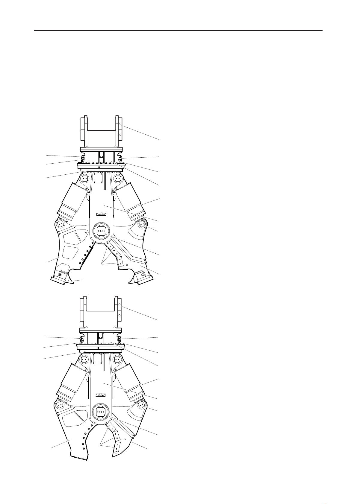
3.1 Equipment description
The illustration gives an overview of the main parts and
components of the hydraulic attachment. Actual details
may differ.
F
G
H
I
J
K
L
M
N
O
A
B
C
D
E
U
S
F
G
H
I
J
K
L
M
N
A
B
C
D
E
A. Cutter blades
B. Cutter jaw (double)
C. Four-point bearing
D. Connection function »Turn«
E. Connection »A« function »Open«
F. Adapter plate (not supplied with the hydraulic demo-
lition cutter)
G. Connection »B« function »Close«
H. Connection function »Turn«
I. Upper part
J. Hydraulic cylinder
K. Housing
L. Cylinder pin
M. Main bearing pin
N. Cutter jaw (single)
O. Tip of tooth
3.2 Function
The operation of a hydraulic demolition cutter is de-
scribed in a simplified version below:
Closing the hydraulic demolition cutter
The carrier driver operates the cutter valve, via a switch
on the floor or via a joystick in the carrier, for the function
»Close«. Line »B« is connected to the rapid movement
valve. The rapid movement valve feeds oil to the hy-
draulic cylinders. The hydraulic cylinders extend their
piston rods in fast traverse. The cutter jaws grip the de-
bris. Once the debris has generated a force in the cutter
jaw, the rapid movement valve switches to power move-
ment. The hydraulic cylinders extend their piston rods in
power movement. The debris is cut/broken. The piston
rods reach their end position.
Opening hydraulic demolition cutter
The carrier driver operates the cutter valve, via a switch
on the floor or via a joystick in the carrier, for the function
»Open«. Oil is fed to the hydraulic cylinders via line »A«.
The piston rods retract. The cutter jaws open.
Hydraulically turning the hydraulic demolition cutter
The carrier driver activates the carrier function »Turn«.
Oil is fed to the hydraulic motor. The hydraulic motor, lo-
cated in the upper part of the hydraulic demolition cutter,
causes the lower part of the hydraulic demolition cutter
to turn (cutter casing, cutter jaws, hydraulic cylinder). To
achieve endless turning of the lower part of the hydraulic
demolition cutter, there is a rotary transmission between
the upper part and cutter casing. The oil flows for the
functions »Open« and »Close« are transmitted through
the rotary transmission.

Safety and operating instructions
16 © Construction Tools GmbH | 33905197 01 | 2019-03-21
Original Instructions
3.3 Signs / labels
WARNING Missing warnings
The name plate and the labels on the hydraulic attach-
ment contain important information about the hydraulic
attachment and for personal safety. A missing warning
can lead to overlooking or misinterpretation of possible
risks and cause personal hazards. The signs and labels
must always be clearly legible.
uImmediately replace any defective name plates and
labels.
uUse the spare parts list to order new name plates
and labels.
3.3.1 Name plate
A. Model
B. Year of construction of hydraulic attachment
C. Max. permissible operating pressure »Turn«
D. Max. permissible operating pressure »Open /
Close«
E. Weight of hydraulic attachment
F. Serial number
G. Name and address of manufacturer
H. The warning symbol and the book symbol indicate
that the Safety and Operating Instructions must be
read prior to use of the hydraulic tool and in particu-
lar the chapter on Safety.
I. The CE symbol indicates that the hydraulic attach-
ment was produced in conformity with the CE. You
can find further information about this in the en-
closed EC Declaration of Conformity.
J. The EAC symbol means that the machine is EAC
approved.
3.3.2 Labels
A
B
B
A. Danger zone
B. Tightening torque
Danger zone
No persons should be within
the danger zone. Fragments of
material which come loose
while operating the hydraulic at-
tachment may be flung away
and can cause serious injury if
people are hit by them. Small
objects falling from a great
height can also cause serious
damage.
Tightening torque
ACHTUNG!
Bei Ersteinsatz neuer Zangenmesser:
Nachziehen der Schrauben nach 4h, später
nach je 40h Betriebszeit!
ATTENTION!
When using cutter blades for the first time:
Retighten screws after 4 hours, thereafter every
40 operating hours!
Drehmoment
Tight. Torque
SW /
Hex. size
10 mm = 105 +10
12 mm = 170 +15
17 mm = 530 +30
Nm
The label states the tightening
torque depending on the screw
size.

Safety and operating instructions
© Construction Tools GmbH | 33905197 01 | 2019-03-21
Original Instructions
17
3.4 Applications
U version (universal)
Field Type of application
Demolition work Light to medium-duty building
demolition, heavy-duty indus-
trial demolition (heavily rein-
forced concrete)
Cutting profiled steel (general
construction steels)
Subsequent reduction
Material separation
S version (steel cutting)
Field Type of application
Demolition work Demolition of steel construction
buildings (general construction
steels)
Subsequent reduction
Material separation
3.5 Guarantee
The guarantee or product liability will be invalidated by
the following:
• Use other than intended
• Maintenance work not being carried out or being
carried out incorrectly
• The use of incorrect consumables
• The use of non-approved parts
• Damage due to wear
• Damage due to improper storage
• Changes not carried out by or in consultation with
the manufacturer
3.6 Removing the packaging
nRemove all the packaging material.
nDispose of it in accordance with the applicable provi-
sions.
nCheck that the delivery is complete.
nCheck the delivery for visual damage.
nIf any defects are found, consult the Epiroc Customer
Center / dealer in your area.
3.7 Scope of delivery
The hydraulic demolition cutter is delivered complete
with:
• Hydraulic demolition cutter
• Safety and Operating Instructions
• Spare parts list
• EC Declaration of Conformity
Accessories as ordered:
• Hoses
Special accessories as ordered:
• e.g. adapter plate with Allen screws and pairs of lock
washers
• e.g. base plate to construct an adapter plate with
Allen screws and pairs of lock washers
• e.g. bump key to tighten the Allen screws of the
adapter plate
• e.g. hydraulic fittings for the carrier
• e.g. bolt cage to disassemble the main bearing pin
when changing a cutter jaw pair
Safety and operating instructions
18 © Construction Tools GmbH | 33905197 01 | 2019-03-21
Original Instructions
4 Transport
WARNING Hoist tipping over / hydraulic attach-
ment falling
The hydraulic attachment is heavy. The hoist/lifting
equipment and/or hydraulic attachment tipping over or
falling may cause serious injury and material damage.
uOnly transport the hydraulic attachment with lifting
equipment with the right load-bearing capacity for the
weight of the hydraulic attachment.
uOnly lift and secure the hydraulic attachment with lift-
ing gear (ropes, chains, shackles etc.) with the right
load-bearing capacity for the weight to be lifted.
uMake sure that there is nobody near or under the
suspended hydraulic attachment.
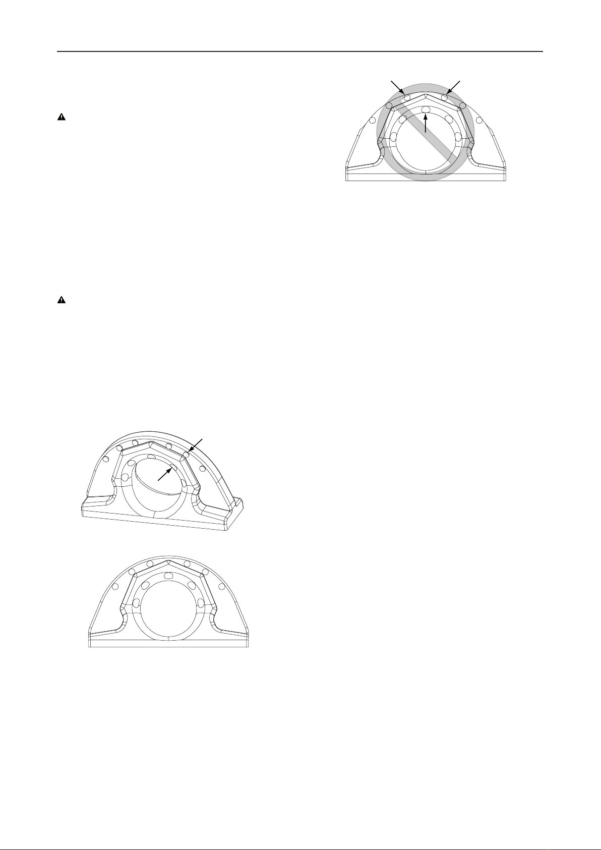
WARNING Hydraulic attachment falling
The lifting eye may fail and cause the hydraulic attach-
ment to fall. This may cause serious injury and material
damage.
uCheck the lifting eye before you lift the hydraulic at-
tachment. Never lift the hydraulic attachment with the
lifting eye if:
- the checkpoints(A) are worn and not protruding
anymoreorthe checkpoints(B) are worn and not re-
cessed anymore.
A
B
- the material is worn up to the checkpoints (A, B).
- Use
permitted
- Use
prohibited
- the lifting eye is bent.
- you detect cracks in the lifting eye or the weld
seam.
uContact the Epiroc Customer Center / Dealer in your
area if the lifting eye is worn in any way.
nTransport the hydraulic demolition cutter with the cut-
ter jaws open.
There is less oil in the hydraulic demolition cutter if
the hydraulic demolition cutter is transported with
open cutter jaws. In the event of a leak, less oil is lost
and the environmental damage is lower.
nOpen the hydraulic demolition cutter before transport-
ing it.
nIf the hydraulic demolition cutter is transported using
a crane, secure the cutter jaws with a square timber
to keep them open.
nIf the hydraulic demolition cutter is transported with a
forklift truck or lorry, secure the cutter jaws to the pal-
let with suitable strapping to keep them open.
Safety and operating instructions
© Construction Tools GmbH | 33905197 01 | 2019-03-21
Original Instructions
19
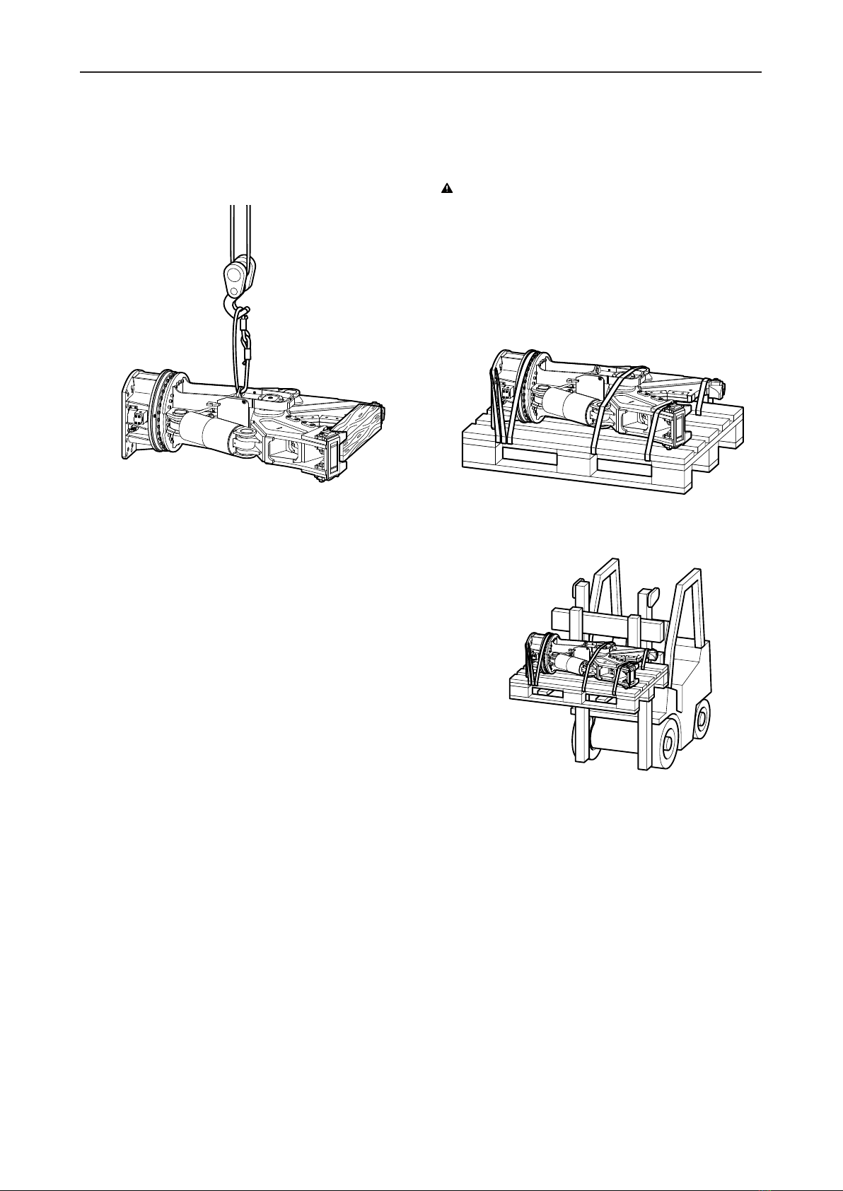
4.1 Transport using a crane
nSecure the hydraulic attachment with ropes or chains
as shown in the following illustration.
nSlowly lift the hydraulic attachment.
nPlace the hydraulic attachment on a pallet.
4.2 Transport using a forklift
truck
WARNING Hydraulic attachment tipping over
The hydraulic attachment tipping off the fork of the forklift
truck or the pallet may cause serious injury.
uPlace the hydraulic attachment on a pallet.
uStrap the hydraulic attachment to the pallet using
suitable strapping, as shown in the illustration below.
uMove the fork of the forklift truck under the pallet so
that the centre of gravity is between the prongs.
nMove the fork of the forklift truck under the pallet so
that the hydraulic attachment cannot tip over.
nSlowly lift the pallet with the hydraulic attachment.
nTransport the pallet with the hydraulic attachment to
the location provided for.

Safety and operating instructions
20 © Construction Tools GmbH | 33905197 01 | 2019-03-21
Original Instructions
4.3 Transport using a truck
WARNING Hydraulic attachment tipping over /
slipping
The hydraulic attachment slipping or tipping over and
falling from the loading area of a lorry may cause serious
injury.
uPlace the hydraulic attachment on a pallet.
uStrap the hydraulic attachment to the pallet using
suitable strapping (see illustration in chapter Trans-
port using a forklift truck).
uPlace the pallet with the hydraulic attachment on an
anti-slip mat.
uSecure the hydraulic attachment to the loading area
with ropes or chains; use any available transport
lugs.
nSecure the hydraulic attachment on the pallet and the
loading surface as shown in the following illustration.
nObserve all the applicable national/regional regula-
tions on securing loads.
This manual suits for next models
3
Table of contents
Other Epiroc Cutter manuals

Popular Cutter manuals by other brands


 Operator's manual")


Robland
Robland Silver Series manual

Siding Tools Industries
Siding Tools Industries ProKUT6 owner's manual

Sumake
Sumake ST-P6627 manual

Kaufmann
Kaufmann AUSTROFLIES 320 Instruction Manual and Replacement Parts

Gude
Gude GGKS Translation of the original instructions

Hypertherm
Hypertherm HyPerformance Plasma HPR800XD instruction manual