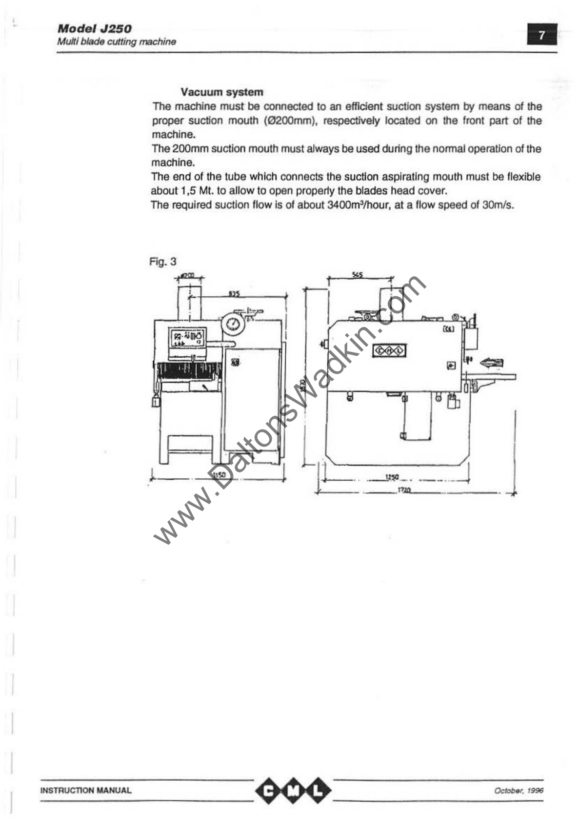
CML J250 User manual

'.
.
ModelJ250
, Multi blade wood cutting machine
,
www.DaltonsWadkin.com

Mod
el
.1250
MultibkKIe woodcllffing machi,...
INSTRUCT10H
.u.HUAI..
Ust
of contents:
Madlina
identification
warranty
Technical specilicatlons
Phonometric survey
Installation:
Suction
EJadrical wiring
Control panel
Instructions
10(
use
Wooden boards
Blades
Safety measures
Uftlng
Positioning
Usersecurity
and
reSidual
risks
Possible anomalies: identifiCation and
countefTT1easures
Ma
intenance and deanlng
Lubrication
8ectric diagrams
Spares
Enclosures Motor position diagram
Stroke-end emergency
posiUon
diagram
Lubrication diagram
Variator
Feeding
speed
display
Pog.
3
4
4
5
6
6
7
8
10
11
17
18
19
20
21
23
23
00
00
www.DaltonsWadkin.com

Model
J250
Multi
bade
wood
cUlling ml'chlllfJ
MACH
INE
IOENTIFICATION
MANUFACTURER:
DENOMINATION:
SERIALNUMBE
R:
CERTIFICATE
CE
EX
AM
TYPE:
AD
MINISTRATIVE REPORT:
CONSTRUCTION YEAR:
TOTAL INSTALLED KW:
OPERATING RATED VOLTAGE:
MAIN MOTOR POWER:
FEEDING CARPET MOTOR
PO
WER:
REDUCER TYPE:
11
:
CML
Srt
Vials delle Indusl
rte
, 2
81
8
1- 20040 CAM
81
AGO (
MI
)
Tel.:
1t*39
2 95
30
801
6
Fax: 1139 2
95
30
80
03
CE (standard maoong)
J25
0
..
!9/
Q.
f"l...
............
.
..
..
..
.
......
..
....
..
.....
..
W
0476
13
060
12 96
CERMET
Via Aldo Moro 22
1- 40068
S.
LAZZERO
01
SAVENA
BOLOGNA
19.
rf..
..
....
.
.!is.
....
..................
.
......
................
.
~I;'.
v
..
;;,;,ff~
...........................
.
Kw
.
/B,5
..
TYPE
..
U.<:h
..................
.
KW
~J.5I9.1:!;yPE
U."'1....
...
......
.
(~ybro4~
..........................
.
.....
.
matric
o
la
~i~LCi~~
•
_
..
_m
__
"_no
__
,_
...
__
,_._,
________________
~
----------------
-----~--.-
b.
-
.
_
''"
__
www.DaltonsWadkin.com

I
Model
J250
Mulliblade
wood
cuffing roachi""
INSTRucnOl-l
MANUAL
WARRANTY
The machine
Is
covered
by
a six-month warranty, slarting from the dateof delivery.
All parts that show delects
In
malerials
or
in
workmanship during this period
wi
ll be
repaired
or
replaced
lree
01
charge.
This warranty does not cover breakdowns due
10
Imnspottation,
or
caused by
electrical mlswiring. breakage
01
blades, breakdowns dueto opemtor's misusage
or
resulting
lrom
repairs performed by unauthorimd personnel.
Forwarding charges
01
parts replaced during the warranty period are to
be
charged
to the client.
TECHNICAL SPECIFICATIONS J250
Available
on
request:
"blade
position
laser
indicator
·max
passage boards width
620
Please contact ouroffices for availability, delivery terms, etc.
www.DaltonsWadkin.com

Model
J250
Multiblade woodcurting machine
INS
TRucnoN
MANUAL
Phonometric
survey
The phonomatric sUlVey was performed on a machine equipped with sound·
proofing malerials in respect ISO 7960.
For
sUlVey
dala, see altached.
"Acoustic equivalent pondered pressure PA 95 db (A)
"Inslant
sound power 100 db (A)
"Ambient correction factor K t
,9
db
NO
TE:the noisevalues shown must beregarded as edmission levels; therefore,
they do not necessariy represent safe operating levels.
www.DaltonsWadkin.com

)
Mod
el
J250
Multi
bIadtI
woodcuffing
machitlfl
•
INSTALLATION
Wftlng
The
machinebody
Is
provlcJed
with hooks that must
be
used for hoisting. Care
mus
t
be
taken
to
avoid bumps to the machine during this operation.
Fig
. 1
Positioning
The machine must be posilloned on asotid cement base. adequatelly levelled and
capable of handling the welghl
Thus, proceed with the levelling
01
the
machine
by
means
01
a precision level
tool
,
layed on the working surface.
Clamping
the
machineIsnotnecessary.
as
theweightofthemachineitself
Is
enough
to
hold the machine perlectly steady without clamping.
For a better w
or1<ing
condition
it·s
needer anlivillration
suppor1S
put
between
th
e
concrete
an
d the machines Ilaseme
nt
Fig. 2
0.:-
.
J_
www.DaltonsWadkin.com

Model
J250
MuJti
l»df
~r>g
machine
INSTRUC110H MANUAL.
Vacuum
syste
m
The machine muSI be coooected
10
an effICient suctlon system by means
01
the
proper suction mouth (0200mm), respectively located
on
the fronl part
of
the
machine.
The 200mm suction mouth must always
be
used
oor1ng
the normal operation of the
machine.
The end
of
the tube
whiCh
connects the suction aspirating mouth must be flexible
aboull,5
Mt.
10
allow to open
proper1y
Ihe blades head cover.
The required suction flow is
01
about 3400m'/hour, at a flow speed
of
3OmIs.
Fig. 3
IW
I
www.DaltonsWadkin.com

Mod
el
J250
MuIIlblade
cutting
machine
WSmucTlOH
MANUAL
E1e
ctrlcal
wiri
ng
The electrical wiring should
be
done
by
professionals:
all
the needed plans for electrical wiring are attached
10
the
present manual.
Beforeconnectlon
10
a
POwef
tinamake sure Itlatltlelinevoltage
Is
Itlesame lorthe
motors equipped
on
the machine (see plale attached
to
the machine body).
A-S·Tconnecting terminals
and
the
GNO connecting terminal
are
located
in
the
panel,a0
16 (sea page
14).
The
po
wersupply wire
mus
t
be
properly fix
ed
by
hold fas
tl
orhooking
the
electrical
sets, and protected
by
means
of
astrong
wi
ring
cable.
The electrical connection
can
be
made
by
means of aerial orunderground wires:
in
both
cases make sure that
the
wires am properly
fI)(ed.
The
body
0/ the machine must be connected to the ground.
The wires
section
must
be
able
10
han<le Itlainstalledpower, seethe following table:
-;;;;:;;;;
-
~.
-
Cut
,
.,
,,
M~
'
."".,,1
_.,
'""
~
'~
~
,....,
«
~
The ammeter shows the motor power consumption; the above table shows the
maximum values according
10
the suppfy voltage and
to
the
total installed power.
The
consump~on
values
should
not be e)(ceeded while
the
machine Is
worKing:
in
that case the feeding truck
speed
must be reduced.
Alter
the
etectrlcal connection control that
the
ralation
ctlrecIlon
0/
all
motors
is
correct, pressing: first
the
6button andaft9fawaitingfor 10seconds
turn
the
se
lector
on
poSition
I· if the
traclc
runs
In
the
direction shown
on
the
sketch underneath
the
wiring
ifs
been done corectly.
On
the
con
trary,
put
the
main
swich
on
position
O.
cut off
the
electrical power
01
the
line connected
to
the machine
and
change
posiliOl1
of
the
power
of
the
power supply
wires.
~.'
''''
www.DaltonsWadkin.com

Model
J250
Mulli
~
woodcutting machine
I~STRucnoN
MANUAL
Electrical
wiring
The electrical wiring should be done
by
professionals:
all the needed plans for electrical wiring are attached to the present manual.
Before connection to apowerline make sure that the line voltage is the
sameforthe
motors equipped
on
the machine (see plate attached
to
the machine body).
Ll-L2-L3
connecting terminals and the GND connecting terminal PE are located
in
tMpanel
#8016 (see page 14).
The power supply wire must be proper1y fixed
by
ho
ld
fast f
or
hooking
\I1e
electrical
sets, and protected by means of a strong wiring cable.
The electrical connection
can
be made by means of aerial
or
underground wires: in
both cases make sure that the wires are properly fixed.
The body of the machine must be connected to the ground.
The wires section mustbe
a~e
10
handle
\I1e
installed power; see thefollowing table:
.- 311OV-5otil. 220V-,Sotil.
OIOto<
el.do.
molot lIjoloroupp/J Aul""
..
ileh
81
.do
. m"lO,
1.1010,
auppl~
Au,.,..,ilCh
~
..
ou"on'
wl",.
..
c~on
....
ng
cumm'
..
i,.
..
..
~
..n
....
ng
(
~w
l
'"
(mm~
'"
'"
tmm~
,
.,
" Z&
.S
6.6.T
"
~g.5
,
..
"
13.5
~
5)($...T
~
~.
••
~
The ammeter shows the motor power consumption; the above table shows the
maximum values according to the suppty vottage and
to
the total installed power.
The consumption values should not
be
exceeded while the machine
is
working: in
that
caselhe
feeding truck speed must be reduced.
After the electrical connection control that the rotation direction
of
all motors is
correct, pressing: firstthe Bbutton and alterawaiting for 10 seconds
tu
rn
the setector
on
position /. if the track runs
in
th
e direction shown on the sketch underneath the
wiri
ng
it's been done corectty.
On
the contrary. put the main swich
on
position
0,
cut off the electrical power of the
line connected to the machine and change position of
th
e powerofthe powersupply
wires.
www.DaltonsWadkin.com

Mod.'
J250
M
uIlI
bIlIde
cutting
machirl8
.'
Contro
l panel
EMERGENCY STOP butt
on
Blades shah ON
.()F
F button
140
17
"027
"035
14
025
Selector 1·0-2: leeding carpet STA
RT
/STOP: the carpet will not start
if
the
blades shah is stopped.
14
029
,
<0,
1401 1
14012
14017
WARNING:
Position: 0 stop
1 leeding speed
2 fast
feed
ing speed
Ammeter
Blades door timer blinking light Indicator
Hand-wheel
fO(
lowering-uppering group rollers pressure
Pressing group height milllmitered scale
Index
first sawblade
The
machine
will nOI Sla
rt
under
one
of
the
following
co
nditions:
• EMERGENCY STOP
butt
on press
ed
• Blades access d
oo
r or feeding carpet access
do
or opened
www.DaltonsWadkin.com

Model'
J2!SO
Mulli
bIadtJ
cutting machine •
INSTRUCTION MANUAL
INSTRUCTIONS
When the operations explained In the 'Installation' chapter have been made, the
machine
Is
ready
for
working.
Fojlowlng are listed -
in
the right
order
-all the operations that must
be
made
to
operate
the
machine.
Select
the
neededblade diameter. The following table shows the maximum cutting
thicknesses according to the blade diameter:
Blade
diameter
Max
cutt~
thi::kness
Oevce
lor
with
fj)(
blades
short
pieces
el220mm 4()mm -
0250mm
55mm
30
el300mm 80mm
55
With the main Switch set
on
the position 1push the EMERGENCY STOPbutton and
wait until
the
blades access door
ijmer
unlocks the
~ades
access door itself (the
bflnking
indicator
shows that the
door
Is
unlocl<ed).
"Open
the blades access door No.
1407
.·Make
sure
that the wood boards are locked
in
their places, and lined
up
with the
pressing group. It is important that the wood boards are made according to the
attached drawing (see attached:
Wood
boards'), and madeof undelormable wood.
•Assemble!heblades
assy
a'lditsspacers oolyon
!hespirde,
att9l"havingatrefuOycleaned
the
tGdes
and spacerwith a
d-y
doth.
"When
the blades ass'yis assembled, lockthe threadedlocking ring2 onlyby means
of
the specific tool supplied with
lt1e
machine.
··According
to
the diameter
of
the mounted blades, lift the main shaft operating on
the manual wheel 14031 (see page 14) to
al
lowthe assembJyofthe
sawon
its
shaft
Warning:
never
usa hammers
or
simil
ar
tools to facilitate this operation, as it
is
supposed to be performed as gently
as
possible.
Furthennore. theshaftmustbecarefullycleanedusing rags:
aVOid
blowing
lt1em
with
compressed air that would raise dust that anyway falls back. When the saw have
been positionedon theshaft, lockit
by
means of thespecial nng nul which has been
previously cleaned.
www.DaltonsWadkin.com

Model
J250
Milkl bI6do
-..od
cuttingmachine •
lN
STRUCllON
MANUAL
Check, operating
on
thedisposal
'8005
bymeans
01
the
55rnm
wmoch
supplied
with
themachine,
the
cormct
functioning01the splinterproofsecuritydisposals, that-due
to thelrown weight -should always fall perpendlcularty
to
the
feeding truc!<,
Furthennore,
check
thatthe spllnterproofs located
on
th
e
wor1ollng
surface
can
easily
slide according to their function.
Close
the
blades access
dool""No.
1407.
·.get the reference guide
No
. 1
40
19atthe feeding sideof
the
machine,operallng
on
the handle No.
14022.
and referring to the specific milllmlt
ered
rule
r.
..Re-press
the
EMERGEN
CY
STOP
button.
~
Sta
rt
blades rotation pressing the
button
No.
14035(see attached 'Control panel').
•
Se
t the pressing rollers heig
ht
operating the hand
......neel
N
o.
1401
t
(see
on
the
attached 'Co
ntrol
panel)
ac
cording
to
the nominal
thi
c
kness
of
the
boards
to
be
wor1<.ed:
t
he
specific scale N
o.
14
0t
2
shows
tI1e
height position
of
the rollers.
Should
the
short boards disposal beassembled
In
th
emachine, the height setting of
thepressing
rol
lersmustabsoluteiynot
exceed
thevalues
shown
In
the
table,
in
on:jer
to
avoid
possi
ble damages.
Jt
Is Impo
rt
ant that
th
e
working
boards
are
not supposed
to
exceed the
nominal
thiCkness
formore
1han±1
Omm
,both~ thickness anddltfonnl
ty.
00
th
econtra'Y, the
mach
in
e
can
get
damaged,
and
unsafety for the operator.
"
Un
lock
the
handle No. 1
4006,
than
staTtJowering
the blades
sh
aft,
operaUngon the
hand
wI1eel
LNo.
1"4031,
controll
in
g
at
the
same
time
the scale
sho
wn
by
the arrow
indicator
No
.
14Q371ocaled
neart
he
wh
eel,
until thecorresponding size diamet
er
of
the blades
assem
bled I
nto
th
e machine
Is
reach
ed.
Then
lock
again
the handle
No
.
14036
.
• Start
the
feeding
carpel pressing the
button
N
o.
1
4025
(see
on
attached 'Control
panel'); the leedngspeed will be set by
means
of t
he
selection:
on
position t (slow
speed)
an
dli
the
workingcondition ablows
to
work
with
afaster
speed
put
on
position
2 (f
as
t
speed).
"Startthe
cu
tting,settingtheboards
Into
the
machin
e,
payingattention
to
the
linearity
with
th
e
re
fe
rence
guide, becau
se
once they are
cough
t
by
the
feed
ing
truck.
they
cannot
be
set
differently.
Never
feed
boards laidoneon top
the
ot
h
er,
and
never
exceed
tI1e
bl
ades
operating
~mits
:
not
observ
at
ing
these
rules
drastically reduces the working quality,
and
may
cause
damages to the machine.
The
ammeteris specifiCally provided
on
the
'Con
trol
panel' toconstantly display
th
e
power
consump
tion
of
the motor that
opera
tes
blad
es.
Th
e
m8.l(im
um
estimate values
are
sho
wn
in
the
table
on
page
8.
The
limiting
wi
dtl1
device located at the
feeding
side
of
the machine
is
provided with
a
mIcroswitch
Fc5 (
see
atta
ched
'Position
mic
ros
wit
ches
and
em
ergencies') Itlat
slops the machine
whe
n put
In
to action.
www.DaltonsWadkin.com

•
~
~
~
1401
~""
It:13
s.an,.
....
-"
f
~
~
1«11
.o.epllii\l-a.
1405
Uppo"n.lO<I:bodo:-.;c.
I
It)&
W~
.....
l
~
!
1401
Kood..".
,
10l0I1
~Ior~and
i
Io:JooIm;
f""Mi1g
""""
III""P
HO\2~~~
1<1015
P
....
~bo..:I
i
1<1016
E~
be
"lo",
14011
FI'1IbIodendo.
1401
'
SlNI....,
l<IOlt
FtIlCt
IQ)
~
riGot
bott
1402S
F~
CAIpIj
STAflTIS~
1«21
AIIftooj.
1«00
...
MddI
\«11\
9IocIIillilgIIwI<WIIII
14C05
8IJdoo
......
1uIon
!i
11407 \
1dn'l.
\
1I1n'J'l
\
-1
An..:.
,,
14UHf
I
r
~
la
d"
www.DaltonsWadkin.com

,
•
~
~
U()l
y,*",
Iin¥>
!
0
,~
...
~.
•
1403
Soc:trly
doMco
.-
0
1404
A$fU:O;m<x.Ih
.
~
•
[
~
•
140
15
14
031
1405
Upp<{
d-kictba::tdoYiclo
•
• I /
14011
1406
'(i
~..oo.
0 1404
1107
liNd"*<1Of 0
• 1
c
14011
~fQ"~ancI
~f'eosflg""'~
14012
Iland.rIhoeItIJiIg
II'i<:Moos
~
14/)13
I(noIl
141115
PMIOIOOIWIboaro
j
14016
EIearicalbol"loOl
140
17 FnlbiadoO:lo"
14016
SIeoIfngen
1401~
GldhotJor
lWl
F..,.
14022
~
twde
Ira
l«1l3
lowOllflli.kictbld<
14024
PIololl'Ji;lOhoIdor
14025
F~carpMSTAAT/sTOP
lW7
Emocgoncybulloo
1~
~
..
14OO(l
l.I.u
....
ch
14(lJ
1
BIado
fiI;
hardot.ooI
14Oi2
Hingocarpo!door
14043
Ca,pot
cIoo!
l
.'
!
www.DaltonsWadkin.com

•
•
.
~
~
lm~
.....
~
.
~
1
4031
1403:
1404
~..,..,
f
~
/
4038
1405
Mtlbboct_
i 14032 I 1409 1
401
Hudtoo\olr
I
~
I / 1403
.0
Ca/pIj
boct
.....
•
14013
""'"
"
••
A •
--
0
14(
14031
IIo<iIIiIWFJ
t-n:tot.ooI
l
14032
OI~
14031
C..".
i
14042
tr..,.~<b>I
lo104J
CarpoIdoor
j
f
i
www.DaltonsWadkin.com

I
~
14
031
-
It
14032
14033 _ •
~
\
14
036
~
•
14
037 " •
~~
1";::..If$
~,
~
0
,,~
0
"
~ ,
/ p
~
~lt
vt
14
04
Q;
1403
g/
J 14038
14
09
14044
i
1404
~
~
I?
1407
1404
J."I9~
11/111
1t.4
....
14011
CMpoI
tJo<i_
l.aJl
EIIodo.lllinihond
olwl
1~
OIjQJIp
liCW
110.-_
I'-
LocIIi'1ghW.hool
liOO1
BIodor<lornll«iPu
,
...
c..,.
''''
......
14040
M
otor
if
-
..
f
~
l
~
i
~
I
www.DaltonsWadkin.com

Model
J:l!50
Mult
i
bItM:HJ
'tIIIIJOd
cutting
mac
hif16
Wooden boards
t-,
I
I
_
~-----,-I
f-
- -
I
,
~
LL,
-l#---
,
~
I
Ll
1' ,
if
:
...
U
~
1'1-
-
. I"
I
';JL
...
,w
,J
.1JJ-
_
.
,_~
__
mo
__
.
_NN_~
____________
~
______________
~~=~~
"
=_
www.DaltonsWadkin.com

Modo"J250
Multiblade woodcutting machine
Blad&
I
~STFlUC'T10N
MA~U"'L
www.DaltonsWadkin.com

Mod
el J2!JO
Multi
bIadIJ
wood
cutting
machin8
S
AFETY
MEASURES
The machine is provided with a specific terminat for ground oonnectlon.
Apre-settimerprevents theopening
01
the
btades
access
door,
but
when
the
btades
have
come
to
a complete stop.
The timer is pra-set
on
60 seconds,
and
!his time cannot be
changed.
Othersecurity sensors are foreseen
as
follows:
a)
ctosed
door
con
firming sensorSOt (see
'M
icroswitches and emergency)
b)
positive sensor that
preven
ts
th
e machine starting
If
the
blades
access door
is
opened
502
(see 'Mlcroswltches and emergency')
c)
microswitch of the plank passage limiting disposal Fc5 (see "Mlcroswitches and
emergeocy')
Thefee<ing truckcan be
Ql(cluslvety
startedaftertheautomaticswitching 'star-delta'
01
the
motor that
moves
the
blades shaft
The height selling
01
pressing rollers while working should be avoided.
In
case
01
electric overload. a relay
stops
the machine:
It
Is
I"IOt
recommended
to
Increase
the
'thelTTllc'
In
order to
a~pId
blades blocklf!g inside wood.
Aftera black-out due
to
any
possib
le
cause,
oralteran
emergency stop caused by
one
of
Ihe security sensors,
the
machine
can
only be re-started wllh
an
Intentional
action
of
the user.
The electrical panel door
can
only be
opened
when
the
main
switch Is set
on
the
positioo
O.
www.DaltonsWadkin.com

•
Model
J250
Multiblade
wood
cutting machill6
USER
SECURITY
AND
RESIOUAL
RI
S
KS
~oever
sel
over1ap
boards
"steady supports (li
ke
trestles
or
similar) should
be
used at the feeding and at the
output side 01the machine In case
of
working
01
very
loog
planks.
~
never
exceed the
±IOmm
tolerance on the nomInal thickl1ess shown by the G
Indicator.
~never
use unbalance
orwom-out
blades.
..
every tum-.ovar 01wo
n.:
check that the anti·kick
bac!c
fall
in
their proper position
undertheir weight
effect
·wh
ile operating the machine always wear safely shoes and a leath8f vest
Atways use safety gloves and proper protectioo
wh
ile
assembling or changing
blades.
--
during
any
ki
rl(!
of
prepa
rati
on
workor
ma
intenance Ihemainswitch
must
beset
on
the position
O.
If the machi
ne
is
not being used, or
If
it is stopped due to a breakdown
or
for
maintenance ,it isadvisable 10 lock
It
and toprovide a
sign
in<iCating
the
reason
tor
which the machine cannot
be
slaned.
www.DaltonsWadkin.com
Table of contents
Other CML Cutter manuals