2-8-4 Berkshire Passenger Train Set Inventory
• 2-8-4 Locomotive
• Tender
• Two passenger coaches
• Observation car
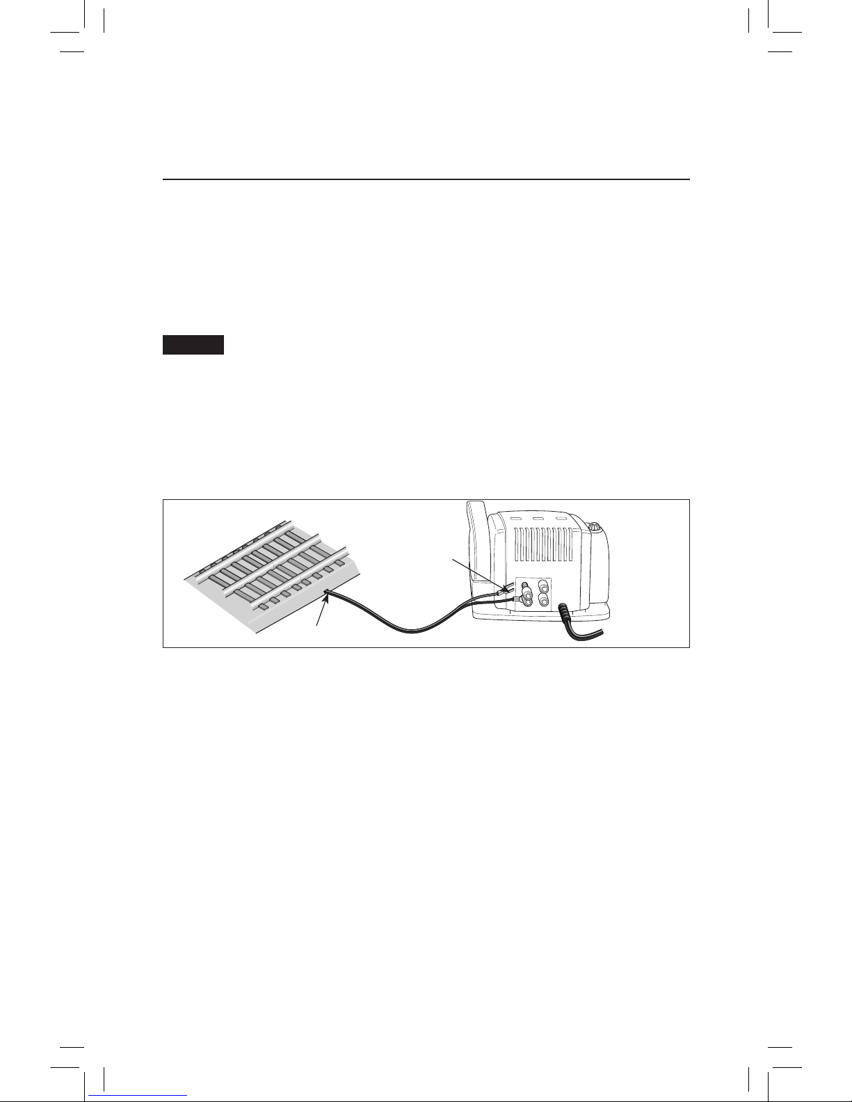
• CW-80 transformer
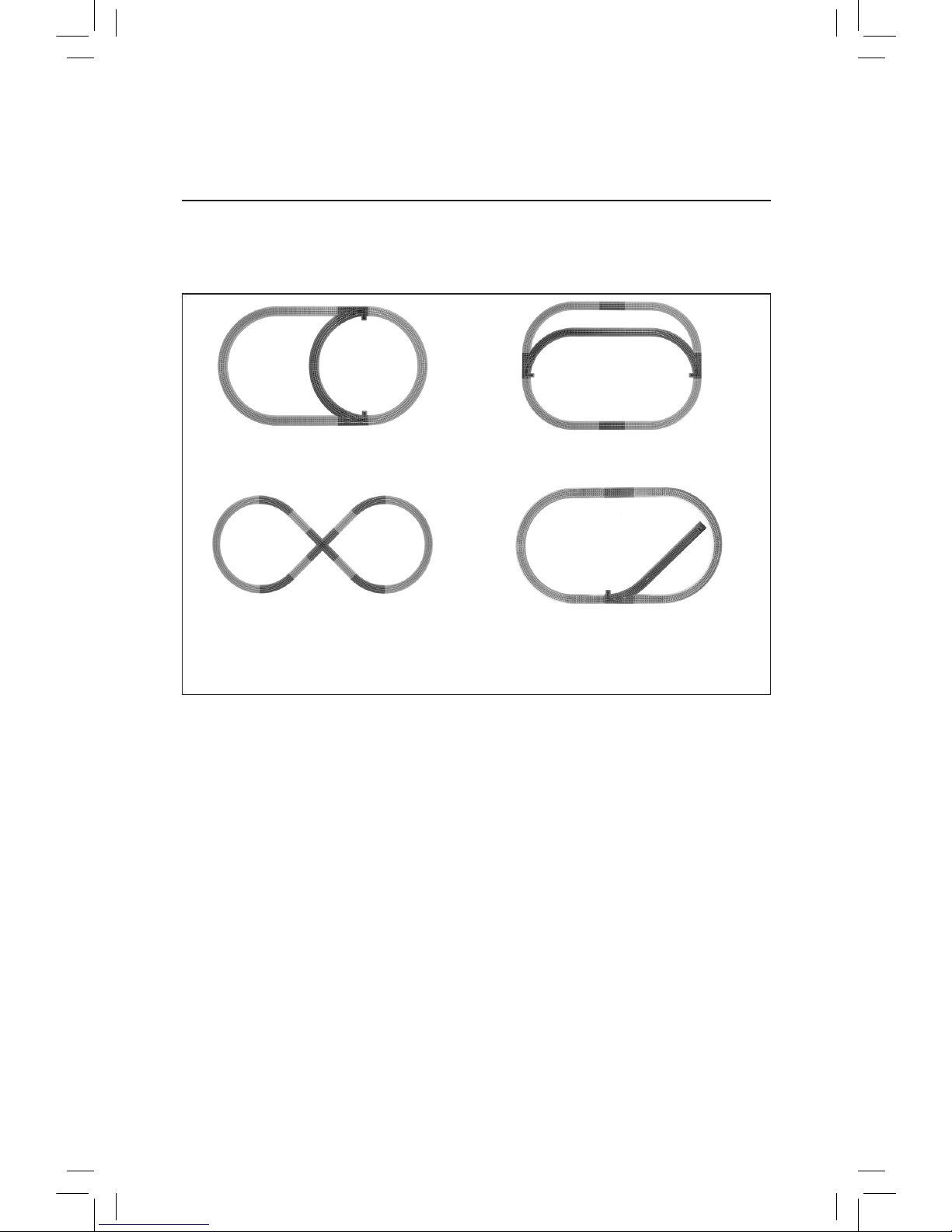
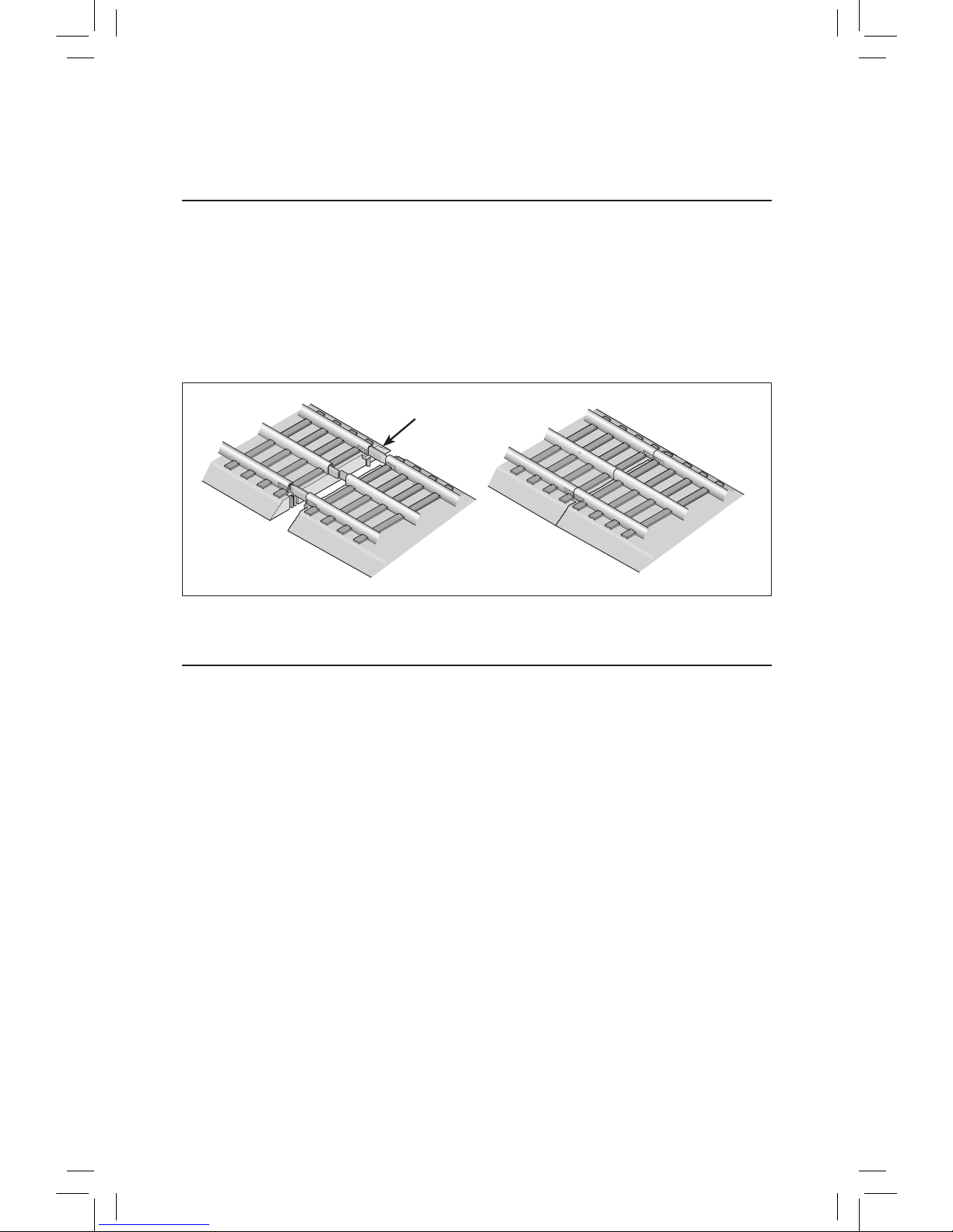
• Three straight FasTrack track sections
• Eight curved FasTrack track sections
• One FasTrack terminal track section
• Smoke fluid
• Replacement traction tire
• Owner’s Manual
• DVD
Congratulations!
2
Congratulations on your purchase of the Lionel 2-8-4 Berkshire Passenger Ready-To-Run Train
Set! This set features everything you need to get started—a CW-80 Transformer, a huge loop of
easy-to-assemble FasTrack track, a string of detailed cars, and a powerful Lionel locomotive.
Have fun growing with this complete train set! Start with the set components, then follow your
imagination into your own miniature world. Expand your railroad empire with additional FasTrack
track sections, enhance your layout with accessories, lengthen your consist with extra cars, or operate
a new locomotive at the head end of your train! Explore the possibilities at your authorized Lionel
dealer.
Use this Owner’s Manual to learn how to set up, operate, and maintain your train set for years of
reliable operation.
The transformer included with this set should be periodically
examined for conditions that may result in the risk of fire, electric
shock, or injury to persons (such as damage to the output cord,
blades, housing, or other parts). In the event that such conditions
exist, the transformer should not be used until properly repaired.
Parents!
The following Lionel marks are used throughout this Owner’s Manual and are protected under
law. All rights reserved.
Lionel®, LEGACY™, FasTrack®,TrainMaster®, Odyssey®, RailSounds®, CrewTalk™, TowerCom™,
DynaChuff™, StationSounds™, Pullmor®, ElectroCoupler™, Magne-Traction®, CAB-1®Remote
Controller, American Flyer®, Lionel ZW®, ZW®, MagniVision®, TMCC®, Lionelville®, Wireless
Tether™, Powerhouse™, LionMaster®, Conventional Classics™, Postwar Celebration Series™,
TruRail™, PH-1 Powerhouse®, Powermaster®, Powerstation-Powerhouse®, Accessory Motor
Controller™, AMC™, Accessory Switch Controller™, ASC™, Action Recorder Controller™, ARC™, Track
Power Controller 300™, TPC 300™, Track Power Controller 400™, TPC 400™, Block Power
Controller™, BPC™, Operating Track Controller™, OTC™, FatBoy™, Lionel Lines®, Joshua Lionel
Cowen Series™, Lockon®, TrainSounds™, MultiHorn™, MultiWhistle™, Choo-Choo™