Lippert Components ABOVE FLOOR SLIDEOUT SYSTEM User manual

Above Floor Slide‑out
(vertical motor)
OEM INSTALLATION MANUAL

Rev: 11.27.19 Page 2 CCD-0002710
TABLE OF CONTENTS
Introduction 2
Safety 2
Resources Required 3
Preparation 3
Installation 4
Room Stop Adjustment 7
Slide Room Installation 8
Mounting and Switch Wiring 9
Post-Installation Check 9
Operation 10
Extending Slide-Out Room 10
Retracting Slide-Out Room 10
Hard Stops 10
Troubleshooting 11
Slide-Out Concerns 11
Syncing the Slide-Out 12
Switch Related Concerns 14
Motor Unit Concerns 14
Wiring Diagram 15
Introduction
The LCI Above Floor Slide-out (Vertical Motor) system is a rack and pinion style slide system. Utilizing a bi-
directional electric motor to actuate the drive shaft, the slide-out room is extended and retracted from the
same source. The actuator has a built-in automatic braking feature.
For information on the assembly or individual components of this product, please visit:
https://support.lci1.com/lci-above-floor-slide-outs .
NOTE: Images used in this document are for reference only when assembling, installing and/or operating
this product. Actual appearance of provided and/or purchased parts and assemblies may differ.
Safety
Read and understand all instructions before installing or operating this product. Adhere to all safety labels.
This manual provides general instructions. Many variables can change the circumstances of the instructions,
i.e., the degree of difficulty, operation and ability of the individual performing the instructions. This
manual cannot begin to plot out instructions for every possibility, but provides the general instructions,
as necessary, for effectively interfacing with the device, product or system. Failure to correctly follow the
provided instructions may result in death, serious personal injury, severe product and/or property damage,
including voiding of the LCI limited warranty.
The "WARNING" symbol above is a sign that a procedure has a safety risk involved and may cause
death or serious personal injury and/or severe product and property damage if not performed
safely and within the parameters set forth in this manual.

Rev: 11.27.19 Page 3 CCD-0002710
Failure to follow instructions provided in this manual may result in death, serious personal injury
and/or severe product and property damage, including voiding of the component warranty.
Unit MUST be supported per manufacturer's recommendations before working underneath. Failure
to do so may result in death or serious personal injury.
Always wear eye protection when performing service, maintenance or installation procedures.
Other safety equipment to consider would be hearing protection, gloves and possibly a full face
shield, depending on the nature of the task.
Moving parts can pinch, crush or cut. Keep clear and use caution.
Resources Required
• Cordless or electric drill or screw gun
• Appropriate drive bits
• ⁄" - 1 ½" full threaded bolts
• ⁄" SAE flat washers
• ⁄" nylon locking nut
• ⁄" hex wrench (stop block set screw)
• #8 - 32 x 1" full threaded bolts
• #8 SAE flat washers
• #8 - 32 flange nuts
• ⁄" wrench
• ⁄" wrench
• 1 ⁄" wrench
• #8 x 1" self-tapping screws
• ½" drill bit
• 1 ⁄" drill bit
• Jig saw or saws-all
• Heat gun (electrical connections)
• Crimp butt connectors
• Crimp tool
• Marking method
The “CAUTION” symbol above is a sign that a safety risk is involved and may cause personal injury
and/or product or property damage if not safely adhered to and within the parameters set forth
in this manual.
Preparation
1. Make sure unit is parked on solid, level ground.
The unit MUST be supported per manufacturer's recommendations before working underneath.
Failure to do so may result in death, serious personal injury and/or severe product or
propertydamage.
2. Make sure the unit is level and supported in accordance with manufacturer's recommendations.
3. Inspect slide-out mechanism to make sure that all stop blocks are intact and that there are no missing/
damaged parts.

Rev: 11.27.19 Page 4 CCD-0002710
Installation
1. Locate the slide-out assembly or assemblies as per OEM design. For a single assembly, center the slide-
out assembly (Fig. 1) in the slide-out opening.
NOTE: Slide openings are determined by the OEM.
Fig. 2
Fig. 1
2. Mark the locations of the four mounting bracket's pre-drilled mounting holes for the drive-side
(Fig.2A) and idler-side (Fig. 2B) on the unit's main floor.
BB
BB
AA
AA
Drive Side
Drive Shaft
Idler Side Outer
X-Shaft

Rev: 11.27.19 Page 5 CCD-0002710
3. Mark the locations of the drive-side (Fig. 3A) and idler-side (Fig. 3B) adjustment assemblies.
4. Mark the location for an access opening on the unit's main floor to accommodate the placement of the
vertically mounted drive-side motor (Fig. 3C).
5. Use a 1/2" drill bit to drill the eight mounting bracket through-holes located in step 2.
6. Use a 1 3/8" drill bit to drill the two clearance holes for the adjustment assemblies located in step 3.
7. Use a saw to cut the vertical motor's access opening located in step 4.
Fig. 3
8. Set the drive-side motor assembly into its access opening and the adjustment assembly into its
clearance hole.
A. Align the mounting bracket's through-holes with the drilled holes in the floor.
B. Fasten the drive-side mounting bracket to the floor using OEM-supplied 3/8" - 1 1/2" bolts, 3/8"
SAE flat washers and 3/8" nylon locking nuts.
NOTE: Maintain parallelism between dual slide arms. If applicable, for dual assemblies it is critical that the
assemblies be installed (timed) so that the slide-out room extends and retracts evenly.
9. Set the idler-side adjustment assembly into its clearance hole.
A. Align the mounting bracket's through-holes with the drilled holes in the floor.
B. Fasten the idler-side mounting bracket to the floor using OEM-supplied 3/8" - 1 1/2" bolts, 3/8"
SAE flat washers and 3/8" nylon locking nuts.
NOTE: Maintain parallelism between dual slide arms. If applicable, for dual assemblies it is critical that the
assemblies be installed (timed) so that the slide-out room extends and retracts evenly.
A
B
C

Rev: 11.27.19 Page 6 CCD-0002710
10. Make sure the slide-out assembly is level prior to installing the slide room.
11. Use the drive-side (Fig. 4A) and idler-side (Fig. 4B) adjustment assemblies to set the slide-out
assemblylevel. This adjustment will correct any tilt in the slide-out.
Fig. 4
A
B

Rev: 11.27.19 Page 7 CCD-0002710
Room Stop Adjustment
Adjust the room to desired location as follows:
1. For "out" stop (Fig. 5A) and/or "in" stop (Fig. 5B) adjustment, use a 3/16" hex wrench to loosen the
stop's set screw (Fig. 5C) on the stop block (Fig. 5D).
2. Adjust the stop blocks to desired location.
3. Tighten the set screws.
Fig. 5
A
Top View of Stop Blocks
Bottom View of Stop Block
B
C
D

Rev: 11.27.19 Page 8 CCD-0002710
Slide Room Installation
1. Place room on top of the hat channel(s) (Fig. 6). Center the room in the slide opening.
NOTE: Make sure the room is centered before securing room to hat channel(s).
2. Locate the set of front slide-out mounting holes (Fig. 6), in the hat channels, closest to the front of the
slide-out and maintain room alignment. Secure the room to the hat channel(s) with OEM-supplied
#8 - 32 x 1" bolts, #8 SAE flat washers and #8 - 32 flange nuts.
3. Locate the set of rear slide-out mounting holes (Fig. 6), in the hat channels, closest to the rear of
the slide-out and maintain room alignment. Make sure dual slide-out assemblies are parallel to one
another when securing the room to the hat channels. This will help ensure smooth operation of the
slide-out room. Secure the room to the hat channel(s) with OEM-supplied #8 - 32 x 1" bolts, #8 SAE flat
washers and #8 - 32 flange nuts.
4. Locate the front and rear interior slide-out mounting holes (Fig. 6) in the hat channels. Secure the
room to the hat channel(s) with OEM-supplied #8 bolts, washers and flange nuts.
Fig. 6
Hat Channels
Drive-sideIdler-side
Rear Slide-out Mounting Holes
Rear Interior Slide-out Mounting Holes
Front Interior Slide-out Mounting Holes
Front Slide-out Mounting Holes

Rev: 11.27.19 Page 9 CCD-0002710
Mounting and Switch Wiring
Depending on OEM requirements, the slide-out room may be operated using a rocker switch (Fig. 7).
1. Determine where to mount the user interface. It can be mounted anywhere inside the unit. The
mounting location must be watertight.
2. Install the user interface per OEM recommendations using two OEM-supplied #8 x 1"
self-tappingscrews.
Fig. 7
3. See the Wiring Diagram section in this manual for wiring instructions.
NOTE: Additional wiring MUST use 10 AWG minimum and conform to current RVIA electrical standards.
Post-Installation Check
1. If operating a motorized coach;
A. The PARKING BRAKE must be engaged.
B. The transmission must be in PARK.
C. The on/off ignition position (Class A and C; Gas and Diesel) is determined by the OEM of the coach
being serviced. Contact the OEM of the coach for the correct ignition position for this procedure
before proceeding.
Moving parts can pinch, crush or cut. Keep clear and use caution.
2. Make sure the slide-out room path is clear of people and objects before and during operation of the
slide-out room.
3. Always keep away from the slide rails when the room is being operated. The gear assembly may pinch
or catch on loose clothing causing personal injury.
4. Keep stored items in compartment clear of slide-out motor mechanisms and wiring to prevent
interference of slide-out operation.
5. The 12V DC battery disconnect should be in the ON position.
NOTE: Batteries MUST be tested under a load to get an accurate reading. Use a multi-meter to ensure the
battery is fully charged, the multimeter must read 12.5V - 12.7V DC for a full charge.
6. Make sure the unit is level.
7. Extend and retract the slide-out to verify correct hard stop positions and good seal of the retracted
room to the unit. See Operation section.

Rev: 11.27.19 Page 10 CCD-0002710
Operation
Make sure the unit's T-molding and interior (determined by OEM) are installed prior to operating the
slide-out. Make sure the battery is fully charged and hooked up to the electrical system.
Extending Slide-Out Room
1. Press and hold the rocker switch in the OUT (Fig. 8A) position until the room is fully extended and
stops moving.
NOTE: Only hold the switch's OUT position until the room stops.
2. Release the switch, which will lock the room into position.
3. Check hard stops for proper location and desired extension of the slide-out.
Retracting Slide-Out Room
1. Press and hold the rocker switch in the IN position (Fig. 8B) until room is fully retracted and
stopsmoving.
NOTE: Only hold the switch's IN position until the room stops.
2. Release the switch, which will lock the room into position.
3. Check hard stops for proper location and desired retraction of the slide-out.
Fig. 8
A
B
Hard Stops
Without hard stops, the interior trim and the outside slide flange become soft stops and can be damaged
since the slide controller or motor clutch will not be able to shut the system off.
The hard stop will allow the motor to clutch, or the control box to sense the amperage spike, when the slide
motor is stopped. The stops shut down the slide-out system, protecting the drive shaft, shaft bolt and the
crown gear.
Room extension adjustments are made by repositioning the stop blocks on both ends of the hat channel.
A ⁄" hex wrench is used to set stop block positions. Go to Room Stop Adjustment section for instructions
on how to set hard stop locations to ensure proper slide-out seal-in and seal-out.

Rev: 11.27.19 Page 11 CCD-0002710
Troubleshooting
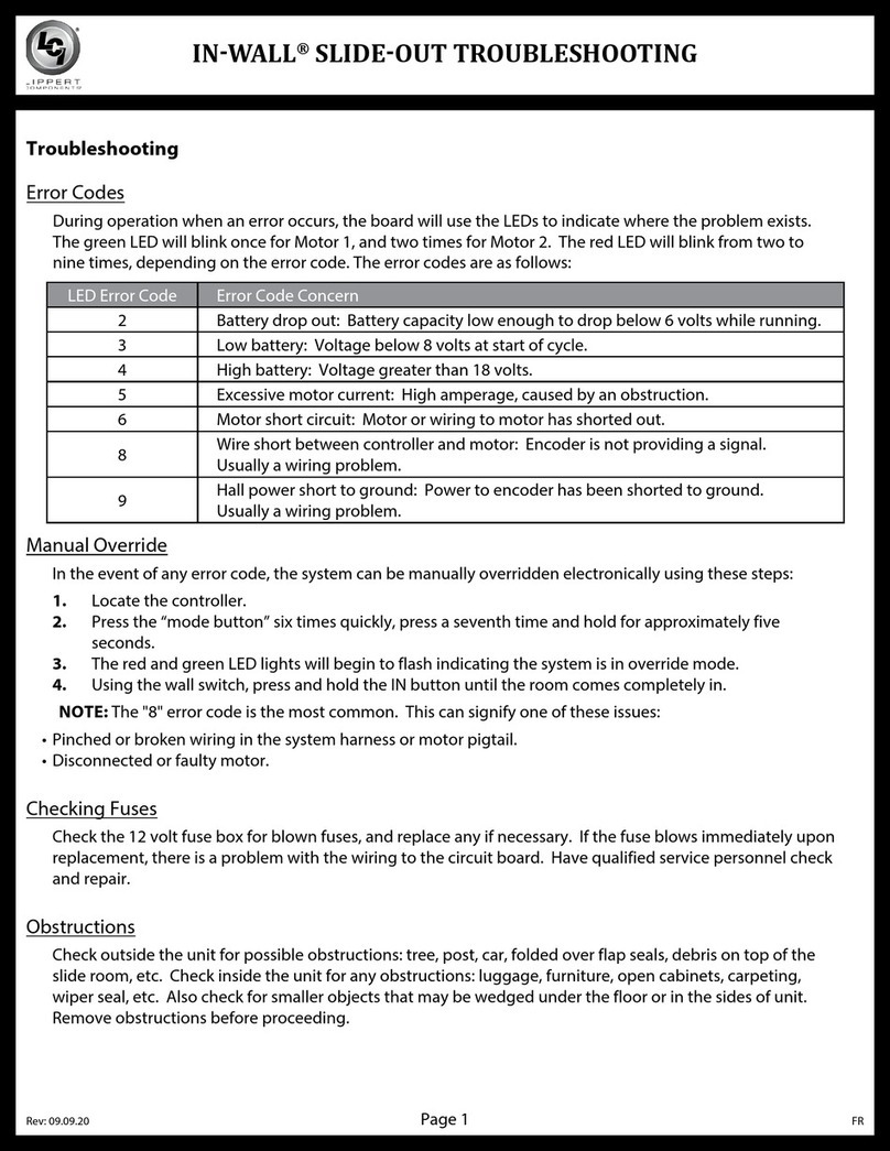
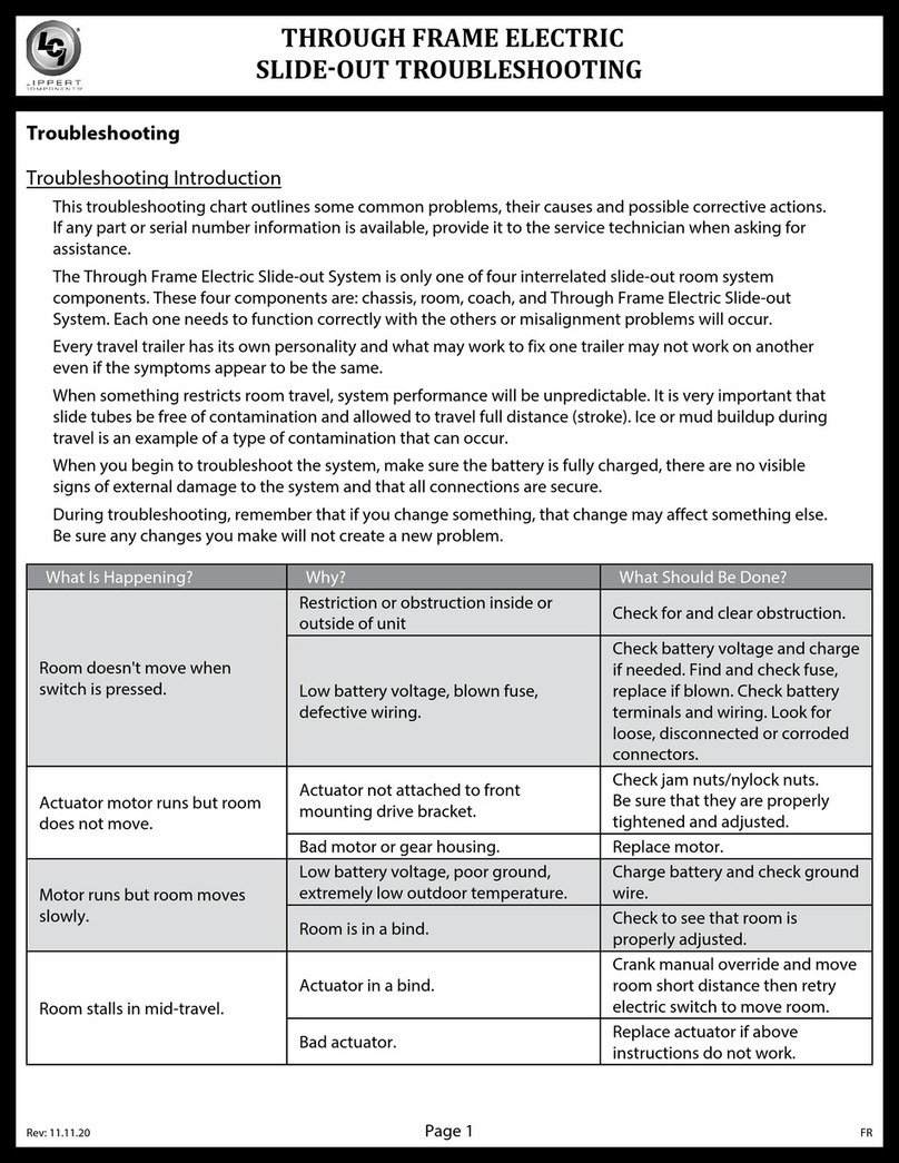
If, after slide-out assembly and slide-out room installation is complete, slide-out does not perform as
expected, make sure the battery is fully charged then for check the following:
• Slide rails and rack and pinion are free of dirt, debris or other types of contamination restricting travel.
• No visible signs of external damage to the motor, assembly or rails.
• The motor is wired properly and all connections are secure.
During troubleshooting, changing, altering or adjusting one component may affect another. Make sure any
changes do not create a new problem.
Slide-Out Concerns
During retracting of the slide-out, if the top or bottom of the room hits the opening before its opposite side
does, then the room is tilted and must be re-leveled. The drive-side and idler-side adjustment assemblies
(Figs. 3 and 4) may require an adjustment to one or both of the adjustment bolts.
1. Use a 1 5/16" wrench to back outloosenthe 7/8 - 14 UNF jam nut (Fig. 9A) a few threads.
2. Use a 9/16" wrench on the adjustment bolt (Fig. 9B) to raise or lower the tilt angle of the slide-out until
the slide-out is level.
NOTE: Check level of slide-out after eachadjustment.
3. After the slide-out has been leveled across the drive-side and idler-side, tighten the 7/8 - 14 UNF jam
nut (Fig. 9B) against each base's fixed stop nut (Fig. 9C).
4. Do a final level-check on the slide-out before operating the slide-out for tilt adjustment verification.
Fig. 9
C
A
B

Rev: 11.27.19 Page 12 CCD-0002710
2. At the motor end, use a 7/16" wrench to remove the 1/4" - 20 bolt (Fig. 10A) and nylon locking nut
(Fig.10B) from the outer x-shaft (Fig. 10C).
NOTE: This is the part that allows the follow slide to be adjusted, pulling the room closer to or further away
from the wall at the idler end.
Fig. 10
Syncing the Slide-Out
When the two opposing sides of the slide-out are misaligned—out-of-sync—an adjustment can be made to
realign—sync—the system by performing a manual adjustment of the outer x-shaft (Fig. 1).
Before accessing the power unit, make sure power to the system has been disconnected.
The slide-out adjustment for syncing the LCI Above Floor Slide-out is handled through the drive shaft(Fig.
1).
To sync the slide-out system, do as follows:
1. Access the slide-out's drive-side rail assembly (motor end) (Figs. 1 and 3).
NOTE: The slide-out shaft will be accessible from the inside of the unit. The slide-out motor and mechanism
are accessible from the outside.
Always disconnect battery from system prior to manually operating system. Failure to disconnect
battery can cause electricity to back feed through the motor and cause serious damage to the
system as well as voiding the warranty.
A
B
CMotor End

Rev: 11.27.19 Page 13 CCD-0002710
Motor End
Motor Drive Shaft
Outer X-Shaft
Rotate X-Shaft
to Align Holes
Outer X-Shaft
Lock Nut
Hex Bolt
Fig. 11
3. Turn the outer x-shaft (Fig. 11) to rotate the drive shaft until the idler-side end alignssyncswith the
drive-side end.
4. Align the closest hole on the outer x-shaft with the through-hole on the drive shaft (Fig. 11),
then reinsert the previously removed (step 2) 1/4" - 20 bolt and locking nut (Fig. 12) to secure the
syncedslides.
Fig. 12
5. Reconnect internal and external power to the unit.
6. Using the switch (Fig. 8), operate the slide-out system to make sure the drive-side and idler-side are
properly synced.
7. If rail assemblies remain out-of-sync, repeat steps 1-6 until both rail assemblies become synced and the
room operatesnormally.

Rev: 11.27.19 Page 14 CCD-0002710
Switch Related Concerns
If slide-out moves opposite from what the rocker switch's switch plate indicates, reverse the wires from the
motor on the back of the switch. Wire size must be 10 AWG minimum. See Wiring Diagram.
NOTE: The use of heat shrinkable butt connectors, a crimp tool and a heat gun may be required to
complete the reversed wiring connection.
• Black wires are ground
• Yellow wire is "out" or extend
• Green wire is "in" or retract
• Red wire is power
Motor Unit Concerns
Before attempting to troubleshoot the power unit, make sure an adequate power source is available. Do
NOT attempt to troubleshoot the power unit without assuring a full 12V DC charge.
NOTE: Batteries must be tested under a load to get an accurate reading.
The following tests require only a DC voltmeter, or a DC test light, and a jumper lead.
1. Attach voltmeter, or test light, leads to the negative and positive switch terminals on back of the
wallswitch.
2. Check the incoming leads to 12V DC. Does the meter indicate 12V DC?
NOTE: If necessary, disconnect leads at wire splices.
A. If yes, the power unit needs to be replaced.
NOTE: The motor is not field serviceable. Do NOT attempt to repair.
B. If no, inspect all wires and connections between the wall switch and the motor.
I. Repair connections as necessary.
II. Re-check voltage per step 1.
3. If meter still does not register 12V DC, then:
A. Inspect all connections between battery and switch.
B. Inspect any and all breakers, relays and fuses.
C. Re-check switch terminals step 1.
Since there are no field serviceable parts in the12V DC motor, electrical troubleshooting and service is
limited to replacing only those components. Thorough inspection of wiring and connections is the only
other electrical service that can be performed.

Rev: 11.27.19 Page 15 CCD-0002710
Wiring Diagram
NOTE: Wire colors may differ when using a non-Lippert Components switch. Additional wiring MUST use 10 AWG
minimum and conform to current RVIA electrical standards.
Battery
Ground
Power
Ground
(Black)
Black
Red
Red
OEM-supplied
Resettable Fuse
Green
Yellow
Motor Wire
Splices
Red
Black
Wall Switch
Motor and
Drive Gears
Battery
Ground Splice
Auxiliary
Battery

The contents of this manual are proprietary and copyright protected by Lippert Components, Inc. (“LCI”).
LCI prohibits the copying or dissemination of portions of this manual unless prior written consent from an
authorized LCI representative has been provided. Any unauthorized use shall void any applicable warranty.
The information contained in this manual is subject to change without notice and at the sole discretion of LCI.
Revised editions are available for free download from lci1.com.
Please recycle all obsolete materials.
For all concerns or questions, please contact
Lippert Components, Inc.
Other manuals for ABOVE FLOOR SLIDEOUT SYSTEM
2
Table of contents
Other Lippert Components Bicycle manuals
