Wisper 906 Alpino User manual

Owner’s Manual
Operation and Maintenance Instructions
Wisper 906Alpino
January 2010 1
st
edition
Revised August 2010
- 1 -

We strongly reco end that you read this entire anual
before using your Wisper bike
Wisper Li ited
User Guide
Introduction Page 3
Part 1 Caring for your Wisper bike and pre use checks
1 Before you set off for the first ti e Page 4
2 Before each use Page 5
3 Battery care Page 5
4 Recharging your battery Page 6
5 Water Page 6
6 Maintenance and adjust ents Page 6
7 Technical specifications and perfor ance Page 8
8 Si ple trouble shooting Page 9
Part 2 Controls and Equipment
9 Battery on off and battery lock Page 10
10 The LCD functions Page 10
11 The lights Page 12
12 Pedelec ode and assist button Page 12
13 Throttle Page 13
14 Brakes Page 14
15 Handle bar ste Page 16
16 The front connection box Page 16
17 Quick release saddle height adjust ent Page 16
18 Ri s and spokes Page 17
- 2 -

19 Chain and drive wheel Page 17
20 Gear Hub Page 17
Warranty Page 18
ervice contacts Page 19
Introduction
Thank for choosing a Wisper electric bicycle.
By aking the decision to use an electric bike you are helping to safeguard our
environ ent by saving our planet’s precious resources and reducing carbon
pollution.
Before you use your Wisper bike it is i portant that you read this anual carefully.
If there is anything you do not understand co pletely please contact us.
Please observe traffic regulations, and don’t lend your bicycle to anyone who is
unfa iliar with it. The bicycle can only legally be used on the road by a person aged
14 years or older.
We strongly advise you to always wear a cycle hel et when using your bicycle and
if you are unfa iliar with cycling to attend a cycle proficiency course prior to using
it. Your Wisper Works 906Alpino is not toy and should be considered a serious
ode of transport.
As with all bicycles it is i portant that you stay within safe li its, if you feel as if
you are traveling too quickly for the road conditions you probably are so slow
down.
Test your brakes prior to using the bike every ti e you use it and re e ber the
bike will not stop as quickly in wet or icy conditions as it would on a dry road.
Before you use the bike for the first ti e you ust ake absolutely certain that it
- 3 -

has been correctly built. You can do this by either taking it to your nearest cycle
engineer or if you are proficient in cycle echanics inspecting it yourself. In
particular you ust ake sure that the pedals, saddle, handle bars and any self
asse bly ite s have been correctly fitted.
NEVER drink alcohol and ride your electric bike. The use of alcohol greatly reduces
reflexes and li its your ability to ride safely. Even a very s all a ount of alcohol
will li it your ability to be safe on the road.
Always wear an approved cycle hel et.
When you need to replace your battery please either dispose of it properly or
preferably send it back to us or our distributors and we will ake sure it is properly
recycled.
Happy cycling!
Wisper Ltd
Part 1 Caring for your Wisper bike and checks
Although your Wisper bike has been thoroughly tested prior to delivery, it is very
i portant that you check the bike thoroughly before its first use. Equally i portant
are frequent and regular spot checks they will protect you and your Wisper bike.
Please read this anual carefully. Only on full understanding of all the functions of
this electric bicycle should you atte pt to use it.
Your Wisper bike has been transported in a strong seven layers corrugated carton,
to save space it has been delivered with the front wheel, handlebars, seat post and
seat, and pedals ready for asse bly with the tool kit provided.
Your retailer ay have asse bled your bike for you if not you will find fitting
instructionson the Wisper website www.wisperbikes.co
1 Before you set off for the first ti e
1.1 Check the handle bars and handle bar ste are properly tightened
1.2 Check all other nuts and bolts and fixings are properly tightened, pay particular
attention to the otor fixings, side kick stand, yoke and steering head
bearings
- 4 -


3 Battery care
3.1 Before you use the battery for the first ti e it is best to give it a full deep
charge
for 12 hours. To fully condition your new battery give it co plete deep
charge, discharge cycles for the first three charges. This is achieved by
charging your battery for 12 hours and then using the bike until the battery
is co pletely drained. After this “conditioning” process you can then
charge and discharge the battery as and when you require for long or short
periods.
3.2 If you are going to leave your battery uncharged for ore than eight weeks it is
best left half charged. You should then re charge it every four weeks for
two hours to keep it in top condition.
3.3 Before setting off on any journey it is always better to have a fully charged
battery
3.4 Always re e ber that you use up to three ti es ore power when setting off
under the twist throttle. To preserve the life of each charge always set off
using pedal assist
3.5 Do not expose the bicycle or battery pack to fire, heat sources, acid or alkaline
substances
3.6 When leaving your bicycle during hot weather always leave in a shaded well
ventilated area
3.7 For best results always recharge the battery at roo te perature
3.8 Before unloading the battery ake sure it is turned off at the key, then raise
the saddle and unload the battery using its handle
3.9 If your battery is da aged or appears to be overheating for any reason
i ediately return it to your retailer for advice and a safety check
4 Recharging your battery
4.1 First connect the output connector plug with the battery (Refer to the recharge
point picture), then connect to the ains. Make
sure the charger is turned off and connect the
charger to your battery then turn on the charger.
Red and yellow la ps on the charger indicate the
battery is charging, when the yellow light turns
green the battery fully charged. Always turn off the
charger and disconnect fro the ains after
charging. Always disconnect the charger fro the
ains before disconnecting the charger fro the
battery. It is possible that the battery will take up to
12 hours to charge on the first three charges.
- 6 -

4.2 When charging the battery always do so in a well ventilated area.
4.3 Do not leave the charger connected to the ains when not in use.
5 Water
5.1 Your electric bicycle is rain and splash proof and can be used in all
weathers.
5.2 The electrical co ponents of the vehicle, such as otor, battery, and
controller, ust not be sub erged in water.
6 Maintenance and adjust ents
6.1 IMPORTANT! Do not atte pt to open the casings of the battery, otor or
controller it could be dangerous and all warrantees will beco e void. If
you experience a proble contact our service depart ent or your retailer.
6.2 Wheel spokes should be adjusted after 300 iles riding. Handlebar and saddle
tubes should never be raised beyond the axi u indicated by a safety
line around the tubes. The reco endation of the torque on the nuts as
follows:
(A) Front motor axle nuts. 70N.M
(B) Back axle nuts. 70N.M
(C)Handlebar clamp bolt. (18 to 0)N.M
(D)Seat pillar clamp nut/bolt. (5-8) N.M
(E)Seat clamp nuts. 4N.M
(F) Gear shifter nuts. 4N.M
(G) Rear carrier nuts. 8N.M
(H) Mudguard bracket nuts.8N.M
Other nut torque depends on the nut size. M4:.5-4.0N.M M5:4.0-
6.0N.M M6:6.0-7.5N.M
6.3 Your bike has a low aintenance SHIMANO 8 speed alfine gear box
6.4 The brake leavers should lock the wheels when co pressed half way between
their open position and touching the handle bars. When they need
adjusting please follows the procedure in section 14
6.5 Warning: Handlebar hand grips or tube end plugs should be replaced if
da aged, as bare tube ends have been known to cause injury.
6.6 Warning: Any replace ent forks ust have the sa e rake and sa e tube
inner dia eter as the originally fitted to the bicycle.
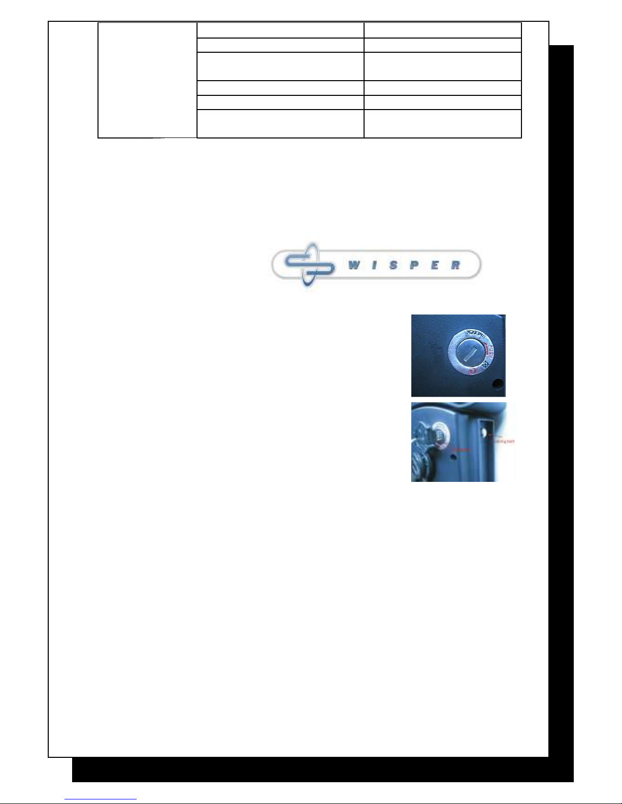
6.7 Disc brake pad wear and replace ent. Re ove the
brake pads and check the for wear. If they have
worn to the point where the caliper piston pin-
positioning hole goes all the way through, then
they need to be replaced.
- 7 -

IMPORTANT braking distances increase on wet or icy roads.
6.8 Lubrication:
Every three onths lubricate the chain with light oil
6.9 Reco ended tools for proper aintenance:
Torque wrench with lb•in or N• gradations 2, 4, 5, 6, 8 Allen
wrenches
9, 10, 15 open-end wrenches 15 box end wrench
Socket wrench, 14, 15, and 19 socket T25 Torx wrench
No. 1 Phillips head screwdriver Bicycle tube patch kit, tire pu p
7 Technical specifications & performance
Type Wisper 906Alpino
Performance (with 75kg 165lb rider)
Assisted range 8A up to 50k
14A up to 70k
8Ah up to 38k
Battery only 14Ah up to 50k
Maxi u speed 25kph (15.5 ph)
Weight with 14Ah battery 26.9kg ax
Maxi u load 130kg (240)
- 8 -

Battery specifications
Cell Type Advanced Environ ental Lithiu Poly er with PCM
Capacity 8Ah or 14Ah
Rated voltage 37V
Main Controller specifications
Low voltage safeguard 31.5V
Overload current safeguard 15A
Main hub motor specifications
Motor type Hi speed brushless
Rated power Aus 200W / NZ Europe 250W / USA Canada 350W
Rated voltage 36V
Charger Lithiu 115 to 230V 36V fan cooled
8 Si ple Trouble shooting
Proble Possible reasons Trouble shooting
Top speed too
slow
1. Low battery voltage
2. Handle bar control proble
3. Da age to otor driveline
1. Recharge battery fully
2. Call service
3. Call service
Power on but
otor not working
1. Battery not connected position
2. Fused
3. Motor connection da aged
4. Handle bar control proble
1. Re install battery
2. Replace fuse
3. Call service
4. Call service
Driving shorter
distance per
recharge
1. Tyre pressure too low
2. Undercharge or charger fault
3. Battery capacity loss or
da age
4. Hill cli bing, frequent stops,
strong head winds, over loading
1. Check pressures
2. Recharge co pletely or
have charger inspected
3. Replace battery
4. Use power assist and try and
avoid throttle only
LCD diagnostics 02 flashes Motor current is too high
03 flashes Motor cable connection ay
- 9 -

be loose.
04 flashes Battery voltage is too low.
05 flashes Brake lever cut out function
proble .
07 flashes The throttle is faulty.
08 flashes Controller faulty
09 flashes Battery output voltage is too
high.
Part 2 Controls and Equipment
In this section we will describe the functions and any specific aintenance needed
on all the ain controls and ancillary equip ent.
9 Battery on off and battery lock
9.1 Your Wisper bike has 1 set key. The key for turns the
battery on/off and locks the battery in the bike.
Please keep a careful note of the key nu bers as we
cannot replace the without these nu bers should
they beco e islaid.
9.2 The battery is connected to the electrical syste of the
bike auto atically when you slide the battery into the
fra e. To turn on the bikes electrical syste , turn the
key in the battery clockwise, to turn off the power
turn the key anti clockwise.
9.3 When the battery has been turned on the bike is now
ready for use. The ON/OFF button on the handle bar display unit isolates
the power fro the bike, when the bike is “on” you will see the LCD display
illu inated. When the ON/OFF button is pushed and the LCD shut down
you have turned the bike “off”. When the bike is “off” you will not get any
assistance fro
the battery and otor and the bike is effectively si ply an unpowered
push bike.
9.4 To lock the battery into the bike fra e turn the key clockwise the locking bolt
holds the fra e, if you want to turn the battery power on, turn clockwise
again, if you want to unlock press the key and turn the key anti clockwise
while the key at lock position. (Refer to the picture) Read 3 and 4 for
battery care and advice on charging at the beginning of this anual.
9.5 The battery can be charged either on or off the bike.
9.6 To re ove the battery turn off the power by turning the key to position
- 10 -

“Unlocking”, raise the seat post to its axi u height. Using the handle
on top of the battery lift out the battery.
9.7 To replace the battery reverse the procedure for re oving it.
10LCD function description
10.1 The LCD display has the following functions (Refer to picture below).
A: Power ON/OFF button. For details refer to the paragraph below.
B: Up (increase) adjusting button. For adjusting the pedal assistance strength,
and back light brightness.
C: Down (decrease) adjusting button.
D: Set. When pressed, you can set the back light of the LCD and the
single trip distance. If you press it together with C button, you can set the
bike’s tyre size.
E: This shows the instant power consu ption extent. A longer bar eans
the otor’s output is higher.
F:
Battery capacity. Three bars indicate 80% capacity left, two bars indicate
70% left, one 55% capacity left, half bar 5% capacity left.
G: Instant speed figures.
H: Pedal assistance strength levels.
I: Total riding distance since last reset.
10.2 When the ON/OFF button is pushed and the capacity indicator goes out
- 11 -

you have turned the bike “off”. When the bike is “off” you will not get any
assistance fro the battery and otor and the bike is effectively si ply an
unpowered push bike. To turn the power back on so the pedelec and
throttle work again si ply press the ON/OFF button once, the capacity
indicator will illu inate showing the power is on.
10.3 How to adjust functions:
10.3.1 How to adjust the pedal assistance. Refer 12.2, 12.3 and 12.4
paragraphs.
10.3.2 How to adjust the back light of the LCD. Press the “set” button
once, you will see a light sy bol added under the battery
capacity indicator, then press the “up arrow” to turn the back light
on. The ore ti es you press the brighter back light you will get.
Refer to above picture.
10.3.3 How to read the single trip distance. Press the “set” button twice;
you will see a sy bol in the left side of the screen.
10.3.4 How to read the single trip riding ti e. Press the “set” button three
ti es; you will see a clock sy bol in the left side of the
screen. This display does not provide the ti e of day – si ply
elapsed riding ti e since last reset.
11The LIGHTS
11.1 The front light is an auto atic sensor light.
When you turn the power on, it checks the
brightness of the surroundings. It will light
when you ride the bike in low light
conditions. It will turn off after 30 seconds
when the a bient light increases.
11.2 The rear light is also auto atic. The sensor
point is fro front light.
12 Pedelec ode and ASSIST
ode
- 12 -

12.1 When you first ride your 906Alpino you will notice that after one turn of
the pedals the otor will start working assisting you ride the bike by
adding power to the front wheel. This is the standard or pedelec ode, to
continue using the pedelec ode you ust keep turning the pedals, if you
stop the otor will stop and the bike will slow to a halt. If you start
pedaling again after one turn the otor will start again.
12.2 You will find the ASSIST level shows on the LCD display. You can adjust the
assistance strength by pressing the up or down arrow. There are 6 levels of
assistance(
40%/50%/60%/70%/90%/100%)
.
12.3 70%, 90% and 100% ode are generally used when you need a greater
a ount of assistance fro the otor. 60% ode is used when you do not
need the instant power of 90% or 100%. 40% and 50% are used in high
traffic situations or poor conditions such as ice and snow when 70%, 90%
and 100% power i ediately could be dangerous.
12.4 Power consu ption. When you increase the assistance, you will find the
battery range is reduced
13Throttle
13.1 The throttle can be used independently to the pedelec ode but the
operation will vary depending on the country where the bike is supplied.
Bikes are set up to be legal in the region in which they are supplied and will
either provide full power (100%) or power up to 4 ph (6kph) (walkalong
ode) independently of the pedelec.
13.2 The independent use of the throttle, when available, will enable you to use
the
throttle without pedaling. However to achieve opti u perfor ance and
life fro the otor it is reco ended that large throttle openings fro
rest be avoided and that where possible pedal assistance should be used
when starting the bike fro rest.
13.3 The use of the throttle in pedelec ode is legal in ost countries. Throttle
in pedelec ode enables you to turn up the power to the otor as long as
you are pedaling the bike, if you stop pedaling the otor will stop too. If
you have the pedelec ode set too Low, you can increase the assistance
fro the otor fro 40% to 100% of available power si ply but turning
the throttle towards you.
IMPORTANT Make sure your throttle grip and the grip on the left hand side of
your
handle bars are always intact, in good condition and on the bike. Uncovered
handlebar
tubes can be very dangerous in case of a collision. Ensure the spacer fitted
between the throttle and the grip is properly installed
- 13 -

14Brakes
14.1 Front: Disc Rear: disc
14.2 The brakes on your Wisper bike are fitted with cut outs which are required
by law. This eans that when you pull on either the back or front brake
lever the otor i ediately stops working.
14.3 Details of how to adjust and aintain your brakes are as follows:
Once a onth, inspect brake pads and blocks for wear. If they have
reached the wear li it then replace the ite s.
Front disc:
Mechanical disc brakes offer several advantages over traditional ri brakes
better braking in wet, uddy or other adverse conditions, less braking
power
fade over extended downhill braking and the ability to continue braking
even if your ri beco es bent or distorted.
14.3.1. Adjust the pads and caliper
14.3.1.1.
Use a 3 Allen wrench to adjust the stationary caliper
adjusting bolt at the back (hub
side)of the caliper. Adjust the
bolt so that there is 0.3
clearance between the stationary
(hub side) pad and the rotor.
14.3.1.2.
Adjust the cable tension to the desired odulation by
tightening/loosing the tension
odulation adjuster bolt on
the caliper with 5 Allen
wrench
14.3.1.3. Adjust the cable adjuster
bolt
on the caliper so that there is
0.3 clearance between the
outside pad and the rotor. Turn
this bolt in a clockwise
- 14 -

direction to provide ore clearance, and anti-clockwise for less
clearance.
14.3.2.
Re oving and installing pads.
Caution: The pads and rotor ust be kept clean and free fro oil or
grease based conta ination. If the pads beco e conta inated you
ust discard the and replace the with a new set. A conta inated
rotor should be cleaned with brake cleaning solvent and dried.
14.3.2.1.
Unscrew caliper’s two screws fixed in front fork. Pads can be
re oved by releasing the pin which goes through the pads and
then anoeuvering the pads out of the rotor slot. Straighten
the pin or replace with a new ite if da aged.
14.3.2.2.
Holding the pad end-tab, insert it into caliper slot with its
etal backing towards the piston. Make sure the hole in the
etal backing goes over the piston pins. When correctly
inserted, the pad will be held in place agnetically, repeat for
the other pad following the reverse procedure.
Rear brakes:
14.3.3. Adjust the pads and caliper
14.3.3.1.
Use a 3 Allen wrench to adjust the
stationary caliper adjusting bolt at the back (hub
side) of the caliper. Adjust the bolt so that there
is 0.3 clearance between the stationary (hub
side) pad and the rotor.
14.3.3.2.
Adjust the cable tension to
the desired odulation by
tightening/loosing the tension
odulation adjuster bolt on
the caliper with 5 Allen
wrench
- 15 -

14.3.3.3.
Use a 3 Allen wrench(Refer to picture) to adjust the left side
caliper’s pad 0.3 clearance between the rotor.
14.3.4. Re oving and installing pads.
14.3.4.1.
Unscrew two caliper screws
fixed in the rear fork. Re ove
the clip(Refer 14.3.3.1 picture),
and then unscew the bolt
shown in the picture. Then
anoeuver the pads out of the
rotor slot.
14.3.4.2. Holding the pad end-tab,
insert it into caliper slot with
its etal backing towards the
piston. Make sure the hole in the etal
backing goes over the piston pins. When correctly inserted, the
pad will be held in place agnetically, repeat the procedure for
the other pad.
Warning: If you are unsure about any part of the installation process
you should seek advice fro Wisper service center or qualified
echanic.
15 Ste handle bar cla p
- 16 -

15.1 Your bike has been fitted with a quick release handlebar cla p that allows
you to change the position of the bars quickly and easily to find the ost
co fortable riding position.
15.2 The ste and handle bars need to be fitted before you use the bike.
15.3 To fit, insert the ste into the front tube at least to the position of the
“Mini u insertion” ark.
15.4 Tighten the quill bolt and fix ste .
14.5 Push in the direction of the arrow slide cap 1 and lift lever 2.
15.6 Adjust ste to preferred angle and lightly tighten BOLT 1 then BOLT 2
to a suitable position so that the slide cap 1 will fit when locked, then press
down lever 2 to lock the handle bars in position.
15.7 Test the bars to ake certain they are tight and do not rotate. If they are
not tight enough, release lever 1, lift lever 2, adjust BOLT 2 again then
press down lever 2. Repeat until the handle bars are tight and safe.
IMPORTANT when fitting always adjust Bolt 1 first so the body and
cap touch then Bolt 2.
16 The front connection box
16.1 The front connection box allows for the easy re oval for repair
or replace ent of any of the electronic co ponents on the
handle bars. Please ensure no wires are trapped between the two
halves when reasse bling and do not over tighten the 4 screws.
17 Quick release saddle height adjust ent
17.1 Your Wisper bike has been fitted with a quick release saddle post collar to
facilitate the ove ent of the saddle to re ove the battery or to change
the riding position. Always ensure the collar is fully engaged on the seat
tube.
17.2 It is i portant that the nut on the collar is tightened so the post will be
gripped in the bike tube fir ly. Make this adjust ent with the quick
release lever in the open position.
17.3 Adjust the seat to the correct height and close the lever. When you sit on
the saddle there should be no vertical ove ent at all in the saddle post.
IMPORTANT never raise the saddle past the point where the maximum marks on
- 17 -

the
saddle post are visible above the quick release collar
18 Ri s and spokes
18.1 It is essential to have your spokes checked and tightened after 300 iles.
This is a free service provided by your supplier. If this service has not been
undertaken at the correct ti e this ay cause da age to the wheels and
spokes that will not covered under our guarantee.
19Chain and drive wheel
20.1 The chain and drive wheel are ade fro rust proof aterials.
20.2 Lightly oil with bicycle chain oil at least once a onth.
20Gear hub
21.1 Your Wisper bike with the pre iu quality 8 speed SHIMANO Alfine gear
box. You can adjust it by the rapid fire shift lever even when the bike is
stationary. Under nor al conditions no aintenance is required.
Warranty
Repair or replacement of components
IMPORTANT To validate this Warranty the retail customer must register the bike at
www.wisperbikes/mywarranty within 14 days of purchase.
Only use this product in accordance with this user manual. We offer a limited warranty of on
the following items.
1 The main frame Si years
2 Gears, bearings, motor shell, hub motor, front forks Two years
3 Handle bar controls, brakes (e cluding brake shoes and pads) One year
4 Controller and Charger Two years
5 Battery casing, battery leak, battery capacity step-down more than 25% Two year
6 Paintwork (e cluding deliberate or accidental damage) Two years
- 18 -

7 Front and rear a le, chain wheel One year
8 Electro plating, on wheel rims, rack and kickstand Si months
9 Other cases that render the bike unsafe to use. By negotiation
1. If the product has a quality fault within 15 days of delivery the part will be repaired or
replaced or in e ceptional circumstances we may replace the whole vehicle.
2. The period of assurance shall commence from the day delivery was made to the retail
customer, or from the day the retail customer collected the bike from the retailer.
3. To validate this Warranty the retail customer must register his / her bike at
www.wisperbikes/mywarranty within 14 days of purchase.
Exceptions to Limited Warranties
1. Damage resulting from misuse, not maintaining the vehicle or not following the guidelines
within this user guide
2. Accidental or deliberate damage
3. Damage due to private repair or alteration by user or unauthorised service centre.
4. Failure to produce invoice or proof of purchase.
5. Spare parts and components worn in normal use.
6. Failure to register your bike at www.wisperbikes/mywarranty within 14 days of purchase.
It is essential to have your spokes checked and tightened after 300 miles. This is a
free service provided by your supplier. If this service has not been undertaken at
the correct time this may cause damage to the wheels and spokes that will not
covered under our guarantee.
ervice through
Your retailer
- 19 -

or
Wisper Ltd
10 Oakenbrow
Sway
Hants
SO41 6DY
Tele:01590 681553
Mobile:07977 185830
douglas.law[email protected]o
www.wisperbikes.co
Copyright January 2010 Wisper Ltd
- 20 -
Other manuals for 906 Alpino
1
Table of contents
Other Wisper Bicycle manuals

Wisper
Wisper 905 ECO User manual

Wisper
Wisper 705se User manual

Wisper
Wisper 705 Classic 2013 User manual

Wisper
Wisper 806 Classic 2013 User manual

Wisper
Wisper 905 ECO User manual

Wisper
Wisper 929 Torque 2016 User manual

Wisper
Wisper 705se User manual

Wisper
Wisper 905se City User manual

Wisper
Wisper 805FE User manual

Wisper
Wisper TAILWIND User manual