Lippert Components HYDRAULIC SLIDEOUT SYSTEM Operation manual
HYDRAULIC SLIDEOUT SYSTEM
OPERATION AND SERVICE MANUAL

TABLE OF CONTENTS
SYSTEM……………………………………………........….…..
Warning…………………………………........……....
Description………………………………........……..
Prior to Operation…………………….......………
Preventative Maintenance……….......………..
OPERATION…………………………………........……………
Warning.........................................................
Extending Slideout Room….............………….
Retracting Slideout Room…….............……...
Auxiliary Operation....…………............……….
SERVICE…………………………..………………........………
Filling Procedures........................................
Adjustment Instructions……….......…………..
Syncronizing System...................................
Replacing Actuator......................................
Troubleshooting…………………….........………
Wiring Diagram…………………….….......………
LIMITED WARRANTY………………......……....………….
Warranty Registration.................................
3
3
3
3
4
5
5
5
5
6
7
7
7
9
10
11
13
14
16
2

SYSTEM
WARNING
FAILURE TO ACT IN ACCORDANCE WITH THE FOLLOWING MAY
RESULT IN SERIOUS PERSONAL INJURY OR DEATH.
The Lippert Hydraulic Slideout System is intended for the sole
purpose of extending and retracting the slideout room. Its
function should not be used for any other purpose or reason than
to actuate the slideout room. To use the system for any reason
other than what it is designed for may result in damage to the
coach and/or cause serious injury or even death.
Before actuating the system, please keep these things in mind:
1. Parking locations should be clear of obstructions that may
cause damage when the slideout room is actuated.
2. Be sure all persons are clear of the coach prior to the
slideout room actuation.
3. Keep hands and other body parts away from slideout
mechanisms during actuation. Severe injury or death may
result.
4. To optimize slideout actuation, park coach on solid and level
ground.
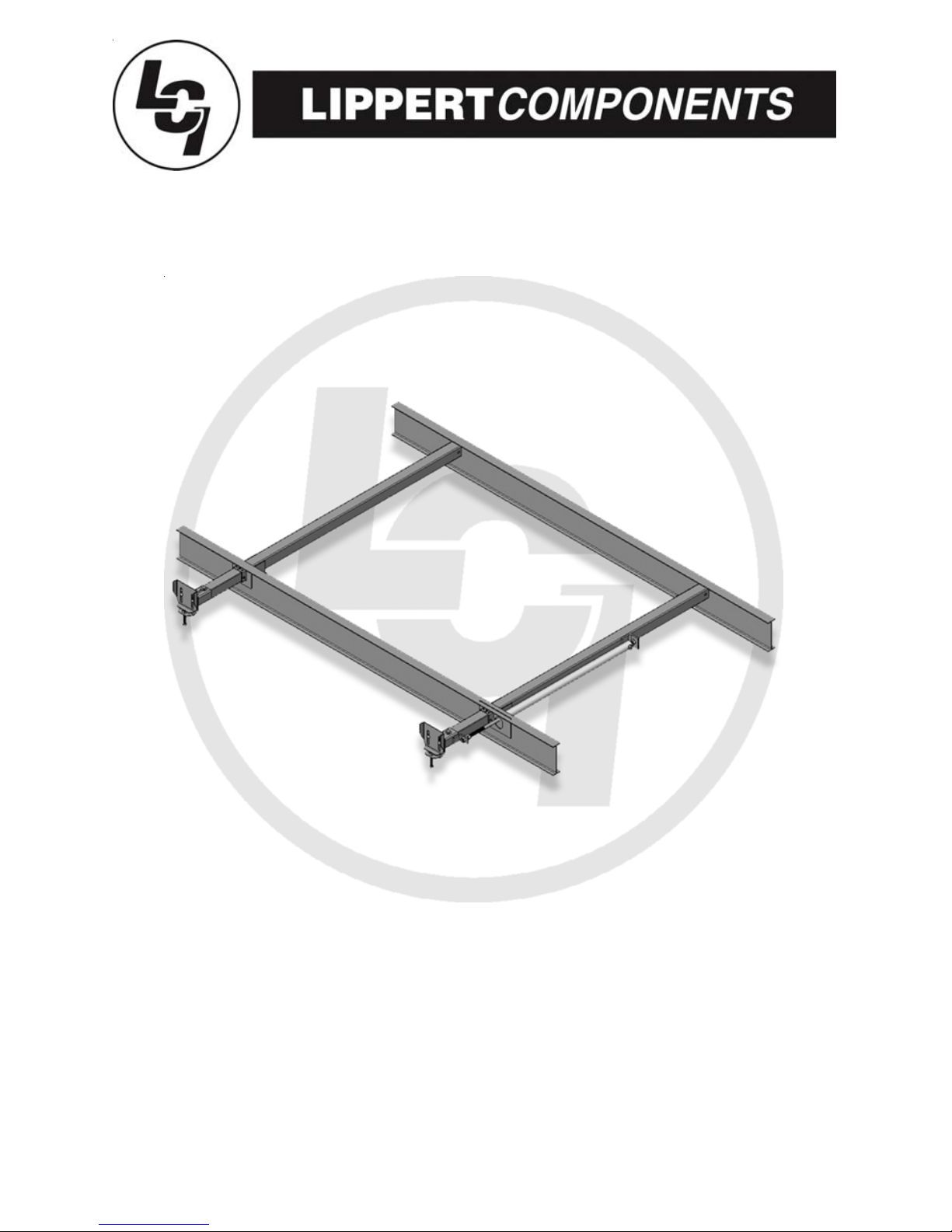
DESCRIPTION
The Lippert Hydraulic Slideout System is a rack & pinion guide system, utilizing a
hydraulic actuator to move the room assembly. The power unite drives the
cylinder rod in a forward and backward motion to drive the slide room in and out.
The Lippert Hydraulic Slideout System is designed to operate as a negative
ground system.
3
PRIOR TO OPERATION
Prior to operating the Lippert Hydraulic Slideout System, follow these guidelines:
1. Coach should be parked on the most level surface available.
2. Leveling or stabilizing system should be actuated to ensure coach will not
move during operation of Bed Lift System.
3. Be sure battery is fully charged.
4. Be sure to keep all persons and pets clear of Bed Lift System during
operation.

SYSTEM MAINTENANCE
The Lippert Hydraulic Slideout System has been static tested to over 4,000
continuous cycles with out any noticeable wear to rotating or sliding parts. It is
recommended that when operating in harsh environments (road salt, ice build
up, etc.) the moving parts be kept clean and can be washed with mild soap and
water. No grease or lubrication is necessary and in some situations may be
detrimental to the environment and long term dependability of the system.
Electrical System Maintenance
For optimum performance, the slide-out system requires full battery current and
voltage. The battery must be maintained at full capacity. Other than good battery
maintenance, check the terminals and other connections at the battery, the
control switch, and the electric actuator motor for corrosion, and loose or
damaged terminals. Check motor leads under the trailer chassis. Since these
connections are subject to damage from road debris, be sure they are in good
condition.
NOTE: The Lippert Hydraulic Slideout System is designed to operate as a
negative ground system. A negative ground system utilizes the chassis frame as
a ground and an independent ground wire back to battery is necessary (see
page 19 for wiring diagram). It is important that the electrical components have
good wire to chassis contact. Over 90% of unit electrical problems are due to
bad ground connections.
Mechanical Maintenance
Although the system is designed to be almost maintenance free, actuate the
room once or twice a month to keep the seals and internal moving parts
lubricated.
Check for any visible signs of external damage after and before movement of the
travel trailer.
NOTE: For long-term storage: It is recommend that the room be closed
(retracted).
4

OPERATION
WARNING
FAILURE TO ACT INACCORDANCE WITH THE FOLLOWING MAY
RESULT IN SERIOUS PERSONAL INJURY OR DEATH.
ALWAYS MAKE SURE THAT THE SLIDEOUT ROOM PATH IS CLEAR OF
PEOPLE AND OBJECTS BEFORE AND DURING OPERATION OF THE
SLIDEOUT ROOM.
ALWAYS KEEP AWAY FROM THE SLIDE RAILS WHEN THE ROOM IS BEING
OPERATED. THE GEARASSEMBLY MAY PINCH OR CATCH ON LOOSE
CLOTHING CAUSING PERSONAL INJURY.
INSTALL TRANSIT BARS (IF SO EQUIPPED) ON THE SLIDEOUT ROOM
DURING STORAGE AND TRANSPORTATION.
EXTENDING SLIDEOUT ROOM
1. Level the unit.
2. Verify the battery is fully charged and hooked-up to the electrical system.
3. Remove the transit bars (if so equipped).
4. Press and hold the IN/OUT switch (Fig. 1B) in the OUT position until the
room is fully extended and stops moving.
5. Release the switch, which will lock the room into position.
NOTE: If the slideout switch is held after the room in fully extended, the control
will sense that the room has stopped and will shut off the motor after a few
seconds.
RETRACTING SLIDEOUT ROOM
1. Verify the battery is fully charged and hooked-up to the electrical system.
2. Press and hold the IN/OUT switch (Fig. 1C) in the IN position until the room
is fully retracted and stops moving.
3. Release the switch, which will lock the room into position. NOTE: If the
slideout switch is held after the room in fully retracted, the control will sense
that the room has stopped and will shut off the motor after a few seconds.
4. Install the transit bars (if so equipped).
5
Fig.1
C
B
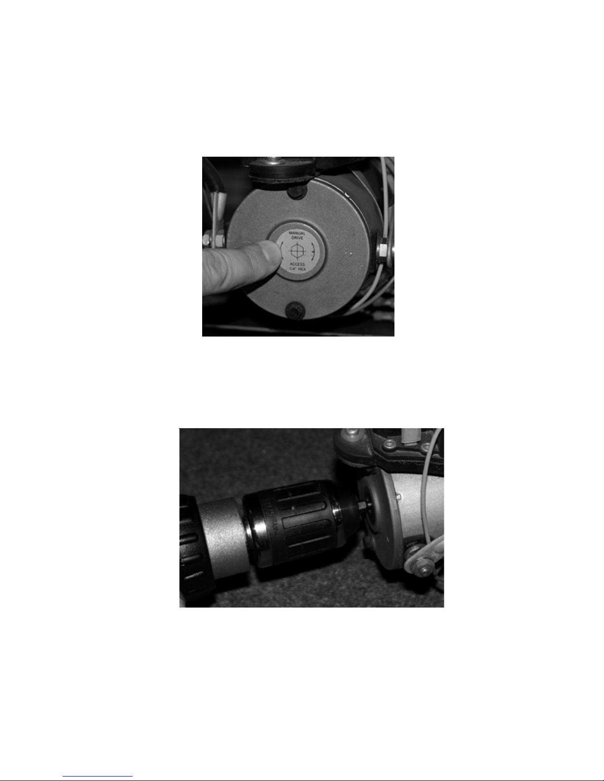
3. Insert hex bit into coupler found under protective label. (See Fig. 3)
4. Run drill forward or clockwise to extend slideout room and in reverse or
counterclockwise to retract slideout room.
Fig. 3
1. Remove protective label. (See Fig. 2).
2. Using a standard hex bit, insert into auxiliary drive device, i.e. cordless drill or
screwdriver or ratchet wrench.
AUXILIARY OPERATION
The Lippert Hydro-Sync Slideout System can be run with auxiliary power devices
like electric drills, ratchet wrenches or cordless screwdrivers. In the event of
electrical or system failure, this manual method of extending and retracting the
slideout room can be used. Astandard handheld drill is all that is required. A
standard 38" room will take approximately 45 seconds to retract. See the
instructions below.
6
Fig. 2

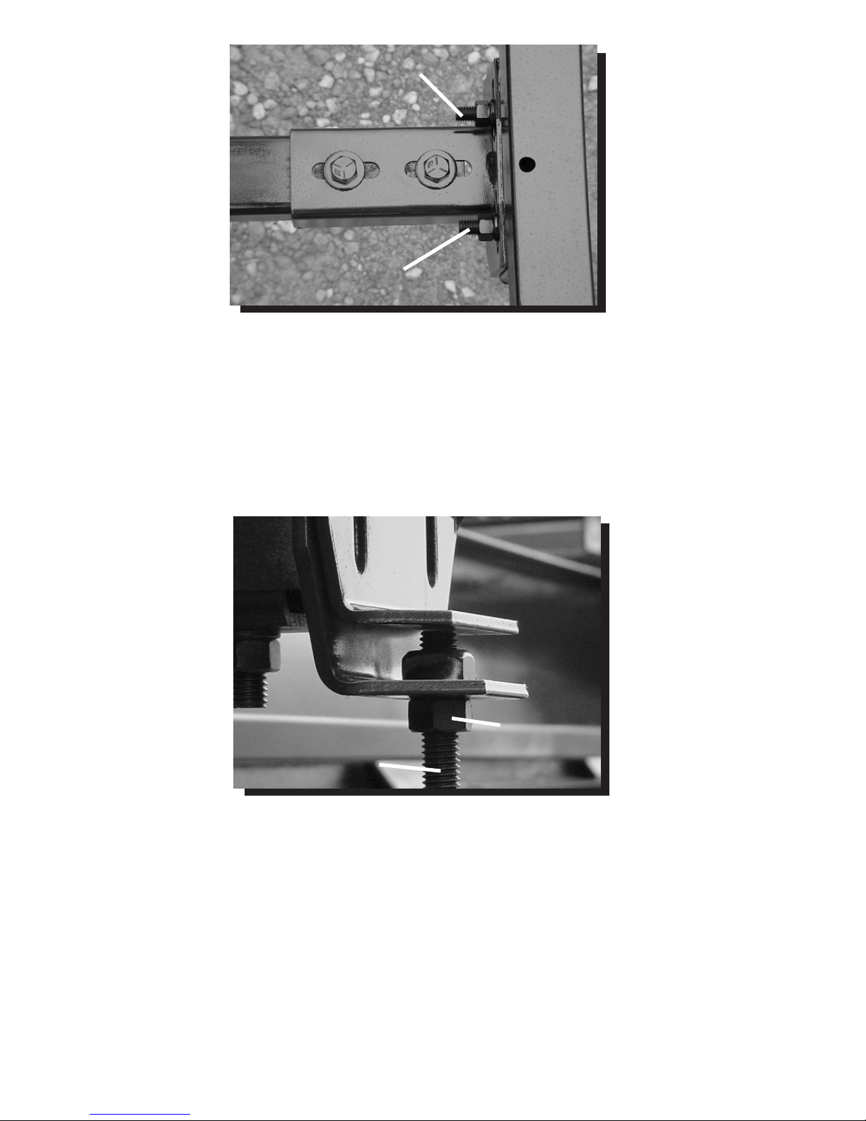
MECHANICAL ROOM ADJUSTMENT
Vertical & Horizontal Room Adjustment
NOTE: All slideout room adjustments must be performed by certified service
technicians. Adjustments made by non-certified persons may void any and all
warranty claims.
Horizontal adjustment
1. Loosen 2 carriage bolts “A” on each bracket located at the end of
each guide tube.
2. Room is ready to be positioned horizontally by pushing on the
outside, sidewall or by using a prying devise inserted into the
opening between the room and coach.
FLUID FILLING PROCEDURE
The Lippert Hydraulic Slideout System uses automatic transmission fluid (ATF).
AnyATF can be used. A full synthetic or synthetic blend works best such as
Dexron III or Mercon 5. For best operation, fill system within ½” of the top when
all slideouts are completely retracted. The see through reservoir makes it easy
to check oil level. It is recommended that the oil level be checked prior to
operating the system. Make sure the breather cap is free of contamination
before removing, replacing or installing.
FILLING DIRECTIONS
Remove Breather/Fill Cap
PourATF into Breather/Fill opening.
NOTE: Do not allow any contamination into reservoir during fill process.
NOTE: Standard reservoir holds approximately 2 quarts (1.89 liters) of
ATF.
Fill to within ½” of top.
Replace Breather/Fill cap when finished.
NOTE: System is self-purging. By simply cycling the system 2-3 times,
any air in the system will be forced back to the reservoir and out of
the Breather/Fill cap.
7
Breather Cap
Fig. 4
8
NOTE: Use caution when using prying devise so seals do not become damaged.
Vertical adjustment
1. Loosen 2 carriage bolts “A” on each bracket located at the end of
each guide tube
2. Loosen jam nut
3. For vertical adjustment turn vertical adjustment bolt “B” up or
down to locate room height.
Once room is located, tighten “A” and Jam Nut bolts.
Fig.5 Bolt “A”
Bolt “A”
Bolt “B” Jam Nut
Fig. 6
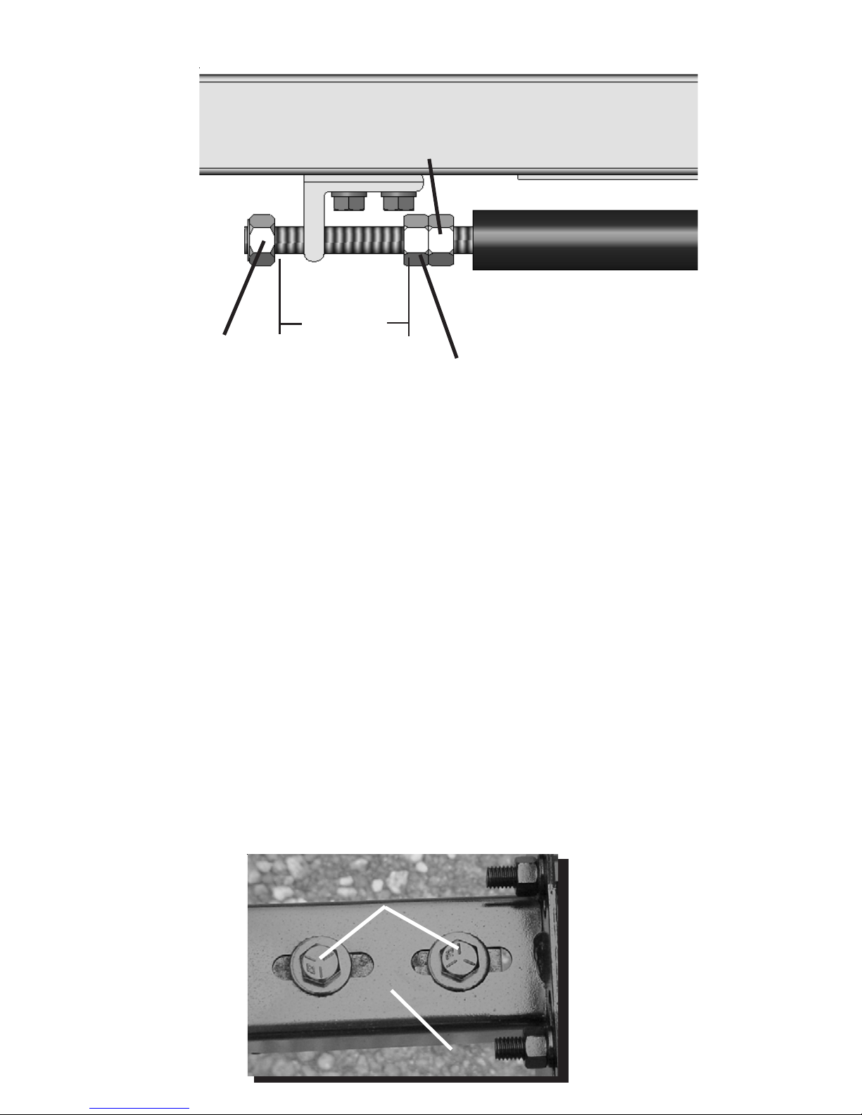
SYNCHRONIZING ROOM TRAVEL
Fig. 9 A
B
MECHANICAL ROOM ADJUSTMENT-CONT.
Adjusting room so it seals in the IN position
1. Locate cylinder coming through the frame;
2. On the end of the cylinder there is a threaded shaft mounted to the
drive bracket with 3 nuts.
3. Loosen the Jam Nut-1 and set Jam Nut-2 to desired location.
4. Tighten down the Nylock Nut against bracket. Make sure Jam Nut-2
is adjusted for “FREE TRAVEL” (see above). Secure assembly by
tightening Jam Nut-1against Jam Nut-2. This will change the
location of your seal going to the “in position”.
Adjusting room so it seals in the OUT position
1. Locate actuator coming through the frame;
2. On the end of the cylinder there is a threaded shaft mounted to the
bracket with 3 nuts.
3. Adjust Jam Nuts 1 & 2 one way or the other– this will change the
location of your seal going to the “outposition”.
4. Make sure all nuts are tight.
Jam Nut-1
Jam Nut-2
Nylock Nut
2” - 3”
FREE TRAVEL
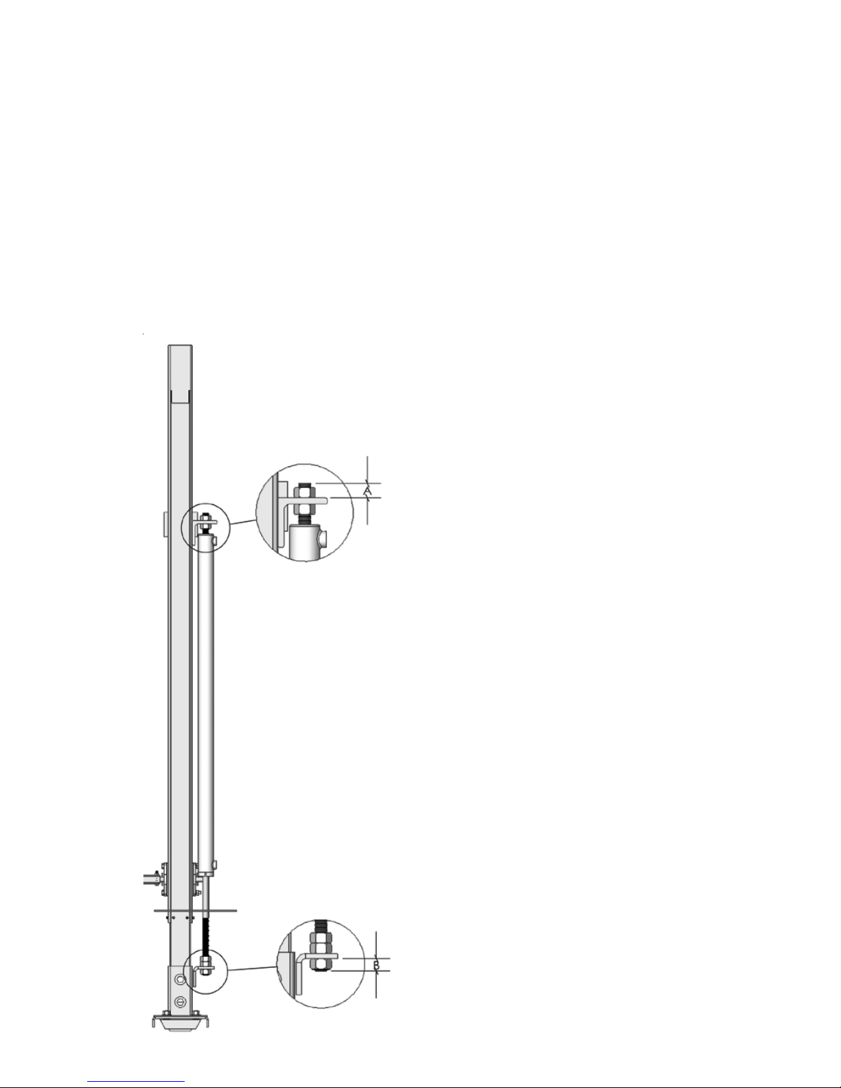
To replace actuator:
1. Take measurementsA and B.
2. Remove both nylock nuts (2 total) from
threaded shafts on actuator.
3. Take note of jam nut locations and remove.
4. After everything is disconnected, slide
actuator out of frame. To replace with new
actuator, follow previous directions in
reverse.
REMOVING AND REPLACING ACTUATOR
Fig. 10
10
The Lippert Electric Slideout System room travel (both sides of the room
traveling the same distance) can be adjusted with specially designed
synchronizing bracket mounted on the passive slide tube. The passive slide tube
is the one that is not powered. The active slide tube is the one that has the
cylinder attached. If one side of the room fails to seal adjust as follows:
1. Loosen bolts (Fig. 9A) on top of the passive slide tube (Fig. 9B)
2. Push or pull room (on the passive side) to align with the active side.

TROUBLESHOOTING CHART
The following troubleshooting chart outlines some common problems, their causes and possible
corrective actions. When reference is made to a “Power Unit,” the term includes the motor and
the actuator as a complete unit. All Power Units are shipped from the factory with a serial number
and date code, which should be given to the service technician when asking for assistance.
11
ROOM DOESN’T MOVE WHEN SWITCH IS PRESSED
PROBABLE CAUSE CORRECTIVE ACTION
Restrictions both inside and outside of unit Check for and clear restriction
Low battery voltage, blown fuse, defective wiring Check battery. Charge battery or add auxiliary
power source. Check battery terminals, and all
other wiring. Look for loose or corroded connections
Power Unit not functioning See “Power Unit Troubleshooting” page 20
Hydraulic Slideout Manual online at www.lci1.com
POWER UNIT RUNS, ROOM DOES NOT MOVE
Restrictions both inside and outside of unit Check for and clear restriction
POWER UNIT RUNS, ROOM MOVES SLOWLY
Low battery, poorground,extremely low Charge battery, and check ground wire
outdoor temperature.
Leaking cylinder See “Checking for Bad Cylinder” page 12
ROOM DRIFTS IN BOTH IN & OUT POSITIONS
Check for leaks in the hydraulic system Tighten fittings
Air in system After checking all connections, cycle pump
several times in and out
IN THE CLOSED POSITION, ROOM DRIFTS OUT
Leaking cylinder seal See “Checking for Bad Cylinder” page 12
Fluid bypassing cylinderpiston See “Checking for Bad Cylinder” page 12
Hose from pump is leaking Tighten fitting or replace hose
Air in system After checking all connections, cycle pump
several times in and out
Loose mounting bolts Tighten mounting bolts
IN THE OPEN POSITION, ROOM DRIFTS IN
Hose from pump is leaking Tighten fitting or replace hose
Leaking cylinder seal See “Checking for Bad Cylinder” page 12
Fluid bypassing cylinderpiston See “Checking for Bad Cylinder” page 12

TROUBLESHOOTING – CHECKING FOR BAD CYLINDER
1. Retract (close) the slideout (room) completely.
2. Loosen hose from “E” (extend) port on the manifold of the Power Unit.
WARNING- Do not attempt to run room out with the “E” port hose loose. The
system will experience RAPID FLUID LOSS.
3. Plug opening on manifold to prevent drawing air into the system.
4. Energize the Power Unit to retract (close) room.
5. Continue to run the room in and watch for fluid flow from hose/port
“E”. Fluid flow greater than a few drops will indicate internal cylinder
leaking (bypassing of piston seal). If there is no fluid flow, reconnect
hose to “E” port and tighten.
WARNING - Be sure to reconnect and tighten hose at the “E” port before
attempting to extend (open) the room or the system will experience RAPID
FLUID LOSS.
Contact qualified technician if there is excessive fluid flow. The cylinder should
not be repaired in the field.
Refill the Power Unit Reservoir as recommended on Page 10 of this manual.
12
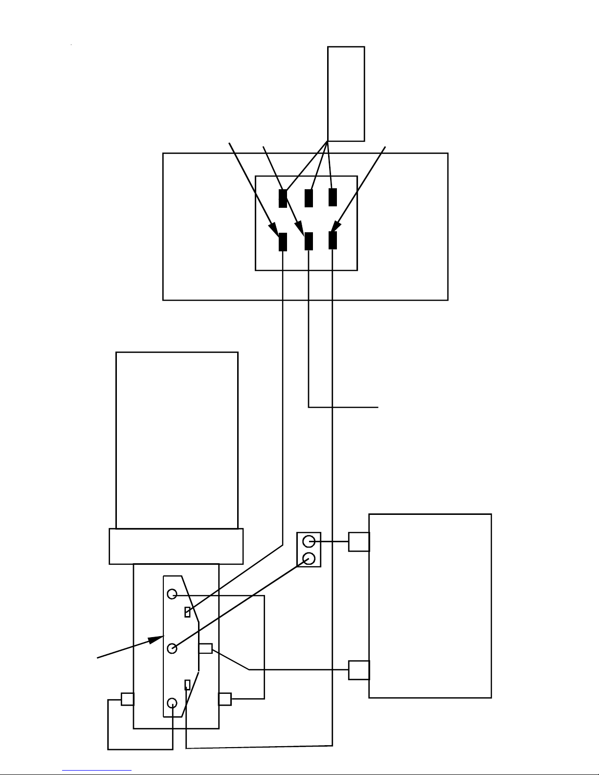
IN
OUT
MOTOR
TROMBETA
SWITCH – Wall
switch and pump
switch get wired
the same way
Yellow
Red “Hot”
Green
BATTERY
- +
No wires connected
to this side of switch
CHANGE OF POLARITY
REVERSES MOTOR
MANIFOLD
RESERVOIR
RV MANUFACTURER
SUPPLIED-
BREAKER
CUSTOMER’S CHOICE
CUSTOMER TO INSTALL APPROPRIATE
WIRE GAUGE AND FUSE FOR 2A DRAW
12VDC SOURCE
WIRING DIAGRAM
Fig. 11
Table of contents
Other Lippert Components Motorhome manuals

Lippert Components
Lippert Components ABOVE FLOOR SLIDEOUT SYSTEM Operation manual

Lippert Components
Lippert Components ELECTRIC SLIDEOUT SYSTEM Operation manual

Lippert Components
Lippert Components Power Gear SlimRack Slide-out Manual

Lippert Components
Lippert Components Solera Installation instructions
Popular Motorhome manuals by other brands


Winnebago
Winnebago 2005 Minnie Winnie owner's manual
Fleetwood
Fleetwood TIOGA ARROW 1986 manual

Holiday
Holiday Vacationer Diesel 2006 owner's manual

Truma
Truma Mover SE R Operating and installation instructions

Pleasure-Way
Pleasure-Way PLATEAU TS 2022 owner's manual

Airstream
Airstream Overlander Twin 1996 user manual