Lippert KWIKEE User manual

Rev: 10.04.18 Page 1 CCD-0002274
TI-284
KWIKEE®DOOR SWITCH STEP ACTIVATION
INSTALLATION GUIDE (1421330)
STEPS
Purpose
NOTE: Information for this document has been obtained from Kwikee® Products document number
1421330, Revision 0B, dated February 2008 and updated for current practices.
This document explains the removal of an existing door switch and installation of a replacement door switch
that will activate the Kwikee electric step when the door is opened and closed. A brief guide to replacement
parts is also included.
Moving parts can pinch, crush or cut. Keep fingers, arms, and legs clear of the step mechanism while
performing these tasks. Failure to do so may result in personal injury. Keep clear and use caution.
If the vehicle is driven with the step in the extended position, there is the possibility of causing major
damage to both the step and the unit. Always make sure that the step is fully retracted before traveling.
Step safely supports up to 300 lbs. DO NOT overload the step assembly. Stepping on a partially extended
step can cause damage to the step frame. Continue pressing door switch until control unit shuts motor
off.
Resources Required
• Two people • Wire crimper or similar crimping tool
• Ruler or tape measure • Heat shrink butt connector
• Pencil • Heat shrink gun
• Screwdriver or cordless or electric drill • Ring terminal
• Appropriate drill bits • Self-tapping screws
• Utility knife or plastic scraper • Silicone rubber sealant
• Wire stripper/cutter or similar tool

Rev: 10.04.18 Page 2 CCD-0002274
TI-284
KWIKEE®DOOR SWITCH STEP ACTIVATION
INSTALLATION GUIDE (1421330)
STEPS
Door Switch Installation
Lippert Components, Inc. (LCI) recommends that the switch be installed on the latch side of the door.
However, hinge-side installation is acceptable. Some experimentation with the switch position may be
necessary to achieve proper step operation. The Kwikee Step assembly should begin to extend when the
door is opened between one and four inches.
Removing Existing Switch
NOTE: No hardware is sold with a replacement door switch kit. Make sure to save existing hardware (i.e.
screws) for re-use. Use the double-sided adhesive tape that comes attached to the standard new
door switch for a temporary hold.
1. Remove the magnet contact from the screen door first.
A. Use a screwdriver or a cordless or electric drill with appropriate drill bits to remove the two screws
holding the magnet in place.
NOTE: Keep the two screws for use when installing the new magnet (Fig. 1).
B. If present, remove any remaining adhesive residue from the surface of the screen door. Use a
utility knife or plastic scraper to remove the residue as needed.
2. Remove the switch from the door frame.
A. Use a screwdriver or a cordless or electric drill with appropriate drill bits to remove the two screws
holding the switch in place.
NOTE: Keep the two screws for use when installing the new switch (Fig. 1).
B. If present, remove any remaining adhesive residue from the surface of the door frame. Use a utility
knife or plastic scraper to remove the residue as needed.
3. Disconnect the ground wire and the wire connected to the control box.
A. Follow the wires from the switch to the underside of the vehicle.
I. The ground wire will be attached to the vehicle with a ring terminal and self-tapping screw.
II. The other wire will be connected to the wire harness that connects to the control box that
operates the step.
B. Pull the existing wires down through the hole in the door frame to the underside of the vehicle.
C. To disconnect the ground, remove the screw holding the ring terminal and ground wire to the
vehicle.
D. Using wire cutters or similar tool, cut the brown wire to the switch at the 4-way connector just
behind the butt connector.
E. Strip back the wire connected to the 4-way connector approximately ½" and attach a heat shrink
butt connector.

Rev: 10.04.18 Page 3 CCD-0002274
TI-284
KWIKEE®DOOR SWITCH STEP ACTIVATION
INSTALLATION GUIDE (1421330)
STEPS
TI-284
KWIKEE®DOOR SWITCH STEP ACTIVATION
INSTALLATION GUIDE (1421330)
STEPS
Reconnecting Wires
1. Feed both new switch wires down through the existing hole in the door frame to the underside of the
vehicle.
2. Pull excess wires through the hole leaving enough wire to attach the switch to the door frame.
3. Insert the end of the longer wire leading from the switch into the open end of the heat shrink butt
connector attached to the 4-way connector to the control box.
4. Secure the butt connector into place using a wire crimper or similar tool.
5. To create a new ground connection, strip back the the insulation on the shorter wire leading from the
switch, then fold the wire a few times to make it fit snug into the ring terminal.
6. Secure the ring terminal into place using a wire crimper or similar tool.
7. Attach the ground wire ring terminal to the vehicle using a cordless or electric drill, appropriate drill bit
and self-tapping screw.
Installing the New Switch
After wiring is complete, install the new switch and magnet.
NOTE: Vertical placement of the magnet is critical to proper door switch operation. There must be a
minimum of six inches from the bottom of the door to the bottom edge of the magnet. The magnet
on the door must be aligned with the switch on the door frame. See figure 1.
Door
Door
Black
Large magnetic
reed switch
Black
Small magnetic
reed switch
Black
Round magnetic
switch
Magnet
Switch
Switch
Upper
floor level
Door
Magnet
6"
minimum
Fig. 1

Rev: 10.04.18 Page 4 CCD-0002274
TI-284
KWIKEE®DOOR SWITCH STEP ACTIVATION
INSTALLATION GUIDE (1421330)
STEPS
NOTE: Under no circumstances should the door switch be forced into its mounting position.
NOTE: Before installing screws in the door switch to securely attach to the unit, perform a quick test to
make sure step is functioning properly.
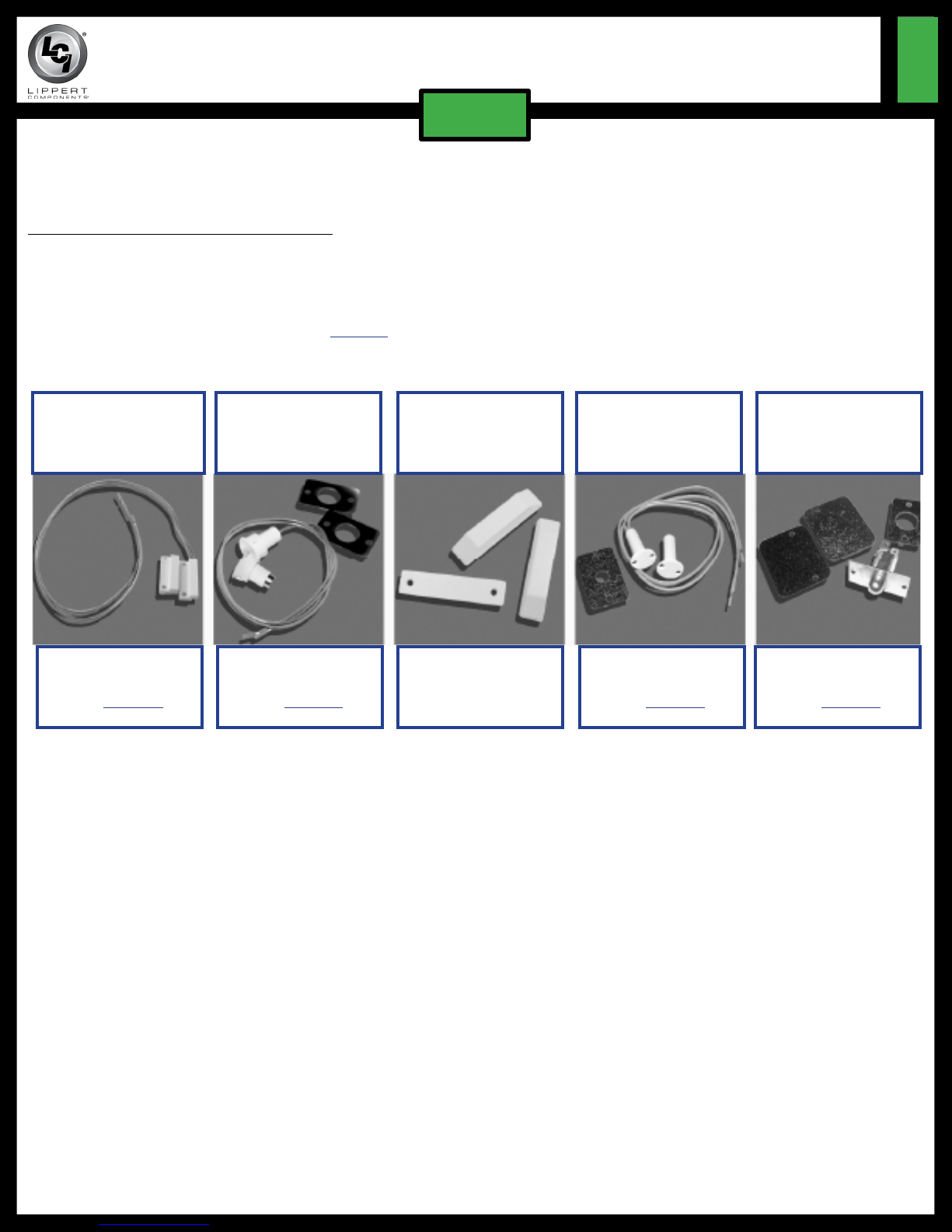
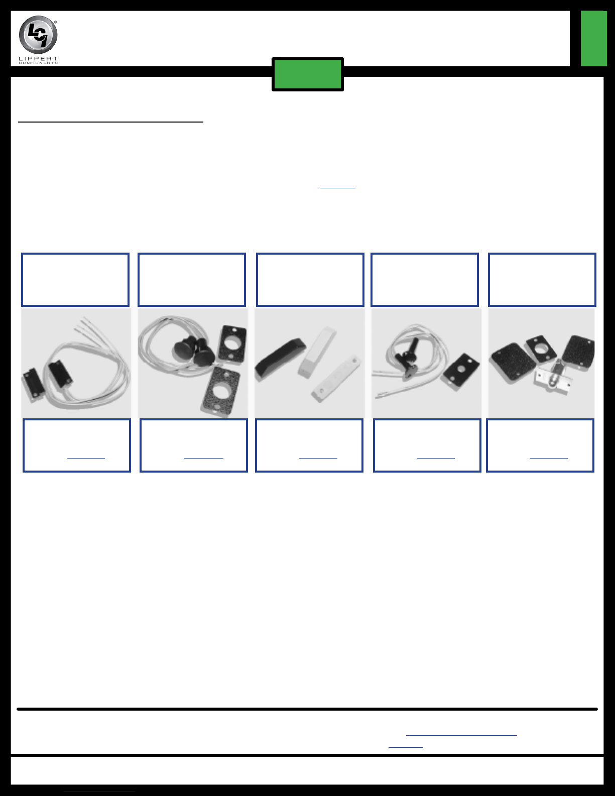
1. Installing the new switch on the door frame.
A. Check for ample clearance in the door frame for the body of the door switch.
B. Remove backing from the double-sided adhesive tape on the back of the switch.
C. Using the double-sided tape, attach the switch to the door frame. The switch can be placed in
the same location as the old switch if the bottom placement of the new switch will be at least six
inches from the bottom of the door frame (Fig. 1).
2. Installing the new magnet on the screen door.
A. Using double-sided tape attached to the magnet, install the magnet on the screen door, opposite
the switch.
B. Make sure to align the magnet with the switch attached to door frame (Fig. 1).
Moving parts can pinch, crush or cut. Keep ngers, arms, and legs clear of the step mechanism while
performing this check. Failure to do so may result in personal injury. Keep clear and use caution.
3. Check switch function to make sure the steps are working properly.
A. Open screen door.
B. Step assembly should extend.
C. Close screen door.
D. Step assembly should retract.
Securing Connections
1. Once the locations of the switch and magnet are correctly set, and steps are working properly, finish
securing the door switch.
A. Line up the holes in the switch and magnet with the holes in the screen door and door frame.
B. Secure using self-tapping screws with a screwdriver or a cordless or electric drill with appropriate
drill bit.
C. If possible, use the same screws previously removed from the old door switch.
2. Under the unit, at the 4-way connector to the control box, use a heat gun to shrink the heat shrink butt
connector attaching the switch to the control box. This will help keep out moisture.
3. In addition, black electrical tape can also be wrapped around the butt connector to keep out dust, dirt,
debris and moisture.
4. Place silicone rubber sealant under the vehicle at the hole where the wires feed to the switch. This will
help seal against moisture or water leaks.

Rev: 10.04.18 Page 5 CCD-0002274
TI-284
KWIKEE®DOOR SWITCH STEP ACTIVATION
INSTALLATION GUIDE (1421330)
STEPS
TI-284
KWIKEE®DOOR SWITCH STEP ACTIVATION
INSTALLATION GUIDE (1421330)
STEPS
IMGL Control
(2006 and newer)
Pre-IMGL Control
(Before 2006)
Troubleshooting
The Kwikee Step assembly should begin to extend when the door is opened between one and four inches.
The step assembly should retract when the door is closed.
If, after installation of a new switch, the step does not operate properly, do as follows:
1. Check to make sure that there are no obstructions in the path of the step assembly preventing its
operation.
2. Check to make sure that all wiring connections are tight and secure.
Replacement Parts—General Information
There are three types of door switches available:
• Rectangular switch (small and large sizes)
• Round switch (¾" or ⁄" core)
• Plated plunger switch.
The replacement procedures outlined in this document apply to door switches used with any Kwikee
control unit - both the latest IMGL (integrated motor/gear box/ linkage) version (Kwikee 909510000 / LCI
379146) used on 2006 or newer models (Fig. 2) and earlier version control units (Fig. 3).
When selecting a replacement door switch from the enclosed guide, make sure to select one based on the
type of control unit that is present.
• For most older units using the pre-IMGL control unit (Fig. 3), select one of the white (normally closed) door
switch options. (Exceptions are noted in the Replacement Parts Guide section.)
• For units with the current IMGL control unit (Fig. 2), select one of the black (normally open) door switch
options. The IMGL-type control unit operates properly with any of the “Normally Open” switches. The IMGL-
type control unit will not operate properly with the white “Normally Closed” switches, the step will operate
backwards.
NOTE: No hardware is sold with a replacement door switch kit. Make sure to save existing hardware (i.e.
screws) for re-use. Use the double-sided adhesive tape that comes attached to the standard new
door switches for a temporary hold.
Fig. 2 Fig. 3

Rev: 10.04.18 Page 6 CCD-0002274
TI-284
KWIKEE®DOOR SWITCH STEP ACTIVATION
INSTALLATION GUIDE (1421330)
STEPS
Magnetic
Small
Rectangular
Kwikee 905312000
LCI 374198
Magnetic
¾" Core
Round
Kwikee 905314000
LCI 379400
Magnetic
Large
Rectangular
Kwikee 905306000
LCI 378043
Magnetic
⁄" Core
Round
Kwikee 905307000
LCI 378047
Plated
Plunger
Switch
Kwikee 905302000
LCI 379388
Replacement Parts Guide
White (Normally Closed) Switches
White, normally closed, switches are used for all non-IMGL control units manufactured prior to February
1999.
NOTE: Exceptions are non-IMGL, black-colored control units Kwikee 909506000 (obsolete, replaced
by Kwikee 909510003 / LCI 379606) and Kwikee 909507000 / LCI 381044 which must use black,
normally open, switches.

Rev: 10.04.18 Page 7 CCD-0002274
TI-284
KWIKEE®DOOR SWITCH STEP ACTIVATION
INSTALLATION GUIDE (1421330)
STEPS
TI-284
KWIKEE®DOOR SWITCH STEP ACTIVATION
INSTALLATION GUIDE (1421330)
STEPS
Kwikee 905323000
LCI 369299
Magnetic
Small
Rectangular
Kwikee 905324000
LCI 378054
Magnetic
¾" Core
Round
Kwikee 905326000
LCI 379406
Magnetic
Large
Rectangular
Kwikee 905327000
LCI 375385
Magnetic
⁄" Core
Round
Kwikee 905328000
LCI 379407
Plated
Plunger
Switch
Black (Normally Open) Switches
Black, normally open, switches are used for all black-colored (IMGL) control units manufactured since February
1999.
NOTE: Also included are the following non-IMGL Kwikee control units manufactured prior to February 1999:
909506000 (obsolete, replaced by 909510003 / LCI 379606), 909507000 / LCI 381044 and 909508000 / LCI
381039.
As a supplier of components to the RV industry, safety, education and customer satisfaction are our primary concerns. Should you
have any questions, please do not hesitate to contact us at (574) 537-8900 or by email at [email protected]. Self-help tips,
technical documents, product videos and a training class schedule are available at lci1.com or by downloading the MyLCI app.
Table of contents
Popular Switch manuals by other brands

SilverStone
SilverStone EP01 manual

Matrix Switch Corporation
Matrix Switch Corporation MSC-5-3248 product manual

Waters Network Systems
Waters Network Systems PSX1008-GTX operating manual

Weidmüller
Weidmüller IE-SW-EL10-8GT-2GESFP Hardware installation guide

IMC Networks
IMC Networks iMcV-T1 specification

SECO-LARM
SECO-LARM Enforcer Relay Module SR-2224-C5 Specification sheet