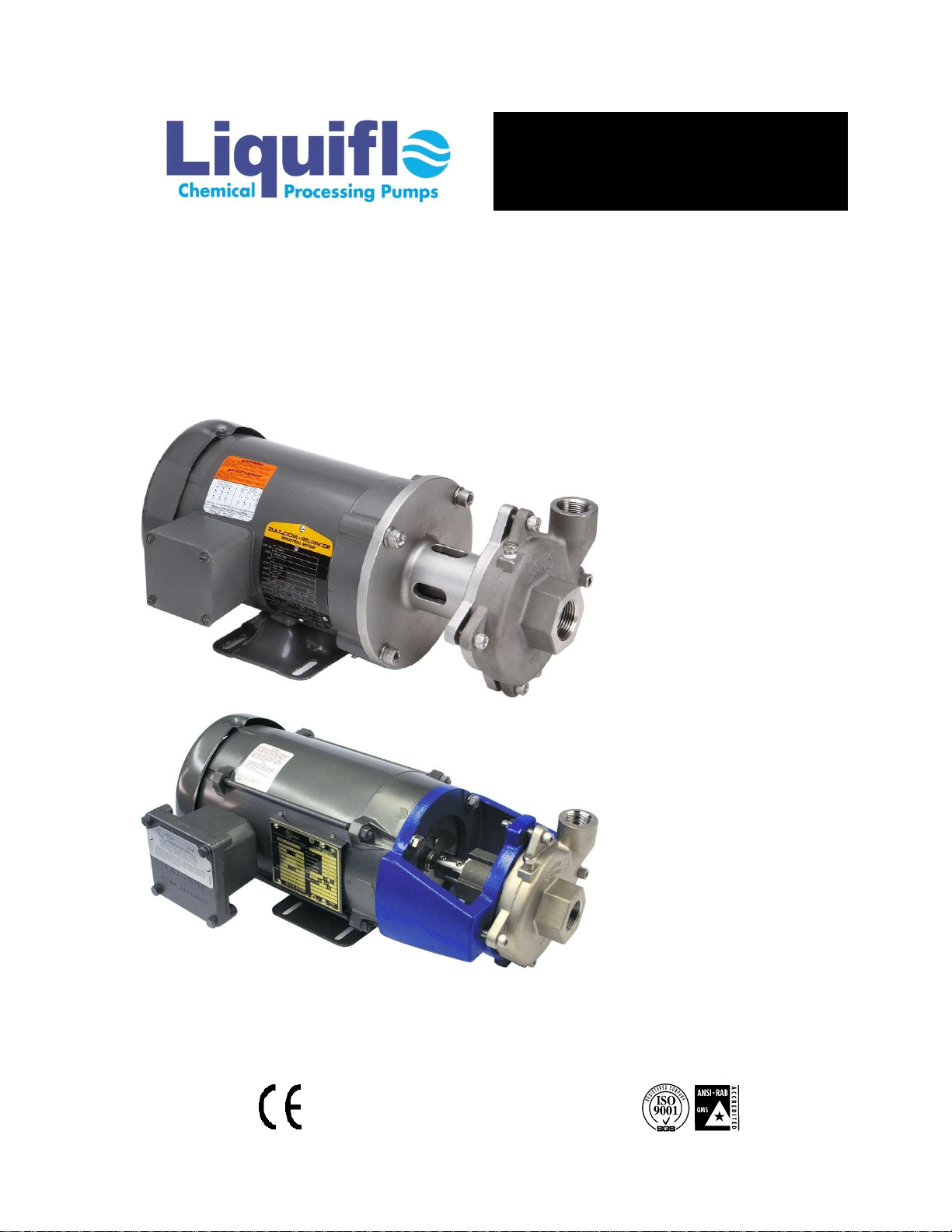
Liquiflo CENTRY 620 Series Instruction manual
INSTALLATION, OPERATION
& MAINTENANCE MANUAL
CENTRY®SERIES
SEALED, CLOSE-COUPLED
CENTRIFUGAL PUMPS
Model 620 –Sealed
© Aug. 2021 Liquiflo, All rights reserved Document No.: 3.20.023
443 North Avenue, Garwood, NJ 07027 USA Tel: 908-518-0777 Fax: 908-518-1847 www.liquiflo.com
TM
New Design:
Closed-Bracket with
Integral Seal Housing
& Type 21 or Type 9T
Single Mechanical Seal
Legacy Design:
Open-Bracket with
Single (Type 9A) or
Double Mechanical
Seal, or Packing

Liquiflo Installation, Operation & Maintenance Manual Centry®Series Centrifugal Pumps
Model 620 –Sealed
2
Introduction
This manual provides instructions for the installation, operation and maintenance of the Centry®Series
Centrifugal Pump, Model 620 –Sealed. It is critical for any user to read and understand the information
in this manual along with any documents this manual refers to prior to installation and start-up.
Liquiflo pumps shall not be liable for damage or delays caused by a failure to follow the instructions for
installation, operation and maintenance as outlined in this manual.
Thank you for purchasing a Liquiflo product.
LIQUIFLO STANDARD TERMS AND CONDITIONS APPLY UNLESS OTHERWISE SPECIFIED IN
WRITING BY LIQUIFLO.
Table of Contents
1. General Information
5. Maintenance & Repair
1.1
Pump Description . . . . . . . . . . . . . . . . . . . . . . .
3
5.1
Work Safety . . . . . . . . . . . . . . . . . . . . . . . . . . . .
16
1.2
General Instructions . . . . . . . . . . . . . . . . . . . . .
3
5.2
Removal from System . . . . . . . . . . . . . . . . . . . .
16
1.3
Pump Specifications . . . . . . . . . . . . . . . . . . . . .
4
5.3
Pump Disassembly . . . . . . . . . . . . . . . . . . . . . . .
17-19
1.4
Model Coding . . . . . . . . . . . . . . . . . . . . . . . . . .
5
Removal of Impeller . . . . . . . . . . . . . . . . . . . .
17
1.5
General Operation . . . . . . . . . . . . . . . . . . . . . . .
6
Removal of Seals . . . . . . . . . . . . . . . . . . . . . .
18-19
1.6
Maintenance & Repair . . . . . . . . . . . . . . . . . . . .
6
A: Single Seal–Type 21 Removal . . . . . . .
18
1.7
Replacement Parts . . . . . . . . . . . . . . . . . . . . . .
6
B: Single Seal–Type 9T Removal . . . . . . .
18
1.8
Returned Merchandise Authorization (RMA) . . .
7
C: Single Seal–Type 9A Removal . . . . . . .
18
D: Double Seal Removal . . . . . . . . . . . . . .
19
2. Safety Precautions
E: Packing Seal Removal . . . . . . . . . . . . .
19
2.1
General Precautions . . . . . . . . . . . . . . . . . . . . .
8
5.4
Pump Assembly . . . . . . . . . . . . . . . . . . . . . . . . .
20-32
Bracket Installation –Legacy Design . . . . . . .
20
3. Pump & Motor Installation
Shaft Inspection & Polishing . . . . . . . . . . . . .
20
3.1
Installation of Pump, Motor & Base . . . . . . . . . .
9
Installation of Seals . . . . . . . . . . . . . . . . . . . .
20-30
3.2
Power Frame Option . . . . . . . . . . . . . . . . . . . . .
9-10
A: Single Seal–Type 21 Installation . . . . .
21-22
3.3
General Piping Requirements . . . . . . . . . . . . . .
11
B: Single Seal–Type 9T Installation . . . . .
23-26
3.4
Strainers & Solids Handling . . . . . . . . . . . . . . . .
11
C: Single Seal–Type 9A Installation . . . . .
27-28
3.5
NPSH Requirement . . . . . . . . . . . . . . . . . . . . . .
12
D: Double Seal Installation . . . . . . . . . . . .
29
3.6
Flow Requirements . . . . . . . . . . . . . . . . . . . . . .
12
E: Packing Seal Installation . . . . . . . . . . .
30
3.7
Controlling the Flow . . . . . . . . . . . . . . . . . . . . . .
12
Installation of Impeller . . . . . . . . . . . . . . . . . .
31
3.8
Affinity Laws . . . . . . . . . . . . . . . . . . . . . . . . . . .
12
Adjusting Impeller Clearance . . . . . . . . . . . . .
32
3.9
Viscous Fluids . . . . . . . . . . . . . . . . . . . . . . . . . .
12
Volute-Bracket Assembly . . . . . . . . . . . . . . . .
32
3.10
Motor Selection . . . . . . . . . . . . . . . . . . . . . . . . .
13
3.11
Motor Shaft Direction . . . . . . . . . . . . . . . . . . . . .
13
Appendix:
A-1
Fastener Torque Specifications . . . . . . . . . . . . .
33
4. Start-Up & Operation
A-2
Maintenance Tool List . . . . . . . . . . . . . . . . . . . .
34
4.1
Starting the Pump . . . . . . . . . . . . . . . . . . . . . . .
14
A-3
Pump Bill of Materials (BOM) . . . . . . . . . . . . . .
35-37
4.2
Packing & Double Seal Requirements . . . . . . .
15
A-4
Reference Drawings . . . . . . . . . . . . . . . . . . . . .
38-53
4.3
Operation & Troubleshooting . . . . . . . . . . . . . . .
15
A-5
Troubleshooting Guide . . . . . . . . . . . . . . . . . . .
54-55

Liquiflo Installation, Operation & Maintenance Manual Centry®Series Centrifugal Pumps
Model 620 –Sealed
3
Section 1: General Information
This manual covers the Centry®Series Sealed, Close-Coupled Centrifugal Pump, Model 620. (Note: Model 620
was formerly called Model 62.) The long-coupled mounting option using the Liquiflo Power Frame is also
covered in this manual.
1.1 Pump Description
Model 620 is an end-suction sealed centrifugal pump with the following features:
New design has closed-bracket with integral seal housing configurable with Type 21
or Type 9T single mechanical seal
Legacy design configurable with Type 9A single mechanical seal, Type 9T double
mechanical seal, or lantern ring/packing
Close-coupled or long-coupled mounting options
Choice of threaded or flanged ports
Back pullout design to simplify maintenance
Driver-supported shaft that simplifies pump design
Standard reduced impeller sizes to simplify pump selection
The pump Model Number and Serial Number are stamped on the Stainless Steel Tag that is attached to the
pump’s housing. The Serial Number is also permanently stamped on the pump’s volute.
The Model Number completely describes the pump’s construction and is required when ordering either a new
pump or replacement parts for an existing pump. The Model Number for the sealed pump is based on a 7-
position Model Coding system that is described in Section 1.4 (see page 5).
1.2 General Instructions
The materials of construction of the pump are selected based upon the chemical compatibility of the fluid being
pumped. The user must verify that the materials are suitable for the surrounding atmosphere.
If the fluid is non-conductive, methods are available to mechanically ground the isolated shaft. This is only
necessary if the surrounding atmosphere is extremely explosive or stray static charges are present.
Upon receipt of your Liquiflo pump:
1) Inspect pump and verify that it was not damaged during transit.
2) Inspect tag and verify that the Model Number of the pump matches the Model Number of the
pump that was ordered.
3) Record the following information for future reference:
Model Number:
Serial Number:
Date Received:
Pump Location:
Pump Service:
Liquiflo Installation, Operation & Maintenance Manual Centry®Series Centrifugal Pumps
Model 620 –Sealed
4
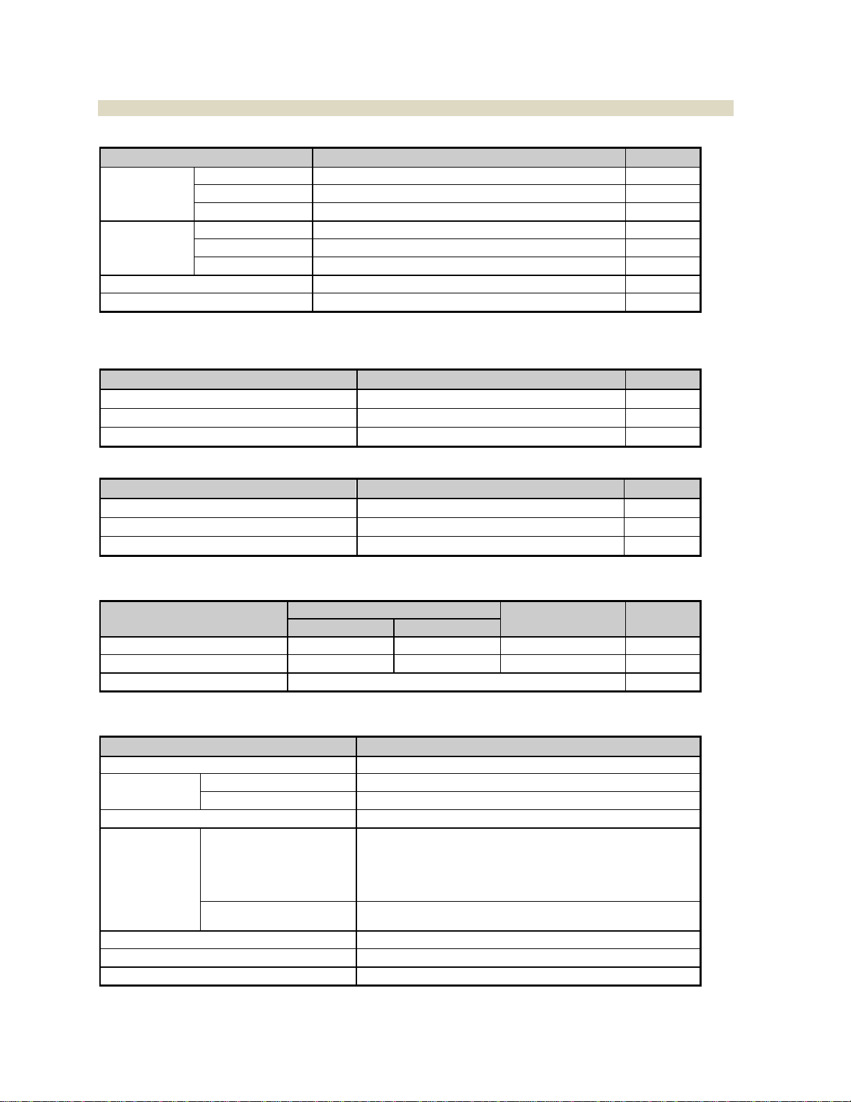
1.3 Pump Specifications
Table 1: Dimensional Specifications
Specification
Value
Unit
Ports
Type
Threaded (NPT) or Flanged (ANSI 150# RF)
–
Suction Size
1.00
in
Discharge Size
0.75
in
Impeller
Diameter
3.75
in
Standard Trims
3.50, 3.25, 3.00, 2.75
in
Type
Open
–
Mounting Bracket
Close-Coupled, Motor Supported 1
–
Motor Frames (C-Face)
NEMA 56C thru 145TC 1
–
1Foot-Mount Motor is required. Power Frame option is available for long-coupling pump mounting bracket to other
motor frames.
Table 2: Performance Specifications
Specification
Value
Unit
Maximum Speed
3600
RPM
Maximum Flow Rate
45
GPM
Maximum Differential Head
65
ft
Table 3: Absolute Temperature & Pressure Ratings
Specification
Value
Unit
Minimum Operating Temperature
-40
°F
Maximum Operating Temperature
500
°F
Maximum Operating Pressure
300 2
PSIG
2For flanged pumps, max rating is 275 PSIG @ -20 to 100°F; for 100 to 500°F, derate by 0.263 PSI/°F.
Table 4: Weight Data
Item
Single Mech. Seal
Packing & Double
Mech. Seal
Unit
Closed Bracket
Open Bracket
Pump with Threaded Ports 3
12
16
26
lb
Pump with Flanged Ports 3
16
20
30
lb
Power Frame
16
lb
3 Weight includes mounting bracket and excludes motor.
Table 5: Material Data
Components
Materials
Pump Body & Impeller
316 Stainless Steel or Alloy-C
Shaft
Pump w/ Closed Bracket
316 SS (Not available in Alloy-C)
Pump w/ Open Bracket
316 SS or Alloy-C 4 / 303 SS 5
O-rings/Gaskets
Teflon, Viton or Graphoil
Dynamic Seal
Single or Double
Mechanical Seal (Type)
Seal Face: Single: Carbon or Teflon ; Double: Carbon
Seal Seat: Silicon Carbide
Seal Wedge: Teflon or Graphoil
Seal Body: Single, 21: 18-8 SS; Single, 9T: 316 SS;
Single, 9A: 316 SS or Alloy-C 4; Double, 9T: 316 SS
Packing
Packing Ring: Braided Teflon or Graphoil
Lantern Ring: Teflon
Mounting Bracket
316 SS (Closed-design) or Cast Iron/Epoxy (Open-design)
Mounting Hardware
18-8 Stainless Steel
Power Frame
Frame: Cast Iron/Epoxy; Shaft: Carbon Steel
4 Material will match Pump Body Material.
5 Part of pump shaft that attaches to motor shaft and does not contact pumped fluid.
Liquiflo Installation, Operation & Maintenance Manual Centry®Series Centrifugal Pumps
Model 620 –Sealed
5
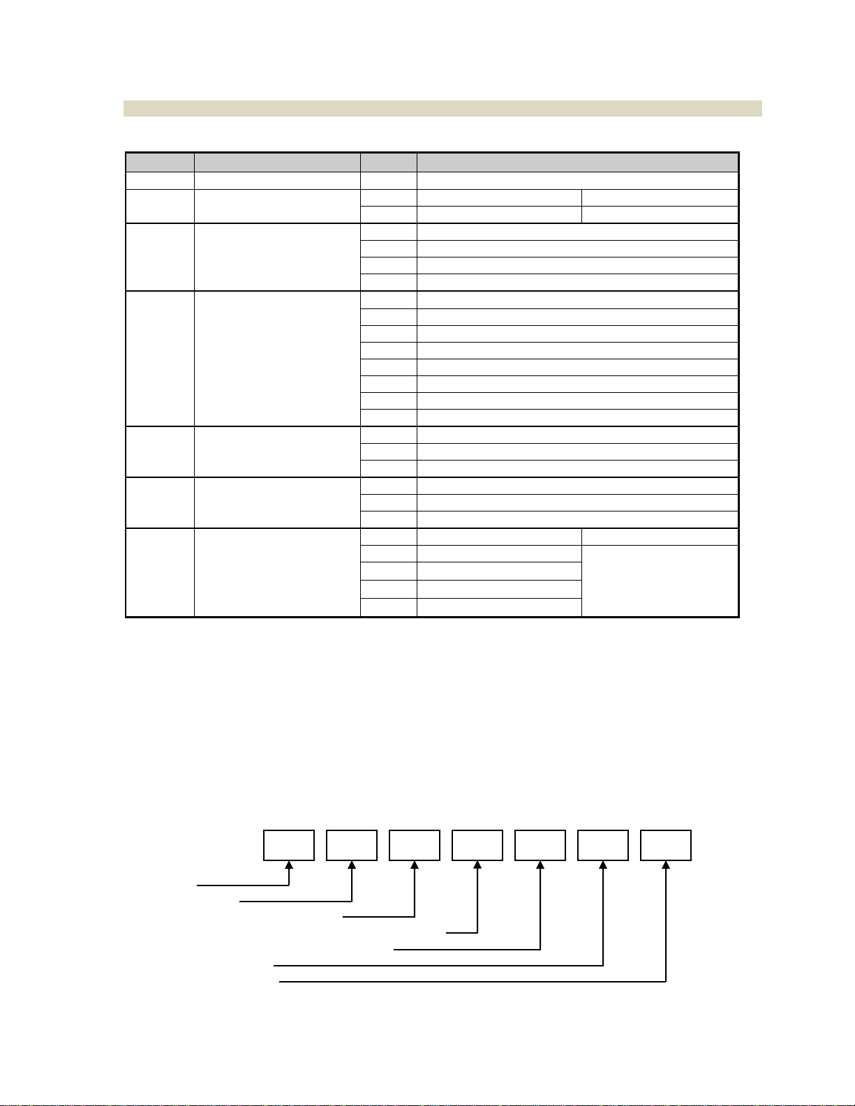
1.4 Model Coding
Table 6: Model Coding for Centry®Model 620 - Sealed
Position
Description
Code
Selection
1
Pump Model
620
Model 620
2
Impeller Size
F
Full-Size –3.75” Diameter
Pos. 7 = 0
R
Reduced-Size
Pos. 7 = 1, 2, 3 or 4
3
Basic Material of
Construction &
Port Type
S
316 SS Construction & NPT Ports
H
Alloy-C Construction & NPT Ports
L
316 SS Construction & Flanged Ports
C
Alloy-C Construction & Flanged Ports
4
Seal Configuration
0
Single Internal Mechanical –Carbon/SiC (Type 21) 1
1
Single Internal Mechanical –Carbon/SiC (Type 9T) 1
2
Single Internal Mechanical –Carbon/SiC (Type 9A) 2
3
Single Internal Mechanical –Teflon/SiC (Type 9A) 2
4
Double Mechanical –Carbon/SiC (Type 9T) 3
5
Lantern Ring –Teflon Packing 4
6
Single Internal Mechanical –Teflon/SiC (Type 9T) 1
7
Lantern Ring –Graphoil Packing 4
5
Motor Frame
(or Power Frame)
0
Close-Coupled –NEMA 56C 5
1
Close-Coupled –NEMA 143TC/145TC 5
P
Pedestal Mount –Power Frame 6
6
O-Rings/Gaskets
0
Teflon Housing Gasket 7
V
Viton O-Rings
G
Graphoil Housing Gasket 7
7
Impeller Trim
(Standard)
0
No Trim
Pos. 2 = F
1
3.50” Diameter
Pos. 2 = R
2
3.25” Diameter
3
3.00” Diameter
4
2.75” Diameter
1 Standard Single Mechanical Seal configuration for 316 SS pumps only. New design utilizes closed 316 SS
Mounting Bracket with integral Seal Housing.
2 Single Mechanical Seal configuration for Alloy-C pumps only. Legacy design utilizes open Cast Iron/Epoxy-
Painted Mounting Bracket with separate Seal Housing.
3 Double Mechanical Seal configuration for Legacy pumps only.
4 Lantern Ring/Packing configuration for Legacy pumps only.
5 Foot-Mount Motor is required. (See cover photos.)
6 Power Frame requires Long-Coupled configuration. (See diagram on page 10.)
7 Seal Seats for Type 21 or 9T Mechanical Seals use Viton O-rings; Seal Seat for Type 9A Single Mechanical Seal
uses Teflon O-ring; Seal Housing for Type 9A Single Mechanical Seal uses Viton O-ring.
Model Coding Example:
Position:
620FS0000=
Model 620
Full-Size Impeller
316 SS Construction & NPT Ports
Single Internal Mech. Seal –Carbon/SiC (Type 21)
Close-Coupled –NEMA 56C Motor Frame
Teflon Housing Gasket
Impeller Trim –No Trim
1
2
3
4
5
6
7
0
0
0
0
S
F
620

Liquiflo Installation, Operation & Maintenance Manual Centry®Series Centrifugal Pumps
Model 620 –Sealed
6
1.5 General Operation
The successful and safe operation of a pump is not only dependent on the pump but also on each of the system
components. It is therefore important to monitor the entire pumping system during operation and to perform the
necessary maintenance to keep the system running smoothly.
A normally operating centrifugal pump will deliver a steady and pulse-less flow, be relatively quiet and have a
predictable flow rate and power requirement based on the impeller size, operating speed, differential head and
fluid specific gravity. Performance curves for centrifugal pumps are normally based on pumping water at room
temperature. Centry Model 620 performance curves can be obtained from the Liquiflo website:
www.liquiflo.com. For viscous liquid applications, a performance correction is required (see Section 3.9).
Pumps operating with mechanical seals should have no leakage of the process fluid. Pumps operating with
packing should have a normal leak rate of 8 to 10 drops per minute with low viscosity liquids. Pumps operating
with a double mechanical seal must be supported with a pressurized fluid lubrication loop. For more information,
see Section 4.2.
If a significant problem is observed during operation, the pump should be stopped so that corrective action can
be taken. The observed problem could have several possible causes, and multiple remedies for each cause.
For help with problem solving, refer to the Troubleshooting Guide given in Appendix 5.
1.6 Maintenance & Repair
Pumps with packing require periodic lubrication or tightening of the gland screws over time. Pumps with a
double mechanical seal require maintenance of the fluid in the lubrication loop. Repair is necessary when the
gland screws cannot stop the packing from leaking excessively, or when the mechanical seal starts to leak, or
when a decrease in head is observed. O-rings and gaskets should always be replaced when rebuilding the
pump.
The main factors affecting the physical wear of the pump are operating speed, differential head, fluid viscosity,
duty cycle, starting and stopping frequency, abrasives in the fluid and the wear properties of the materials.
These factors can cause pump lifetimes to vary significantly from one application to another, making it difficult to
predict when the pump will require maintenance. Therefore, the maintenance schedule for the pump is typically
based on the maintenance history of the specific application. The main indicators that a pump may require
maintenance are the following: (1) decreased flow rate or head, (2) fluid leakage, (3) unusual noise or vibrations
and (4) increased power consumption.
The common repair items of the pump due to erosion wear are the seal components (i.e., packing rings, gland
plate or mechanical seal) and the shaft. Possibly, other pump parts, such as the impeller, volute and seal
housing, may require replacement due to abrasion wear, corrosion wear or cavitation wear.
Before performing maintenance on the pump, review the safety precautions and follow the included instructions.
1.7 Replacement Parts
Replacement parts for the pumps can be purchased from your local Liquiflo distributor. Refer to Appendices 3
& 4 for individual parts information.

Liquiflo Installation, Operation & Maintenance Manual Centry®Series Centrifugal Pumps
Model 620 –Sealed
7
1.8Returned Merchandise Authorization (RMA)
If it is necessary to return the pump to the factory for service,
1) Contact your local Liquiflo distributor to discuss the return, obtain a Returned Merchandise
Authorization Number (RMA #) and provide the distributor with the required information
(see RMA Record below).
2) Clean and neutralize pump. Liquiflo is not equipped to handle dangerous fluids.
3) Package the pump carefully and include the RMA # in a visible location on the outside surface of the
box.
4) Ship pump to factory, freight prepaid.
Returned Merchandise Authorization (RMA) Record
1
RMA #
(Supplied by Distributor)
2
Distributor Name
3
Order Date
4
Customer PO #
5
Return Date
6
Item(s) Returned
7
Serial Number(s)
8
Reason for Return
9
Fluid(s) Pumped
10
Notes
NOTE: Pump must be cleaned and neutralized prior to shipment to the factory.

Liquiflo Installation, Operation & Maintenance Manual Centry®Series Centrifugal Pumps
Model 620 –Sealed
8
Section 2: Safety Precautions
2.1 General Precautions
Always lock out the power to the pump driver when performing maintenance on the pump
Always lock out the suction and discharge valves when performing maintenance on the pump
Never operate the pump without safety devices installed
Never operate the pump with suction and/or discharge valves closed
Never operate the pump out of its design specifications
Never start the pump without making sure that the pump is primed
Never use heat to disassemble the pump
Inspect the entire system before start-up
Monitor the system during operation and perform maintenance periodically or as required by the
application
Decontaminate pump using procedures in accordance with federal, state, local and company
environmental regulations
Before performing maintenance on the pump, check with appropriate personnel to determine if
skin, eye or lung protection is required and how best to flush the pump
Pay special attention to all cautionary statements given in this manual.
Caution!
Failure to observe safety precautions can result in personal injury,
equipment damage or malfunction.

Liquiflo Installation, Operation & Maintenance Manual Centry®Series Centrifugal Pumps
Model 620 –Sealed
9
Section 3: Pump & Motor Installation
3.1 Installation of Pump, Motor & Base
Refer to the Hydraulic Institute Standards for proper installation procedures of the base, pump and motor.
1) The pump inlet should be as close to the liquid source as practical and preferably below it.
Centrifugal pumps cannot be used in a suction lift arrangement unless the pump is primed before
starting. Many issues can be avoided with a flooded suction arrangement.
2) For Close-Coupled Centry pumps, no alignment procedure between the pump and motor is required.
3) For Long-Coupled Pumps utilizing the Power Frame:
(a) The mechanical coupling between the motor and Power Frame has a flexible insert that
must be free to move axially –typically a distance of 1/16 to 1/8 inches –to prevent axial loads
from being transmitted to the power frame.
(b) The motor and Power Frame shafts must be manually aligned to eliminate radial loads on
the pump that will cause vibration and lead to premature pump failure. Alignment of long-
coupled pumps is critical and should be checked by taking measurements of angularity and
parallelism at the coupling. If these are off by more than 0.015 inches (0.4 mm), the assembly
should be realigned. Flexible couplings are not intended to compensate for severe misalignment.
(NOTE: If the pump was delivered as a complete long-coupled assembly, it was properly aligned at
the factory.)
(c) Install the coupling guard over the mechanical coupling and fasten to the base plate.
(NOTE: If the pump was delivered as a complete long-coupled assembly, the coupling guard was
properly installed at the factory.)
NOTE: See pages 48-53 for diagrams of pump mounting options and Section 3.2 for more information about
the power frame.
3.2 Power Frame Option
If the Model Number of the pump contains the letter “P”, the pump was ordered with the Liquiflo Power Frame
option. The power frame is a pedestal that supports the pump and allows it to be long-coupled to a motor. The
power frame has the following uses and advantages:
1) The power frame allows motor frames that are not compatible with the pump mounting bracket to
be coupled to the pump. (For example, motor frames larger than NEMA 145TC, IEC motors or
frames without a C-face can be used.)
2) The power frame enables the motor to be isolated from the pump simply by removing the flexible
coupling. (This is convenient for removing or replacing the motor, or when performing
maintenance.)
3) The power frame thermally isolates the pump from the motor. (The power frame has an integral
cooling jacket that keeps the pedestal’s bearing system cool even when the pump is operating at
maximum temperature.)
The power frame is shown in detail on page 10. The key components of the power frame are described below:
Bearings: The power frame shaft is supported by ball bearings on opposite ends of the pedestal. The oil
reservoir is used to lubricate the bearings. This reservoir is accessible by removing the two 1/8” NPT plugs on
the end of the casing.
Caution!
After performing alignment procedure, ensure that the Coupling Guard is replaced
before operating pump. Do not wear loose clothing around rotating objects.

Liquiflo Installation, Operation & Maintenance Manual Centry®Series Centrifugal Pumps
Model 620 –Sealed
10
Cooling Jacket: The pedestal’s integral cooling jacket is used to keep the bearing system cool when the pump
is operating at elevated temperatures. This is accomplished by circulating a heat transfer fluid thru the jacket.
The cooling loop must be connected to the 1/8” NPT ports on the top and bottom of the casing. (Note: The ports
come with red plastic plugs installed. These plugs should not be removed unless a cooling loop is used.)
Shaft: The motor end (or driven end) of the shaft has a 3/4” diameter. The pump end (or driver end) has a 5/8”
diameter. (Note: Additional dimensional data for the power frame are given on pages 49 and 52-53.)
Power Frame Cross-Sectional View:
A typical long-coupled mounting of the pump and motor, using the power frame option, is shown below:
Power Frame Maintenance:
The power frame is delivered from the factory with its oil reservoir empty. Before operating the power frame, fill the
reservoir with 4 fluid ounces of #20 wt., non-detergent type oil.
The oil in the reservoir should be replaced periodically, with use. To replace the oil: (1) Remove the fill and drain
plugs and collect the used oil in a container, (2) Replace the drain plug, (3) Fill the reservoir with 4 fluid ounces of
clean oil, and (4) Replace the fill plug. (For more information, see the Liquiflo website for the power frame service
manual.)
Caution!
Do not operate the Power Frame without oil in the reservoir. Before performing maintenance, ensure
that the power to the motor is turned OFF and locked out. Do not overfill the reservoir.
Long-Coupled Mounting with NEMA 56 thru 145T or NEMA 56C thru 145TC Motor Frames
OIL FILL PLUG
PLUG
OIL DRAIN PLUG
PLUG

Liquiflo Installation, Operation & Maintenance Manual Centry®Series Centrifugal Pumps
Model 620 –Sealed
11
3.3 General Piping Requirements
Refer to the Hydraulic Institute Standards for piping guidelines.
1) All piping must be supported independently and must line up naturally with pump ports.
2) Piping that handles both hot and cold liquids require proper installation of expansion loops and joints so
that thermal expansion of the piping will not cause misalignment.
3) The piping should be arranged to allow the pump to be flushed and drained prior to the removal of the
pump for servicing. Valves and unions should be installed to allow the pump to be isolated during
maintenance. Valves which open to the full pipe diameter, such as ball valves, should be used.
4) Suction and discharge piping should be the same size or larger than the inlet and outlet ports.
This is especially important for viscous services when the pipe diameter has a large effect on friction
losses and NPSH available.
5) Suction piping should be designed to minimize friction losses. The length of the suction line
should be as short as possible with no sharp turns or bends. Any elbows used should be long radius.
There should be a minimum of five pipe diameters of straight pipe between the elbow and the suction
inlet. Reducers, if used, should be eccentric at the pump suction port.
6) The suction pipe must be submerged sufficiently below the liquid surface to prevent vortices and air
entrapment at the supply.
7) Suction Head (Flooded Suction) Arrangement: Piping should be level or slope gradually downward
from the supply source to eliminate air pockets.
8) Suction Lift Arrangement: The suction pipe must slope continuously upward towards pump suction to
eliminate air pockets. All connections must be air tight. A means of priming the pump must be
provided.
9) Gasket materials used with flanged connections must be compatible with the fluid and operating
temperature.
10) The piping system should be cleaned prior to installation of the pump.
3.4 Strainers & Solids Handling
1) Centry sealed pumps rely on the motor bearings and therefore can tolerate larger particle sizes (up to
0.016 inches or 400 microns) compared with mag-drive pumps that use internal sleeve bearings. If
small abrasive particles are present, they can accelerate wear of internal components and surfaces
over an extended period of time. Although some solids can be tolerated, pumping abrasive particles
is not suggested with these pumps.
2) Regardless of particle size, these pumps are intended for relatively clean liquids where the
general concentration of solids is limited to 2% by volume. Higher concentration may cause the wear
rate to increase, resulting in a decrease in pump performance. In addition to solids concentration, the
specific wear rate also depends on the size, shape and hardness of the particles, the operating speed
and the materials used to construct the pump. Since wear rate is proportional to the square of the
speed, slower operating speeds will substantially increase pump life.
3) While occasional small particles may not be catastrophic to the pump, the use of a strainer on the
inlet will prevent large particulates from entering the pump. If the strainer clogs with material and
is not properly maintained, the pump may be starved of liquid, causing a loss of flow and damaging the
pump via dry-running. When a suction strainer is used, it should have a net open area of at least three
times the suction pipe area.

Liquiflo Installation, Operation & Maintenance Manual Centry®Series Centrifugal Pumps
Model 620 –Sealed
12
3.5 NPSH Requirement
All pumps require sufficient NPSH (Net Positive Suction Head) to function properly. The NPSH available in the
system is the difference between the available suction pressure at the pump inlet and the vapor pressure of the
fluid (which depends on the fluid temperature). The NPSH required by the pump is a function of pump speed
and impeller diameter, and is included with the Performance Curves of the pump. NPSH values are typically
given in units of ft H2O (a) (feet of water, absolute) or m H2O (a) (meters of water, absolute).
The NPSH available in the system must be greater than the NPSH required by the pump or the pump will
go into cavitation, resulting in decreased flow, increased noise emission and potential damage to internal
components.
3.6 Flow Requirements
The pump must be operated with a minimum flow rate to prevent overheating of the process fluid. A
generally accepted industry practice for minimum flow rate is 15% of the flow rate at the Best Efficiency Point
(BEP). Alternatively, the minimum flow rate can be calculated based on the service conditions, power dissipation
and the allowable temperature rise of the fluid. Consult the Hydraulic Institute Handbook or Liquiflo Engineering.
Operating the pump at over 90% of the flow rate at runout should be avoided to prevent a system
fluctuation from causing the pump to “run off the curve,” which can increase the NPSH required by the pump,
possibly going above the NPSH available in the system and causing cavitation.
3.7 Controlling the Flow
A centrifugal pump is a kinetic type pump, and flow is typically controlled by throttling the discharge valve.
The operating point for a centrifugal pump is the intersection of its Head vs. Flow Performance Curve (for a
specific impeller diameter) and the System Resistance Curve (which is a function of the flow rate). Increasing
the flow area of the valve reduces the system resistance and causes the flow rate to increase (i.e., further
opening of the valve moves the operating point to the right on the performance curve). Conversely, decreasing
the flow area of the valve increases the system resistance and causes the flow rate to decrease (i.e., further
closing of the valve moves the operating point to the left on the performance curve).
3.8 Affinity Laws
The performance of a centrifugal pump at any operating speed and impeller diameter can be closely
approximated from the performance at a standard motor speed and impeller diameter by using the Affinity Laws:
Affinity Laws for Centrifugal Pumps
Where, Q= Flow Rate, H= Head, P= Power, n= Speed and D = Impeller Diameter.
3.9 Viscous Fluids
Centry sub-ANSI pumps are generally applied at viscosities under 200 centipoise (cP). For fluid viscosities over
2 cP, a Viscosity Correction per Standard ANSI/HI 9.6.7 is required to size the pump and motor. For sizing
of viscous fluid applications or for more assistance in general selection, contact the local distributor or Liquiflo
Engineering.

Liquiflo Installation, Operation & Maintenance Manual Centry®Series Centrifugal Pumps
Model 620 –Sealed
13
3.10 Motor Selection
1) For the Close-Coupled configuration, the motor frame size is part of the pump model coding and is
selected at the time the pump is ordered. The motor frame must have a C-face for compatibility with the
pump mounting bracket. Refer to Position 5 of the pump model code (see Table 6 on page 5).
2) For the Long-Coupled configuration, the motor is mechanically-coupled to the Power Frame ancillary
device. In this case, any suitable motor frame can be used.
3) For all configurations of the pump, a Foot-Mount motor is required for mounting to a base (see cover
photos and diagram on page 10).
4) The motor must have an enclosure that is compatible with the application conditions. If an explosion-
proof motor is required, the temperature code of the motor must be acceptable for the process fluid.
5) The motor speed and power rating are usually determined at the time the pump is ordered to meet the
specified conditions of service. For thin liquids, the Head vs. Flow Performance Curves can be used
directly to determine the speed and brake horsepower (BHP) requirements, as well as the required
impeller diameter. For liquids heavier than water, the BHP obtained from the Performance Curves
must be multiplied by the Specific Gravity of the liquid to determine the BHP required. For viscous
fluids, a viscosity correction is required (see Section 3.9). Additional power is required to overcome
the friction losses due to viscosity.
3.11 Motor Shaft Direction
The motor shaft must turn in the direction required by the centrifugal pump. Looking at the pump end, the motor
shaft must rotate counter-clockwise, as shown below.
Counter-clockwise
rotation of motor
shaft & impeller

Liquiflo Installation, Operation & Maintenance Manual Centry®Series Centrifugal Pumps
Model 620 –Sealed
14
Section 4: Start-Up & Operation
4.1 Starting the Pump
Before operating the pump, inspect the hydraulic system and verify the following:
1) Pump Construction: The materials of construction of the pump must be compatible with the process
fluid.
2) Pump Mounting: The pump must be securely fastened to the base and ground using the basic
installation procedures as outlined by the Hydraulic Institute.
3) Alignment: Pumps that are close-coupled to a motor do not require manual alignment. Those that are
long-coupled to a motor, using the power frame option, will require alignment of the motor and power
frame shafts (see Section 3.1).
4) Piping Layout: Process piping procedures are extremely important and must be performed in
accordance with the Hydraulic Institute. As a minimum, inlet piping must be equal to or larger in
diameter than the pump inlet size. Twists and bends of pump inlet piping should be kept to an absolute
minimum. Ensure that adequate NPSH is available for the pump to operate properly.
5) Motor Enclosure: The motor enclosure must be suitable for the conditions of service.
6) Electrical Hook-up: The electrical connections to the motor should be performed by a qualified
electrician. It is critical that the supply voltage match the motor nameplate voltage or serious motor
damage or fire can result.
6) Safety: Never operate a long-coupled pump without the coupling guard installed. A power sensor
should be installed to stop the motor in the event of a loss-of-load or overload condition.
8) Pumps with Packing or Double Mechanical Seal: These seal types have special requirements (refer
to the information in Section 4.2).
9) Valves: Open all suction and discharge valves before operating the pump or damage or malfunction
may result. (Note: Suction valves must be open to supply the pump with fluid and a method of priming
the pump must be available to prevent dry-running. Fully closing a discharge valve when the pump is
operating will cause circulation of fluid inside the pump’s volute. Operating the pump continuously in
this state will cause significant heating of the fluid.)
10) Priming & Direction of Rotation: Prime the pump and then briefly jog the motor to assure proper
motor direction. Motor shaft direction must be counter-clockwise, as seen from the pump end (see
page 13). Remove the vent plug located at the top of the volute to purge any air trapped in the pump
(see diagram on page 16 for location of volute plugs).
Caution!
Always prime pump before operating. Do not run the pump dry for more
than a few seconds or damage to the seal will result. Extended dry running
can damage other internal parts.
Caution!
Do not wear loose clothing around rotating objects.

Liquiflo Installation, Operation & Maintenance Manual Centry®Series Centrifugal Pumps
Model 620 –Sealed
15
4.2 Packing & Double Seal Requirements
4.2.1 Packing Seal
1) Packed pumps require some type of lubrication around the pump shaft or the packing
will overheat and score the shaft. This can be achieved with grease, an external flush or
nothing at all. If grease is used, it should be compatible with the process fluid (i.e., non-soluble
and non-reactive). Inject grease into the top fitting after removing the drain plug on the
opposite side of the seal housing. This greasing should be repeated periodically. (Note:
Replace drain plug after greasing.) If nothing is used, there must be some leakage out of the
pump so the packing is well lubricated by the pumpage. (This is typically accomplished with
liquids of relatively low viscosity.)
2) The packing compression must be adjusted during pump operation. Do not over-tighten the
packing gland screws. This will burn the packing and damage the shaft. Packed boxes
should leak at the rate of approximately 8 to 10 drops per minute. Tighten the gland screws
1/4 turn at a time and allow the leakage rate to stabilize. Repeat until a rate of about 8 to 10
drops per minute is stable.
4.2.2 Double Mechanical Seal
For pumps equipped with a double mechanical seal, a fluid lubrication loop, to pressurize the
seal chamber, is required. The seal chamber should be kept at approximately 5 to 20 PSI
higher than the discharge pressure. In addition, the flow rate through the seal chamber should
be approximately 1/8 GPM. This is required to cool and flush the seal faces. For fluids with
specific heat values other than 1.0 (i.e., water) the flow rate should be adjusted.
4.3 Operation & Troubleshooting
Before starting the pump, review the steps in Section 4.1. If the pump has packing or a double mechanical seal,
the seal must be supported as explained in Section 4.2 above.
A normally operating centrifugal pump will deliver a steady and pulse-less flow, be relatively quiet and have a
predictable flow rate based on the impeller size, operating speed and differential head across the pump. Refer to
the performance curves for Centry Model 620, which are available on the Liquiflo website. (Note: If the fluid
viscosity is significantly higher than the viscosity of water, a performance correction is required as explained in
Section 3.9.)
The differential pressure can be measured with calibrated pressure gauges close to the suction and discharge
ports. (Note: The true differential pressure must take into account the difference in gauge elevations and the
velocity head (dynamic pressure) differential resulting from the increase in fluid velocity thru the centrifugal pump.
Pressure is related to Head by the following formula: Pressure [PSI] = (Head [feet] x SG)/2.31, where SG is the
Specific Gravity of the fluid.) The flow rate can be measured with a calibrated flowmeter in the discharge line.
After priming and start-up, monitor the pump for several minutes to ensure proper operation. If excessive noise
is heard, or product leakage is observed, or performance is not as expected, stop the pump and refer to
Appendix 5 for troubleshooting.
Caution!
Failure to properly support the Double Mechanical Seal when operating
the pump will cause premature seal wear and leakage.
Caution!
Do not over-tighten the packing gland screws.
Damage to the packing and shaft will result.
Liquiflo Installation, Operation & Maintenance Manual Centry®Series Centrifugal Pumps
Model 620 –Sealed
16
Section 5: Maintenance & Repair
The major maintenance items for the sealed pump are tightening of the gland screws for packed pumps and
periodic lubrication of the packing (if grease is being used), and maintenance of the barrier fluid in the double
mechanical seal loop. When the gland screws cannot stop the packing from leaking excessively, or the
mechanical seal starts to leak, or a decrease in head is observed, repair is necessary. O-rings and gaskets
should always be replaced when rebuilding the pump.
5.1 Work Safety
Before performing maintenance, review the safety precautions given in Section 2 (see page 8).
5.2 Removal from System
Before servicing, prepare the pump as follows:
1Flush the pump.
2Stop the motor and lock out the electrical panel.
3Close the suction and discharge isolation valves.
4Disconnect the pump from the system piping.
NOTE: The pump has a back pullout design. This feature makes it unnecessary to disconnect the volute from the
system piping. The pump can be drained of residual liquid by removing the 1/8” NPT plugs from the volute (see
diagram below) and the seal housing, when applicable (see drawings in Appendix 4).
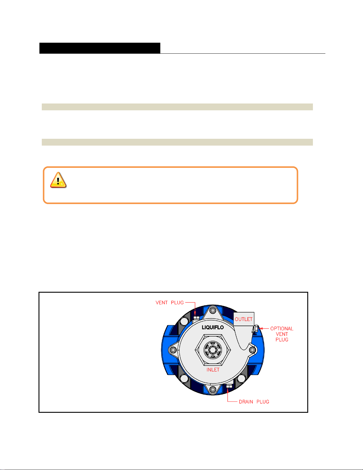
Location of Vent & Drain Plugs:
The pump has two 1/8” NPT plugs
located on the top and bottom of the
volute. Another 1/8” NPT port and
plug may be present on the pump’s
outlet port (see diagram at right).
Caution!
If the pump was used with hazardous or toxic fluids, it must be flushed and decontaminated
prior to removal from the system piping. Refer to the Material Safety Data Sheet (MSDS)
for the liquid and follow all prescribed safety precautions and disposal procedures.

Liquiflo Installation, Operation & Maintenance Manual Centry®Series Centrifugal Pumps
Model 620 –Sealed
17
5.3 PUMP DISASSEMBLY
Follow the procedure below and refer to the Sectional and Exploded View drawings in Appendix 4. Drawing
reference numbers are given in parentheses in the following procedure.
1A. Pump with Closed-Bracket Design: Remove the four sets of volute mounting bolts (6); then
separate the volute (2) from the assembly.
B. Pump with Open-Bracket Design: Remove the four sets of volute mounting bolts (6), nuts (7)
and lock washers (8); then separate the volute (2) from the assembly.
NOTE: The pump has a back pullout design. This feature makes it unnecessary to disconnect the volute
from the system piping.
2 Remove the housing O-ring or gasket (5) and discard.
3 Removal of Impeller:
A. Pump with Type 21 or 9T Single Mechanical Seal, Double Mechanical Seal or Packing:
Loosen the impeller setscrew (9) and then remove the impeller (1) from the pump shaft (4).
B. Pump with Type 9A Single Internal Mechanical Seal: Remove the impeller screw (9) and then
remove the impeller (1) and lock collar (10) from the pump shaft (4).
NOTE: Removal of the impeller screw is facilitated by using a second wrench on the flats of the pump shaft.
4 Pump with Open-Bracket Design Only: Loosen the two setscrews (11) that secure the pump shaft
(4) to the driver shaft.
NOTE: The driver shaft can be the motor shaft or the power frame shaft.
5A. Pump with Closed-Bracket Design: Remove the bracket mounting bolts (15) and lock washers
(16) and then separate the bracket (14), which contains the seal components, from the motor.
Then loosen the two setscrews (11) and remove the pump shaft (4) from the motor shaft.
B. Pump with Open-Bracket Design: Remove the seal housing (3), which contains the seal and
shaft, as a complete assembly.
Caution!
Be certain that the power to the motor is turned OFF and locked out.
Pump with Open-Bracket Design
Pump with Closed-Bracket Design

Liquiflo Installation, Operation & Maintenance Manual Centry®Series Centrifugal Pumps
Model 620 –Sealed
18
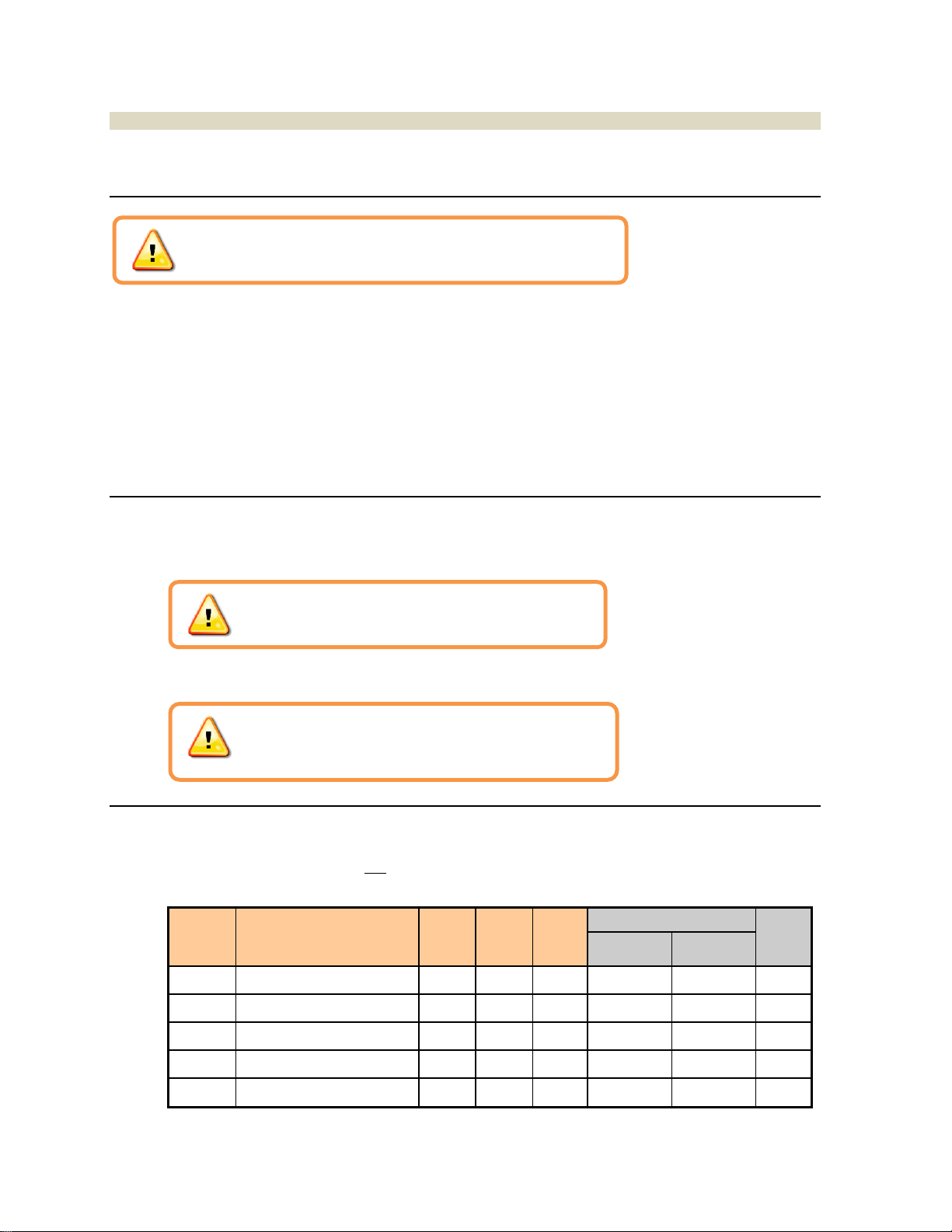
Removal of Seals:
6The pump can have any one of five different types of seals installed. Refer to the applicable section
below for removal of the pump’s seal:
Section
Seal Removal
Mech.
Seal
Type
Pos.
4
Code
Page
#
Reference Drawings
Page
#s
Sectional
Exploded
View
A
Single Internal Mech. Seal
21
0
18
#1
#1 / #1A
38-39
B
Single Internal Mech. Seal
9T
1, 6
18
#2 / #2A
#2
40-41
C
Single Internal Mech. Seal
9A
2, 3
18
#3
#3
42-43
D
Double Mechanical Seal
9T
4
19
#4
#4
44-45
E
Packing Seal
---
5, 7
19
#5
#5
46-47
A. Single Internal Mech. Seal, Type 21 Removal (Refer to Drawings on Pages 38-39)
A1 Remove the unattached Type 21 single mechanical seal components (17 & 20) from the
seal housing section of the mounting bracket (14). These components are the sealing
ring, holder assembly (consisting of the drive band, retainer and flexible bellows), spring
and spring support washer.
A2 Press out the seal seat (18) from the Seal Housing. Discard the seal seat O-ring (19).
B. Single Internal Mech. Seal, Type 9T Removal (Refer to Drawings on Pages 40-41)
B1 Remove the unattached Type 9T single mechanical seal (17) from the seal housing
section of the mounting bracket (14).
B2 Press out the seal seat (18) from the Seal Housing. Discard the seal seat O-ring (19).
C. Single Internal Mech. Seal, Type 9A Removal (Refer to Drawings on Pages 42-43)
C1 Remove the seal seat (18) and seal seat
O-ring (19) from the shaft (4). Dispose of
the seal seat O-ring.
C2 Remove the shaft (4) and wiper (12) from
the seal housing (3)
C3 Remove the Type 9A mechanical seal (17)
by pressing it out of the seal housing (3).
Liquiflo Installation, Operation & Maintenance Manual Centry®Series Centrifugal Pumps
Model 620 –Sealed
19
D. Double Mechanical Seal, Type 9T Removal (Refer to Drawings on Pages 44-45)
D1 Remove the two gland screws (20).
D2 Withdraw the shaft assembly, which consists of the shaft (4), mechanical seal (17),
outer seal seat (22) and gland plate (12), from the seal housing (3).
D3 Loosen all setscrews on the metallic body of the mechanical seal (17); then slide the
seal off the shaft (4).
D4 Remove the outer seal seat (22) from the shaft (4) and dispose of the O-ring (23).
D5 Remove the gland plate (12) from the shaft (4).
D6 Remove the inner seal seat (18) by pressing it out of the seal housing (3).
D7 Remove the O-ring (19) from the inner seal seat (18) and dispose of the O-ring.
E. Packing Seal Removal (Refer to Drawings on Pages 46-47)
E1 Remove the split gland (12) by removing the two gland screws (20).
E2 Remove the shaft (4) from the seal housing (3).
E3 Remove old packing rings (17) and lantern ring (18) from the seal housing (3).
NOTE: The use of a packing puller or hooked tool will facilitate removal of the packing and
lantern ring.
END OF DISASSEMBLY PROCEDURE
Caution!
Do not remove the Mechanical Seal from the shaft unless a new
replacement seal is available; the Seal Wedges will be damaged
upon removal.
Liquiflo Installation, Operation & Maintenance Manual Centry®Series Centrifugal Pumps
Model 620 –Sealed
20
5.4 PUMP ASSEMBLY
Follow the procedure below and refer to the Sectional and Exploded View drawings in Appendix 4. Drawing
reference numbers are given in parentheses in the following procedure.
Bracket Installation –Legacy Design:
NOTE: Step 1 applies only to pumps with Type 9A Single Mechanical Seal,Double Mechanical Seal or
Packing. If the blue-painted pump mounting bracket is already installed, or for Type 21 and Type 9T Single
Mechanical Seals, start with Step 2.
1Install the mounting bracket (14) to the motor or power frame using four sets of bolts (15) and
lockwashers (16).
NOTE: For pumps with a Packing Seal or Double Mechanical Seal, a spacer plate (10) and longer mounting
bolts (15) are required. Refer to Appendix 1 for the lengths and torque specifications of the bolts.
Shaft Inspection & Polishing:
2 Inspect the pump shaft (4) and verify that it has not been scored or worn from prior use.
3Remove any burrs or scratches on shaft (4), by polishing, prior to reassembling pump.
Installation of Seals:
4The pump can have any one of five different types of seals. Refer to the applicable section below for
installation of the pump’s seal:
Section
Seal Installation
Mech.
Seal
Type
Pos.
4
Code
Page
#s
Reference Drawings
Page
#s
Sectional
Exploded
View
A
Single Internal Mech. Seal
21
0
21-22
#1
#1 / #1A
38-39
B
Single Internal Mech. Seal
9T
1, 6
23-26
#2 / #2A
#2
40-41
C
Single Internal Mech. Seal
9A
2, 3
27-28
#3
#3
42-43
D
Double Mechanical Seal
9T
4
29
#4
#4
44-45
E
Packing Seal
---
5, 7
30
#5
#5
46-47
Caution!
This step is important to ensure the proper fit of parts and
to prevent scoring of the seal on reassembly.
Caution!
If the shaft exhibits excessive wear, it must be replaced.
Caution!
Be certain that the power to the motor is turned OFF and locked out.
Table of contents
Other Liquiflo Water Pump manuals

Liquiflo
Liquiflo H-Series Instruction manual

Liquiflo
Liquiflo MAX Series User manual

Liquiflo
Liquiflo ROTOGEAR H Series Manual

Liquiflo
Liquiflo FTS Series Setup guide

Liquiflo
Liquiflo FTS300 Series Setup guide

Liquiflo
Liquiflo FTS400 Series Setup guide

Liquiflo
Liquiflo POLY-GUARD Series Instruction manual

Liquiflo
Liquiflo H-Series Owner's manual
Popular Water Pump manuals by other brands

Becker
Becker VT 4.16 operating instructions

North Star
North Star MA1578111Y owner's manual

NIKKISO
NIKKISO CHEMIPON BX Series instruction manual

Zoeller
Zoeller Home Guard Max 503 instructions

Advantage Controls
Advantage Controls MicroTron C Series Installation maintenance repair manual

DAB PUMPS
DAB PUMPS DTRON3 Series Instruction for installation and maintenance


