Liquiflo ROTOGEAR H Series Manual

INSTALLATION and MAINTENANCE MANUAL
3and H-SERIES
ROTOGEARASEALED PUMPS
TABLE OF CONTENTS
General Instructions
Symbol Explanation
Pump and Motor Installation
Start Up
Special Precautions for various seals
Removal from System
Maintenance and Repair
Pump Disassembly
Section (A) Packed stuffing box
Section(B) LipSeal
Section (C) Single internal mechanical seal
Section (D) External mechanical seal
Section (E) Double mechanical seal
Trouble Shooting Document No.: 3.20.073
Liquiflo Equipment Co. 443 North Avenue Garwood, NJ 07027 USA Tel 908-518-0666 Fax 908-518-1847

P. 2
GENERAL INSTRUCTIONS
This Manual covers the “3” and “H” series Sealed pumps.
Upon receipt of your Liquiflo pump verify:
A) The equipment has not been damaged in transit.
B) The pump model number and serial number are stamped on the pump's rear housing.
Model:_______________________ Serial No.____________________
NOTE: By adding a K prior to the pump's model number a repair kit can be obtained
which consists of the following parts: drive and idler gears, drive and idler shafts, retaining
rings, wear plates, keys, housing and bearing lock pins, o-rings and bearings.
SYMBOL EXPLANATION
A) Work Safety Symbol
This symbol indicates remarks applicable to operational safety,
where risks for health and life of personnel may be posed. All
cautions should be passed on to other users.
B) Attention Symbol
Special attention must be paid in order to maintain a correct
operating procedure and to avoid damage to the pump and/or other
plant equipment.
INSTALLATION OF PUMP AND MOTOR ASSEMBLY
All items included in this section.
The following should be observed for proper installation of the pump.
A) Pump should be accessible for servicing and inspection.
B) The foundation area should be rigid and level for maintaining pump alignment.
C) The inlet should be as close to the liquid source as practical and preferably below it.
D) Piping should be supported. Do not use the pump as a pipe hanger.
E) Install valves and unions to isolate the pump during maintenance.
ATTENTION
ATTENTION
!
RECORD

P. 3
F) Suction and discharge piping should be the same size or larger than the inlet and
outlet ports.
G) Clean piping as necessary to remove dirt, grit, weld slag, etc.
H) If the Liquiflo pump was delivered as a complete assembly, it was properly aligned
at the factory. Alignment should be checked by taking measurements at the
coupling. Flexible couplings are not intended to compensate for misalignment.
Therefore, both angularity and parallelism should be checked and corrected. If these
are off, by more than 0.015 inches (0.4 mm), the assembly should be realigned.
I) For further instructions on mounting or installing your pump, refer to the Hydraulics
Institute Handbook.
J) A positive displacement pump should have a pressure relief valve installed in the
discharge line.
K) Maximum particle size capable of being passed by the pump is 37 microns. A filter
of at least 400 U.S. Mesh should be installed in the suction line. 312, H12 and 314
particle size is 60 microns with a filter mesh of 230 U.S. Concentration of solids,
exceeding 1% is not recommended as wear rates will increase to unacceptable
levels.
START UP
Insure motor is locked out, prior to rotating pump by hand.
A) Turn the pump by hand to insure that it turns freely.
B) Jog the motor to check the rotation. As viewed from the pump end a clockwise
rotation of the motor will result in fluid discharge to the left. Counterclockwise
rotation will result in fluid discharge to the right. The 312, 314 and the H series are
opposite.
C) The pump should be operated with at least a 20-psi (1.4 bar) differential pressure.
D) The pump is capable of pulling a dry lift, but it is still recommended to prime the
pump prior to start up.
E) Do not operate the pump without fluid in it for more than 30 seconds.
SPECIAL PRECAUTIONS FOR VARIOUS SEALS
A) If packing was specified for the stuffing box the following should be observed.
!

P. 4
1) A packed pump can be run with grease, an external flush, or nothing at all.
If grease is used, it should be compatible with the fluid being pumped (i.e. non-
soluble and non-reactive). Inject grease into the fitting after removing the drain plug
on the opposite side. This greasing should be repeated periodically. If nothing is
used, there must be some leakage out of the pump so the packing is well lubricated.
NOTE: Replace drain plug after greasing.
2) Don't over tighten the packing screws. You will burn the packing and
damage the shaft. Packed boxes should leak at a rate of 8 to 10 drops per minute.
Tighten the gland screws 1/4 turn at a time to allow the leakage rate to stabilize.
Repeat until a rate of 8-10 drops per minute is stable.
Do not wear loose clothing around rotating objects.
B) If the pump is equipped with a double mechanical seal, a lubrication loop to
pressurize the seal chamber is required. The seal chamber should be kept at
approximately 5 to 20 psi (.3 to 1.4 bar) higher than the discharge pressure. In
addition, the flow rate through the seal chamber should be approximately 1/8 GPM,
for fluids with specific heat values other then 1.0 (i.e. water) the flow rate should be
adjusted.
Insure coupling guard is replaced prior to starting.
REMOVAL FROM SYSTEM
When the pump is handling flammable, toxic or hazardous fluid, flush the
pump prior to removal from the piping system. Prior to flushing and disassembly
consult the Material Safety Data Sheet (MSDS) for the pumped fluid to ensure
procedures and precautions as specified are adhered to. Exercise extreme care to
avoid contact with the fluid.
Insure that the motor is locked out.
MAINTENANCE AND REPAIR
The pump has internal bearings and wear plates, which require replacement over
time.
Insure the pump's motor switch is in the "off" position and locked
out.
ATTENTION
ATTENTION
ATTENTION
!
ATTENTION

P. 5
The balance of the manual describes the maintenance procedures for the specific
type of seal involved.
Maintenance for a sealed gear pump is minimal. Periodic lubrication of the packing
and tightening of the gland screws and fluid in the double seal loop are the major
maintenance items. When the gland screws cannot stop the packing from leaking
excessively, or the mechanical seal starts to leak, or a decrease in head is observed, repair is
necessary.
PUMP DISASSEMBLY
1) Remove the coupling guard and disconnect the flexible coupling.
2) Disconnect the pump's center housing (21) from the piping and remove the pump.
3) Remove the gland screws (16), lock washers (19) and the gland (17).
Note: For the 312, H12 and 314 go to step 12.
4) (A) Refer to section (A) for removal of the packing.
(B) Refer to section (B) for removal of the lip seal.
(C) Refer to section (C) for removal of a single seal.
(D) Refer to section (D) for removal of an external seal.
(E) Refer to section (E) for removal of a double seal.
5) Remove the four housing bolts (4), housing nuts (10) and lock washers (15) which
secure the front housing (8) and rear housing (2) to the center housing (21).
6) Remove the wear plates (7) and housing o-ring (5).
7) Remove the drive and idler shaft assemblies.
8) Remove the gears (22) and (6) from the shaft by removing the retaining rings (14).
Remove retaining rings by inserting a pointed tool in the split and prying off.
NOTE: Exercise care during removal as not to damage the grooves.
Front Housing
Gear

P. 6
9) Remove the keys (23A) and (23B).
10) Remove the bearings (3) and the bearing lock pins (13) from the front and rear
housings. Removal is generally accomplished by destroying the bearing.
NOTE: When removing the bearings be careful not to damage the bearing
bores.
11) Remove any burrs on shafts and bearing bores by
polishing prior to reassembling pump.
NOTE: This is important to insure the proper fit of
parts and the prevention of leaks.
Caution: Do not reuse 0-rings, bearings and
retaining rings.When tightening the center housing bolts use a
star pattern torque sequence on the fasteners to insure even compression on the O-ring’s
surface. Repeat this process several times waiting between re-tightening. This is necessary
as the Teflon®will cold flow.
Bolt Size Torque in-lbs (NM)
10-32 UNF 28 (3.2)
1/4-20 UNC 60 (6.7)
5/16-18 UNC 90 (10)
312, H12 and 314 Continued from Step 2
Caution: The 312, H12 and 314 pumps weigh approximately 55 and 70 lbs (25 and 32
kg), respectively.
12) Remove the six housing screws (4) and lockwashers (15) that secure the front
housing (8) to the center housing (21).
13) Go to step listed above 6 through 9 listed above.
Front Housing
Rear Housing

P. 7
14) Remove the six housing screws (4) and lockwashers (15) securing the rear housing
(2) to the center housing (21).
15) Go to steps 10 and 11 listed above.
Section (A) Packed Stuffing Box
If the packing leaks excessively, it will have to be replaced.
1) The use of a packing puller will help facilitate the removal of the packing. Remove
old packing (18) and lantern ring (11).
2) Insert three rings of packing into the stuffing box
staggering the split by at least 90 to 120 degrees.
3) Insert lantern ring.
4) Insert two more rings (three more for the 312, 314 and
H12) of packing staggering as described above.
5) Install split gland and gland screws.
Do not over tighten the gland screws as the packing should leak at a
rate of 8 to 10 drops per minute.
Section (B) Lip Seal
If the lip seal leaks excessively it needs to be replaced.
1) Remove the lip seal (11) from the front housing.
2) Install a new lip seal.
NOTE: If the drive shaft exhibits excessive wear the shaft must be replaced.
3) Install gland, gland screws and lock washers. Tighten gland screws to 90 in-lbs
(10NM).
Applicable to all Mechanical Seals
A) If the mechanical seal leaks excessively it needs to be replaced.
B) Do not scratch or handle the lapped face of the seal.
ATTENTION
ATTENTION

P. 8
C) Remove all burrs and setscrew marks from drive shaft.
D) Do not remove the seal unless a new replacement seal is available; because the seal's
wedge will be damaged upon removal.
E) Do not reuse 0-rings.
Section (C) Single Internal Mechanical Seal
1) Remove the mechanical seal (11) from the front housing first by removing the 1/8
inch NPT plug (9) and then loosening the four setscrews which are accessible
through the 1/8 inch NPT opening by rotating the pump shaft.
2) Remove the seal seat (24) and the seal seat gaskets or O-rings (18) from the gland.
3) Put new seal seat gaskets or O-ring on the seal seat and install into gland.
4) Install the mechanical seal (face side out), with retaining clips still on; onto the drive
shaft being careful not to damage the seal's wedge. Then remove the retaining clips.
Slide the seal into the seal chamber centering the set screws in the 1/8 inch NPT
opening.
5) Using gland plate (with seat installed) press seal into seal chamber until a gap of .09
inches (2.3 mm) exists between the gland plate and the front housing. Then tighten
the setscrews accessible through the 1/8 inch NPT opening. Rotate shaft and tighten
the remaining three set screws.
6) Install gland screws and lock washers and tighten to 90 in-lbs (10 NM).
Seal Removal
S
eal Install
at
i
o
n
O-
r
ing typ
e
seal seat
and gland.
Gasket type
seal seat

P. 9
7) Coat the 1/8 inch NPT plugs (if applicable) with a suitable pipe sealant, install into
the front housing and tighten.
Section (D) External Mechanical Seal
Note: Mechanical seal must be removed first to provide access to the gland plate.
The 312 and 314 have no gland plate.
1) Remove the mechanical seal (11) from the drive shaft by loosening the four set
screws.
Note: For the 312 and 314 refer to Steps 2 through 6 listed below under Double
Mechanical Seal and Step 8 in this Section.
2) Remove the gland screws (16), lock washers (19) and gland (17).
3) Remove the seal seat (25) and the two seal seat gaskets (18).
4) Install new seal seat gaskets on the seal seat.
5) Install gland, gland screws and lock washers.
6) Install the mechanical seal with retaining clips onto the drive shaft being careful not
to damage the seal's wedge. Then remove the retaining clips. Slide the seal up to
the seal seat.
7) Compress the mechanical seal by .09 inches (2.3 mm) and then tighten the four
setscrews.
Section (E) Double Mechanical Seal
1) To remove the mechanical seal (11) from the front housing, first remove the 1/8
inch NPT plug (9) and then loosen the four setscrews which are accessible through
the 1/8 inch NPT opening by rotating the pump shaft.
NOTE: For further seal removal the pump must be disassembled.
2) Refer to paragraph (5) through (7) in the pump disassembly section.
3) Remove the seal seat (inner) (26) and o-ring (25) from the front housing by
pressing it out.
4) Install a new o-ring on the seal seat (inner).
Seal Seat Inner

P. 10
5) Press assembly into the front housing.
6) Install the mechanical seal with retaining clips onto the drive shaft being careful not
to damage the seal's wedge on the keyway. Then remove the retaining clips. Slide
the seal into the seal chamber.
4) Remove the drive side seal seat (24) and the seal seat gaskets (18) or O-rings from
the gland.
5) Install new seal seat gaskets or O-rings on the seal seat and install into gland.
6) Install gland, gland screws and lock washers. Tighten gland screws to 90 in-lbs (10
NM).
7) Using an Allen (Hex) Key slide seal retainer (metal cartridge) to position set screws
centrally within the 1/8 inch NPT openings. Rotate shaft and tighten all four (4) set
screws.

P. 11
Trouble Shooting Guide
Problem Possible Cause Remedy
Pump not primed
Verify suction pipe is
submerged
Increase suction pressure
Open suction valve
Wrong direction of rotation Reverse motor leads
Reverse suction and
discharge piping
Valves closed Verify valves are open
Bypass valve open System pressure higher than
relief setting
Close bypass valve
Air leak in suction
Tighten connections
Apply sealant to all threads
Verify suction pipe is
submerged
Clogged strainer Clean strainer
Pump worn Rebuild pump
No Discharge
Magnetic coupling broken
free Stop pump. Wait till there is
no rotation restart pump
Inlet pressure to low
Increase suction pressure
Verify suction piping is not
to long.
Fully open any suction
valves
Clogged strainer Clean strainer
Speed to low
Increase driver speed if
possible
A larger size pump may be
needed.
Bypass valve open System pressure higher than
relief setting
Close bypass valve
Insufficient Discharge
Pump worn Rebuild pump
Increase in fluid viscosity Heat fluid to reduce
viscosity
Decrease pump speed
Loss of suction after
satisfactory operation Air leaks in suction line
Tighten connections
Apply sealant to all threads
Verify suction pipe is
submerged

P. 12
Problem Possible Cause Remedy
Fluid viscosity higher than
specified
Heat fluid to reduce
viscosity
Decrease pump speed
Increase driver horsepower
Gear clearances insufficient
for viscosity Purchase gears trimmed for
the correct viscosity
Excessive power
consumption
Differential pressure greater
than specified Increase pipe diameter
Abrasives in fluid Install suction strainer
Corrosion wear Materials of construction
not acceptable for fluid
being pumped
Extended dry running Install power sensor to stop
pump
Discharge pressure too high Increase pipe diameter
Decrease pipe run
Rapid pump wear
Misalignment Align pump and motor

1 CPS - Fluid-Water
Chemical Processing Pumps
Model 31F
100 CPS - Oil
DIFFERENTIAL PRESSURE (PSI)
0.6
0.5
0.4
0.3
0.2
0.1
0
80
6040
20 100
0
0.20
0.15
0.10
0.05
0
1750
1500
1140
900
POWER (BHP)
LPM
2.2
2.0
1.8
1.6
1.4
1.2
1.0
0.8
0.6
0.4
0.2
0
FLOW (GPM)
600
1750
024 6 8
BAR
600
DIFFERENTIAL PRESSURE (PSI)
0.6
0.5
0.4
0.3
0.2
0.1
0
80
6040
20 100
0
1750
1500
1140
900
POWER (BHP)
024 6 8
BAR
FLOW (GPM)
600
1750
LPM
2.2
2.0
1.8
1.6
1.4
1.2
1.0
0.8
0.6
0.4
0.2
0
0.20
0.15
0.10
0.05
0
600

1 CPS - Fluid-Water
Chemical Processing Pumps
Model 33F
100 CPS - Oil
024 6 8
BAR
DIFFERENTIAL PRESSURE (PSI)
1.6
1.4
1.2
1.0
0.8
0.6
0.4
0.2
0
80
6040
20 100
0
1750
1500
1140
900
POWER (BHP)
FLOW (GPM)
600
1750
0.4
0.3
0.2
0.1
0
600
LPM
6
5
4
3
2
1
0
024 6 8
BAR
DIFFERENTIAL PRESSURE (PSI)
80
6040
20 100
0
1750
1500
1140
900
POWER (BHP)
FLOW (GPM)
600
1750
600
1.6
1.4
1.2
1.0
0.8
0.6
0.4
0.2
0
LPM
6
5
4
3
2
1
0
0.4
0.3
0.2
0.1
0

1 CPS - Fluid-Water
Chemical Processing Pumps
Model 35F
100 CPS - Oil
024 6 8
BAR
DIFFERENTIAL PRESSURE (PSI)
4.0
3.5
3.0
2.5
2.0
1.5
1.0
0.5
0
80
6040
20 100
0
1750
1500
1140
900
POWER (BHP)
FLOW (GPM)
1750
600
600
LPM
15
12
9
6
3
0
0.8
0.7
0.6
0.5
0.4
0.3
0.2
0.1
0
024 6 8
BAR
DIFFERENTIAL PRESSURE (PSI)
80
6040
20 100
0
1750
1500
1140
900
POWER (BHP)
FLOW (GPM)
600
1750
600
4.0
3.5
3.0
2.5
2.0
1.5
1.0
0.5
0
LPM
15
12
9
6
3
0
0.8
0.7
0.6
0.5
0.4
0.3
0.2
0.1
0

1 CPS - Fluid-Water
Chemical Processing Pumps
Model 35R
100 CPS - Oil
024 6 8
BAR
DIFFERENTIAL PRESSURE (PSI)
3.0
2.5
2.0
1.5
1.0
0.5
0
80
6040
20 100
0
1750
1500
1140
900
POWER (BHP)
FLOW (GPM)
1750
600
600
LPM
11
10
9
8
7
6
5
4
3
2
1
0
0.6
0.5
0.4
0.3
0.2
0.1
0
024 6 8
BAR
DIFFERENTIAL PRESSURE (PSI)
80
6040
20 100
0
1750
1500
1140
900
POWER (BHP)
FLOW (GPM)
600
1750
3.0
2.5
2.0
1.5
1.0
0.5
0
600
LPM
11
10
9
8
7
6
5
4
3
2
1
0
0.6
0.5
0.4
0.3
0.2
0.1
0

1 CPS - Fluid-Water
Chemical Processing Pumps
Model 37F
100 CPS - Oil
024 6 8
BAR
DIFFERENTIAL PRESSURE (PSI)
12
10
8
6
4
2
0
80
6040
20 100
0
1750
1500
900
POWER (BHP)
FLOW (GPM)
1750
600
600
1140
1.8
1.6
1.4
1.2
1.0
0.8
0.6
0.4
0.2
0
LPM
45
40
35
30
25
20
15
10
5
0
024 6 8
BAR
DIFFERENTIAL PRESSURE (PSI)
80
6040
20 100
0
1750
1500
1140
900
POWER (BHP)
FLOW (GPM)
600
1750
12
10
8
6
4
2
0
1.8
1.6
1.4
1.2
1.0
0.8
0.6
0.4
0.2
0
600
LPM
45
40
35
30
25
20
15
10
5
0

1 CPS - Fluid-Water
Chemical Processing Pumps
Model 37R
30 CPS - Oil
DIFFERENTIAL PRESSURE (PSI)
10
9
8
7
6
5
4
3
2
1
0
80
6040
20 100
0
1750
1500
900
POWER (BHP)
FLOW (GPM)
1750
600
600
1.6
1.4
1.2
1.0
0.8
0.6
0.4
0.2
0
1140
024 6 8
BAR
LPM
36
32
28
24
20
16
12
8
4
0
10
9
8
7
6
5
4
3
2
1
0
DIFFERENTIAL PRESSURE (PSI)
80604020 1000
1750
1500
1140
900
POWER (BHP)
FLOW (GPM)
600
1750
600
1.6
1.4
1.2
1.0
0.8
0.6
0.4
0.2
0
024 6 8
BAR
LPM
36
32
28
24
20
16
12
8
4
0

1 CPS - Fluid-Water
Chemical Processing Pumps
Model 39F
30 CPS - Oil
DIFFERENTIAL PRESSURE (PSI)
25
20
15
10
5
0
80
6040
20 100
0
1750
1500
900
POWER (BHP)
FLOW (GPM)
1750
600
600
LPM
90
80
70
60
50
40
30
20
10
0
1140
3.5
3.0
2.5
2.0
1.5
1.0
0.5
0
024 6 8
BAR
25
20
15
10
5
0
DIFFERENTIAL PRESSURE (PSI)
80
6040
20 100
0
1750
1500
1140
900
POWER (BHP)
FLOW (GPM)
600
1750
600
3.5
3.0
2.5
2.0
1.5
1.0
0.5
0
024 6 8
BAR
LPM
90
80
70
60
50
40
30
20
10
0

1 CPS - Fluid-Water
Chemical Processing Pumps
Model 39R
100 CPS - Oil
024 6 8
BAR
DIFFERENTIAL PRESSURE (PSI)
16
14
12
10
8
6
4
2
0
80
6040
20 100
0
1750
1500
900
POWER (BHP)
FLOW (GPM)
1750
600
600
LPM
60
50
40
30
20
10
0
1140
2.5
2.0
1.5
1.0
0.5
0
024 6 8
BAR
16
14
12
10
8
6
4
2
0
DIFFERENTIAL PRESSURE (PSI)
80
6040
20 100
0
1750
1500
1140
900
POWER (BHP)
FLOW (GPM)
600
1750
600
2.5
2.0
1.5
1.0
0.5
0
LPM
60
50
40
30
20
10
0
This manual suits for next models
1
Table of contents
Other Liquiflo Water Pump manuals

Liquiflo
Liquiflo POLY-GUARD Series Instruction manual
Liquiflo
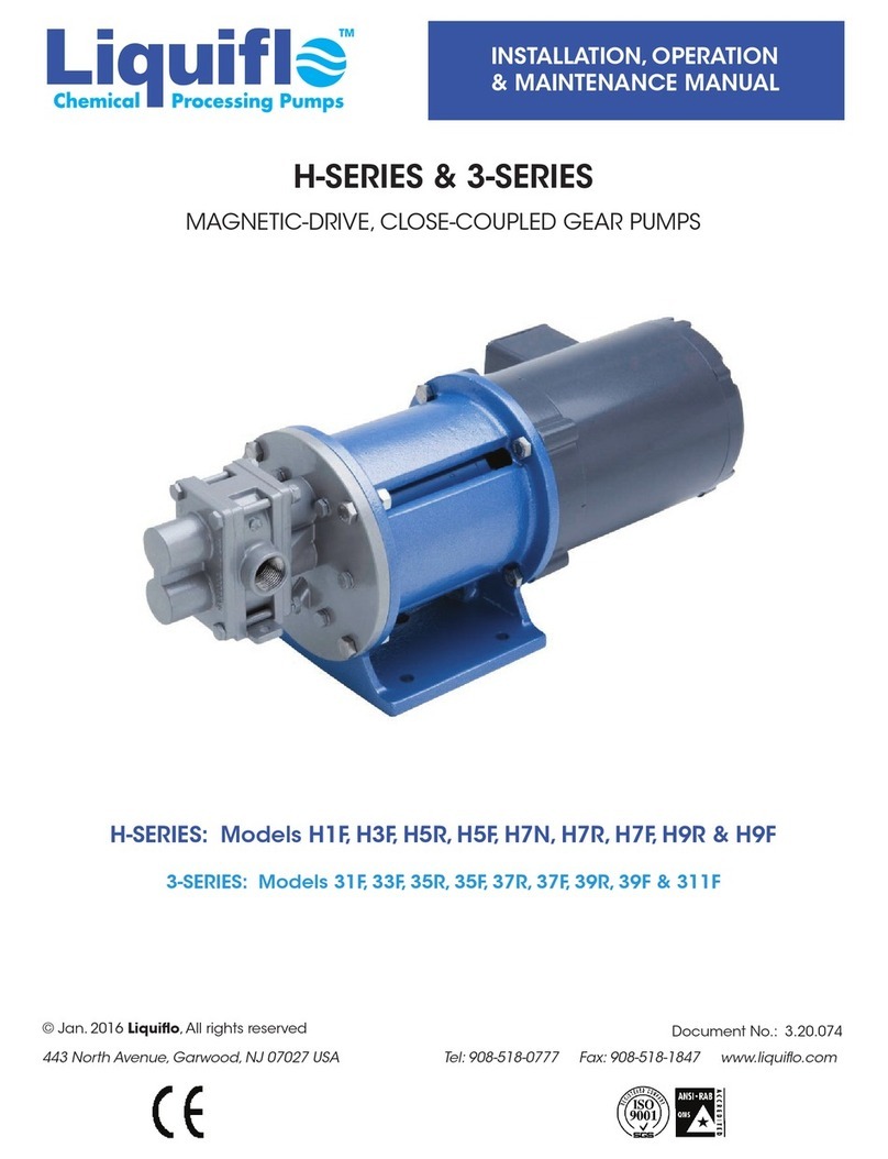
Liquiflo H-Series Instruction manual
Liquiflo
Liquiflo H-Series Owner's manual
Liquiflo
Liquiflo MAX Series User manual
Liquiflo
Liquiflo CENTRY 620 Series Instruction manual
Liquiflo
Liquiflo FTS400 Series Setup guide
Liquiflo
Liquiflo FTS300 Series Setup guide
Liquiflo
Liquiflo FTS Series Setup guide
Popular Water Pump manuals by other brands
Atlas Copco
Atlas Copco DZS 065V Instruction book
Basement Sentry
Basement Sentry 115V instructions

Teral
Teral VKA-e manual

Harvest TEC
Harvest TEC 9214 owner's manual

Hydronic
Hydronic P825 Instructions for installation, use and maintenance manual

IWAKI AMERICA
IWAKI AMERICA Walchem EWN-Y Quick start programming guide
