2Installation and Setup
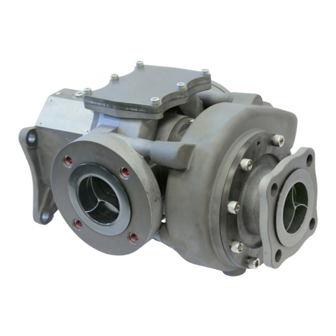
Liquiflo FTS Transfer Pump User Manual
Series No. FTS400
8
Piping guidelines
•All piping MUST be independently supported, and MUST not rely
on the Transfer Pump for support.
•If there is no bypass valve option on your Transfer Pump, you
MUST provide a bypass valve in the process piping on any
discharge side of the Transfer Pump; since the Transfer Pump is
reversible, this may be on both sides of the Transfer Pump
depending on your application. The bypass return MUST be
routed back to the tank and not back to the suction side of the
Transfer Pump; otherwise, an over-temperature condition may be
created in the pumping fluid which would not be detected during
bypass operation.
•For best performance, allow for at least five straight-pipe
diameters free of any bends or valves at any Transfer Pump inlet;
since the Transfer Pump is reversible, this may be on both sides
of the Transfer Pump depending on your application.
•If there is more than one Transfer Pump installed on the same
fluid source, ensure that each Transfer Pump has an independent
suction line to the fluid source.
•Install appropriate isolation valves in the process piping around
the Transfer Pump so that it may be properly drained and/or
removed for service. Size the valves in accordance with the
process piping –valves that are too small will reduce Transfer
Pump performance.
•Ensure that all piping and joints are free of leaks, including
vacuum leaks which may ingest air and reduce pump
performance.
•It is good practice to minimize both the major and minor pressure
losses in the piping system. To do so, minimize the total number
of elbow fittings, valves, and pipe bends; keep the length of the
total piping system as short as is practical; and use an
appropriately large diameter pipe size with regard to the total
length of piping. The user’s qualified personnel is responsible for
calculating the appropriate pipe diameter for the required pipe
length, system height, pumping fluid, and flow requirements. See
Pump Data Package for information on the Transfer Pump’s
performance.
• It is the responsibility of the user’s qualified personnel to assess
the need for filtration in the pumping application. The Transfer
Pump should be installed with a 300-micron filter or finer. Keep in
mind that since the pump is reversible, you may need to install a
filter on both sides of the Transfer Pump, depending on your
application. When any filter is installed, you should monitor the
filter for life to make sure it does not become clogged during
operation, as clogged filters will significantly reduce pumping
performance. Filters that are especially fine will negatively impact
pumping performance even when new.
•For assistance with pipe sizing, system layout, and valve or filter
selection, contact Liquiflo FTS Application Support; see page 3 of
this manual for contact information.
CAUTION
Ensure that the installation has
adequate Net Positive Suction
Head Available (NPSH) for the
fluid to be pumped. See Pump
Data Package. For assistance
with calculating appropriate
NPSHA, contact Liquiflo FTS
Application Support; see page 3
of this manual for contact
information.
CAUTION
If your Transfer Pump does not
include the bypass valve option,
bypass valve(s) MUST be
installed in your process piping.
A bypass valve is REQUIRED
for each flow direction in which
the pump will be operated.
CAUTION
It is the responsibility of the
user's qualified personnel to
appropriately implement
grounding connections for the
fluid plumbing if the application
requires it. THE ANODIZED
COATING OF THE PUMP
HEAD PREVENTS THE PUMP
HOUSING FROM BEING
GROUNDED. The user should
install a grounding strap
between the inlet and outlet pipe
flanges if the application
requires it. For more information
or assistance with determining
grounding requirements, contact
Liquiflo FTS Application
Support; see page 3 of this
manual for contact information.


