LisnaWaters LWST User manual

WITH THE CUSTOMER
INSTALLATION
AND OPERATING
MANUAL
INSTALLERS PLEASE NOTE, THESE
INSTRUCTIONS ARE TO BE LEFT
Technical Support:0333 344 1109
Lisna Waters Steam Shower Whirlpool Bath *
LWST: 1350mm x 1350mm
*image for illustration purposes

2
Thank you for purchasing this product. To guarantee the product delivers a long service life, please
tted and used in accordance with the instructions contained in this booklet.
Please check that the boxes contain all the items listed below, and report to us any parts
that are missing or damaged prior to assembly and within 48 hours of receipt. Damages
ed to us after this time will be chargeable.
CAREFULLY CHECK THE PRODUCT IS AS ORDERED: CORRECT SIZE AND COLOUR OPTION BEFORE YOU
COMMENCE ANY OF THE INSTALLATION PROCESS
oor where the shower is to be located is smooth, level and able to support
the weight of the product when in use.
tters will invalidate your warranty.
Please ensure that all connections are water tight, safe and insulated (where applicable) as the unit has
connections that are made for transport purposes only and are not fully tightened.
Pack contents:
tt ed waste and whirlpool system
tt ed body jets
1 x Shower Valve
2 x Braided water supply hoses
2 x White rear glass framed, white glass panels (marked left and right)
2 x Clear glass, curved doors
at) clear glass side panes.
2 x Silver curved front frame pieces
2 x Silver upright pieces
tt ed)
1 x White Acrylic ceiling inc. speaker, fan, lights and ozone unit
1 x Hand shower, riser bar and chrome hos xings
xings
1 x Magnetic door seals (pair)
4 x Flapped door seals
2 x U Seals
8 x Twin wheels, shower door rollers.
8 x Door roller stoppers
2 x Chrome seldnahrooddehsin
Fixing screws
Refer also to contents list with images on the next pages.

3
Product Contents List with Images
Important Notice
Before you Begin
Assembly
Fitting the Shower Valve
Leveling and Fitting the Tub
Fixing the rear panels
Central Tower Installation
Front Frame Assembly
Installing Fixed Side Glass Panels
Glass Retaining Clips
Shower Ceiling
Temperature Sensor
Runner Wheels
Door Handles
Overhead Shower Fitting
USB Connector
Hand shower and Riser installation
Fixing and Assembly of Glass Shelf
The Shower Valve Connections
Door Seals
Water Connections
Schematic Water and Electrics Diagram
Electrical Connections
Sealing the Shower
Final Testing
Completion
Valve Operation
Electronic Control Panel
Bluetooth Pairing
Safety Precautions
Whirlpool Operation
Cleaning and thirds party product use
Additional information and help
Thermostatic Cartridge
Contents

4
Below is a list of the parts you should have received for the installation of your shower. Please note that
tted in place, such as the monsoon shower head, etc. Please note, the design
er the same or greater functionality.
Lisna Waters Steam and Whirlpool Shower Contents
1
2
3
4
5
67
10
8
9

1. Tub Base with waste assembly and exible waste pipe
if-erpmetsysdnapmuplooplrihW.dettif-erp tted.
2. Two straight metal sections and two curved rail sections
nish (Front Frame).
3. Thermostatic shower valve and 2 braided hoses.
Monsoon maybe included)
ttings.
6. Two Long Flapped seals and two slightly shorter, plus a
pair of Magnetic door seals.
7. Tower with and Body Jets electronic control panel.
at clear glass side pieces.
er in appearance). (Fits into Pre-cut Hole in Ceailing)
11. Two white glass, frames rear panels.
xings.
xing screws and cover caps. (May Be Pre-Fitted)
14. Two pairs of door handles.
xings.
(quick release) cam wheels. (May Be Pre Fitted)
12
14
15
11
13
Please check you have all these parts and they
are in a condition suitable to install BEFORE you
commence installation. We accept no responsibility
for delays due to waiting for replacement to arrive.
16
5
16

6
IMPORTANT NOTICE
tting this product please read and understand the following:
By commencing testing and installation of the unit you are agreeing to the Terms and Conditions
set out by us and copies are available by contacting us by telephone (details on the cover of this
manual).
You are required to ensure the purchased product dimensions allows for ease of passage to the
intended installation area.
Regarding weight tolerances of installation area, it is advisable to contact a builder or refer to
oor support.
1. It is important that you ensure that your purchase has been delivered undamaged. You are required to
check the contents and report any damage that you feel needs repairing or replacing within 48hrs of
receipt of goods. Items reported damaged after this time WILL be chargeable.
ed specialist. The product requires connection to
ed electrician.
3. We are a supply only company. If you report to us any damage we will send replacements or solutions to
remedy the problem described. We endeavor to fully understand th rst by asking a series of
questions and then propose the solution. We may even ask for digital images to be sent via email to assist
the process.
tter
fully tests the unit upon completion and attends to any leaks and faults before he leaves.
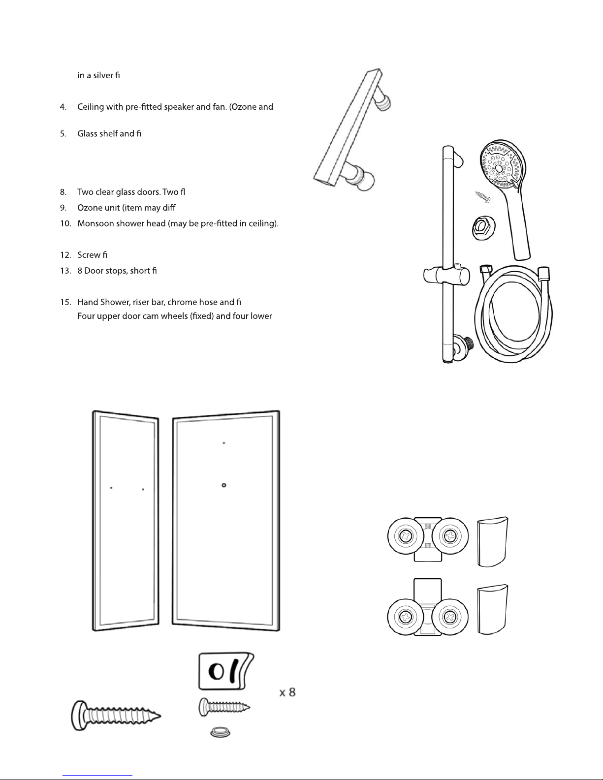
tted for
transport purposes and need to be properly sealed and tightened before use. During transportation
some connections can become dislodged and therefore break any watertight seal, you are required to
x accordingly.
6. tter until you have inspected the unit. We cannot be held responsible for delays
7. We cannot be held liable for inconvenience caused due to lack of bathing facilities caused by any delay in
receiving your product or whilst awaiting parts.
8. Regarding our sales and technical support: We know our products and their requirements, but we are not
suitability of the product with a professional body. It is the customer responsibility to ensure the product
t for purpose.
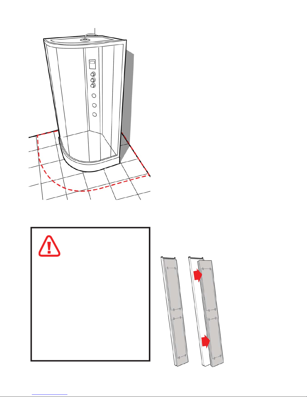
The best advice we can oer our customers when they ask “what is the best way to build this” is to follow the
instructions and perform a dry run to ensure you are condent with the build and you understand fully how
the unit is assembled. When we use the term “DRY RUN”this means you do not silicone anything, just simply
construct the shower, align, drill and screw everything together. Once you are happy with the build take the
unit apart and carry out the full installation, using your silicone sealer at all points outlined in the manual.

7
Before you begin
Tools needed to assemble this shower cabin:
Electric screwdriver with a selection of heads, regular screwdrivers, pipe grips, spanners, spirit level, sharp
knife and rubber mallet. Connection of the electrical supply and plumbing may require additional tools.
There is a drill bit supplied with the kit, to allow either widening of holes or drilling new holes which you
feel cannot be located during construction.
Water requirements
This shower requires two water supplies (1 x hot and 1 x cold) tested to be between 1 and 3 bar, with
a ow rate over 7.5 litres per minute.
NOTE: We recommend water pressures over 2 bar to achieve optimum showering results.
Gravity Fed systems
If yo tting a shower Pump is recommended. Fitting a Twin Impeller
Shower pump rated over 2 bar is necessary as a minimum. Shower pumps MUST be properly sited,
installed and commissioned. Incorrectly installed shower pumps will cause adver acts to your
showering and bathing resulting in pulsing or starting and stopping of the pump. If a pump is installed,
a separate Mains Cold supply tted and directed to supply the Steam Generator separately
(bypassing the pump).
Isolating Valves
Whilst not a requirement
en the water supply to the shower when not in use (for example going away on
holiday). Additionally isolating valves makes service checks easier than locating the house stop cock.
Electrical
This model requires an electrical supply, this MUST be in the form of an ISOLATED FUSED SPUR. It is
t this shower to a plug socket in a Bathroom environment. The product
tted for testing purposes only and should be removed to
complete the install.
tting these as it

8
Assembly
Do not t the shower into locations where you do
not have at least 40cm access all around the cabin
both for installation and for future service access.
We advise you do to t sinks, toilets etc that restrict
access behind the shower.
You must ensure you can slide the cabin away from
the wall/corner for service access.
Smooth and level walls and oor are required for
ideal installation conditions. Avoid carpet or vinyl
oors.
Please ensure you have correctly water tested the
tub before you continue.
NOTE: The base and roof will have a protective lm
that must be carefully removed before assembly.
Please inspect all parts carefully before
assembly.
BY COMMENCING ASSEMBLY OF THIS SHOWER
YOU ACCEPT THAT THE PARTS HAVE ALL BEEN
CHECKED AND ARE UNDAMAGED.
This product is fitted with
toughened safety glass. The
glass is stronger than regular
glass and if it breaks it will form
small pieces of cubed glass, not
dangerous shards of glass. These small
pieces are still sharp, so care must be
taken to handle broken glass with care.
If the glass is put under stress or is chipped
it will break.
DO NOT ALLOW THE GLASS TO IMPACTED
HARD SURFACES OR OBJECTS AS
THIS MAY CHIP/WEAKEN THE GLASS.
WEAKENED GLASS THAT IS CHIPPED OR
UNDER TENSION MAY SHATTER AT ANY
TIME, NOT ALWAYS IMMEDIATELY.
REMOVE THE WHITE PLASTIC COVER ON THE
BACK OF THE TOWER PANEL
Fitted to the rear
of the tower panel
is a white plastic
protective cover.
This part is tted to
protect the valve
and pipes during
transport.
REMOVE and
DISPOSE of this part
as it is not needed.

9
1. FITTING THE SHOWER VALVE
The Thermostatic Shower Valve will need
to be fitted into the central tower panel
into the three pre-drilled, vertical holes
available for it.
First remove the 3 Chrome Dials from the
valve.
The Selector Dial and ON/O Dial are
removed by unscrewing the Chrome Lug
on the side. Once removed this should also
come free with the threaded grub screw part
in place, so the dial will now pull o.
The Temperature Dial has a small silver cap
on the opposite side to the Lug. Remove
this cap and insert a 2.5mm Allen Key inside
to the grub screw. Turn a small amount to
loosen (not remove) and then pull the dial
away.
Next unscrew each of the Chrome Dial
plates.
Now position the valve from the rear of the
central panel to align with the holes and
push through the holes.
Re-t each of the Chrome Dial Plates from the
front of the panel. This will now hold the valve in
position.
Adjustment can be made to the rear nuts to allow
the valve to be seated correctly against the panel.
Now you can re-t each of the chrome dials,
remembering to t the lower (thermostatic control
dial) on the lower most position.
Now the valve is in position and tight you can
t the two WRAS approved, Braided hoses to
the water inlets at the bottom of the valve in
preparation for connecting to water at a later
stage.
Connect also the silver/grey hose from the
overhead shower that is pre-tted to the upper
part of the central panel. Ensure this connection is
watertight.

10
2. LEVELING AND FITTING THE TUB
Remove the protective lm covering the tub base.
Connect the soil pipe, trap and any couplings to the exible waste under the tub. You may choose to
t either a HEPV0 trap with the appropriate couplings or choose to t a McAlpine ST28M coupling to a
McAlpine 28-NRV trap.
Position the tub base in what will be its nal location and adjust the feet until the base is level. You can
raise/lower the feet under the tub and with a spirit level laid across the tub, ensure the tub is level.
Now ll the base with some water and check that the water ows adequately to the plug and exits
satisfactorily. If the water does not ow to the plug fully, then you will need to increase the fall on the
tray by adjusting the legs. If the water does not exit the waste section fast enough, then ensure there is
suitable fall in the waste pipe and/or no blockage or kinks in the pipe work.
Check and attend to any leaks.
Now slide the tub away from the wall to allow access all around the shower as you assemble.
This product is freestanding so you do not need to x the feet to the oor.

11
3. FIXING REAR GLASS PANELS
The two rear, framed glass panels are labeled LEFT and RIGHT as you would face the shower. Position
xing holes is positioned to the rear.
with the screws only, so you MUST support them until the next stage.
rst to ensure all screws
nd their correct position before then tightening them all fully.
A bead of Sealant can be applied along
the line where the rear glass panels will
be placed.
20mm screws
2 Persons Required Section

12
4. CENTRAL TOWER PANEL
er up the central tower panel from the inside of
the cabin between the two rear panels.
Moving to the rear of the cabin, adjust the Tower
Panel to align the holes in the long vertical edge of
the tower with those in the back panels.
The Tower and back Panels are joined using the
t the
screws, ensuring all screws can locate correctly -
this allows movement of the parts to do so. Once
all screw are located successfully, tighten them
fully.
If necessary, holes can be drilled or adjusted using
a small 3mm drill bit. 20mm screws
Remember to remove any excess sealant once the
panels have been seated into position.
There may be 5 pre-drilled holes per side

13
5. FRONT FRAME
Locate the two silver coloured upright frame
sections and the two curved frame rail sections.
You will need the 8 x LONG screws to join these
sections together.
The upper rail is deeper height than the lower rail.
Align the upright with two holes in, to the upper
curved rail. The screws pass through the holes in
the side of the upright and fasten into the curved
rail as shown in the digram below.
A power driver is advised for this process.
DO NOT FULLY TIGHTEN THE SCREWS -
ALLOW SOME MOVEMENT IN THE FRAME FOR
INSTALLING THE FIXED GLASS
Repeat the process on the other upright.
Finally, join the lower curved rail to the other ends
of the uprights using the 60mm screws.
You now have completed the front frame assembly.

14
6. INSTALLING THE FIXED SIDE GLASS PANELS
Remove the SEAL TRIM that is located in the inside
edge of the lower curved rail. It is held in position
by two screws. Remove this trim to help you t the
xed side glass panels. You will need to re-attach it
after the glass is tted.
Locate the two xed glass panels. These are
dierent from the doors as they do NOT have any
holes pre-drilled.
Locate the two U shaped rubber seals.
Take one of the U shaped seals and t over one
long edge of the xed glass panels. Trim any excess
leaving it running the full length.
Now position this glass panel up to the frame
pushing the long edge of the glass into the upright
of the frame until FULL bedded into the frame
upright.
This MUST be done from the inside of the frame.
The glass will sit within a lip on the inner surface of
the curved rail both top and bottom.
DO NOT HIT GLASS WITH HARD
OBJECTS TO PUSH INTO THE FRAME.
Repeat this process on the other glass panel.

15
Now both glass panels are fully inserted into the
uprights you can tighten up the four corners of the
silver framework which will not hold the glass in
position.
t the Retaining Clips to hold the
the inside of the upper and lower rails, mark the
x a screw to
hold the clip in place. Repeat top and bottom on
CAUTION WHEN DRILLING - ONLY DRILL
THROUGH THE INNER SINGLE LAYER OF FRAME
x the SEAL TRIM back on the inside of the
lower curved frame.
7. GLASS RETAINING CLIPS
8. FITTING THE FRONT FRAME
Place the completed front frame section onto the
front of the shower tub and align the uprights of
the frame with the rear glass panels so that the
From behind the rear glass panel, locate each
screw hole into the front frame screw through the
lip of the white framework of the rear glass panels
into the frame to secure in place. (8 x short 16mm
screws)
The help ease this process, you may need to use
the supplied drill bit in the holes to ensure they are
wide enough and clear.
There may be 5 pre-drilled holes per side
if so use 5 small 16mm screws

16
9. SHOWER CEILING
lm from the roof/ceiling.
t the monsoon rain
shower head into the centre of the roof. It is held
in place with a retaining nut located on the outer/
upper face of the roof.
tted. Ensure
all the cables are unraveled to enable location and
connection at a later stage.
The Ozone unit is supplied separately and will
the main body of the ozone. Position the white
unit on the up (outside) of the roof and fasten in
place by screwing the chrome end into it.
The Ozone will be located over the hole in the roof
towards the back corner.
You can now place the ceiling onto the shower. The
front will sit behind the front silver frame and the
rear will rest on the top of the rear glass panels.
xed in position at the REAR ONLY by
screwing up through the re-drilled holes in the rear
panel, into the ceiling. Fixing requires 3 of the short
Now ensure all the cables for the ozone, light, fan
and speaker are hanging down the back of the
shower ready to connect.
REPLACING THE CEILING LIGHT
Your shower is tted with an LED ‘Halo’ Ring light. This light should provide a long service life if
used correctly. If you need to change your ceiling light once the shower is installed, please turn
o the water to the shower rst, then disconnect the water supply pipe to the monsoon rain
shower on the roof of the shower. Loosen the retaining bolt for the monsoon and lower into the
shower. (we suggest you have another person inside the shower to hold it from falling).
From inside the shower with the monsoon removed, the light di user cover will also come free.
Disconnect the power cable to the light on the roof of the shower, unscrew the retaining screws
for the light and remove.
To t the replacement, simply reverse the process.
er in shape from this representation
REMOVE PROTECTIVE FILM FROM THE MONSOON
16mm screws, three along each at side of the ceiling

17
11. FITTING THE SHOWER DOOR WHEEL RUNNERS
Locate the pack of 8 twin wheel shower door runners (cams).
erent types provided.
Continued...
10. STEAM TEMPERATURE SENSOR
temperature sensor that monitors the internal
cabin temperature. The temperature is selected
on the control panel. When the internal cabin
ned temperature
it stops steam production until the temperature
falls below, whereupon it re-activates the steam
production again.
the shower. Just below the control panel you will
see a small silver gromit. This is where the head of
the sensor will project into the shower.
From the rear of the shower, locate the black cable
of the temperature sensor. It has a silver tip. Push
the silver tip into the rear of the gromit so that its
x in position
with a small amount of silicone.
May be pre-tted to glass doors

18
(image based on
top cam tting)
To fit each of the cams, first select the appropriate cam for the position on the door:
4 x Push button/Quick release for the lower position on the doors.
4 x Standard non push button for the upper position on doors.
Position the Cam Body on the outside facing side of the door (curve pointing outwards). Place the clear
rubber gasket between the cam body and the glass. The gasket will t into the hole on the glass.
On the inside of the door, position the grey plastic inner cam body, then washer and bolt.
Now tighten the parts together with the bolt until rmly held in place.
DO NOT OVER TIGHTEN AS YOU MAY BREAK THE GLASS
With the cam xed in position, slide on the Chrome nished cover.
Repeat this process of all of the cam wheels.
TO HANG THE DOORS
From inside the shower position the upper wheels into the running tracks on the inside curve of the
upper curved rail and then let the door hand down.
From outside the shower, move the door to what would be a closed position and press the quick release
buttons on the top of the lower cams and move the wheels to t into the lower runner tracks.
Repeat for the other door.

19
12. FITTING THE DOOR HANDLES
Each of the two shower doors requires a pair of
chrome nished door handles to be tted.
Each handle is comprised of several parts. Position
the main handle part on the outside of a door
ensuring the Chrome Washer and a Clear Washer
are positioned also on the outside face over the
thread. Push the threaded ends through the glass.
Next place another clear washer on the threads
and then screw on the two dierent Chrome Knobs
to the inside of the glass door.
Tighten until secure. DO NOT OVER TIGHTEN.
TEST FOR LEAKS
Make sure the connection is tested and
is watertight. You may wish to use some
PTFE tape or other suitable products to
provide the best water tight seal on this
joint.
13. OVERHEAD/MONSOON SHOWER
The overhead shower is fitted into the ceiling from
the inside. The overhead shower first passes
though the light diffuser cover (inside the shower),
so that the threaded end of the overhead shower
passes out through the ceiling. Fit the FIXING NUT
onto the threaded end on top of the ceiling to hold
the shower and diffuser cover securely in place.
Next locatethe water supply hose coming from the
shower valve and identified as being the overhead
water feed. Fit the threaded end of the water
supply hose onto the overhead showers threaded
section and tighten.
REMOVE THE PROTECTIVE FILM ON THE FACE OF
THE MONSOON BEFORE USE.

20
14. HAND SHOWER AND RISER
You are now ready to assemble and connect
the hand shower.
The hand shower comprises of:
Multi function hand shower
Chr
ome nished riser bar
Hand shower holster
Chrome water hose
Rear retaining nut
Fitting screw
The lower part of the riser bar has a threaded water
connection. Position this part through the larger
hole on the rear glass panel.
to hold in place. Secure the upper part of the riser
bar with the screw provided. Tighten both until
secure.
Connect the silver hand shower hose to the lower
part of the riser bar and the other end to the hand
shower head.
At the rear of the shower, locate the grey water
supply hose coming from the shower valve and
connect to the water inlet of the riser bar. Test this
water connection to ensure it is water tight. Using
some PTFE tape or other product may help to
achieve the best watertight connection.
Table of contents
Popular Bathtub manuals by other brands

agape
agape VIEQUES Assembly instructions

Kohler
Kohler K-1259-LA Roughing-In Guide

American Standard
American Standard Reminiscence 2908E parts list

Seima
Seima TONDO INSET installation guide

Signature Hardware
Signature Hardware SITKA 948269 quick start guide

Altair
Altair 51567-BAT-WH-FS MAINTENANCE INSTRUCTIONS MANUAL

American Standard
American Standard Williamsburg Elite 5' Integral Apron Whirlpool... installation instructions

Kohler
Kohler K-99025T owner's manual

Jacuzzi
Jacuzzi LUXURA F946 Specifications

Lyons
Lyons Elite ETLxx663219 Series manual

American Standard
American Standard Colony 2740 Series installation instructions

Kohler
Kohler K-1397-H2 Homeowner's guide