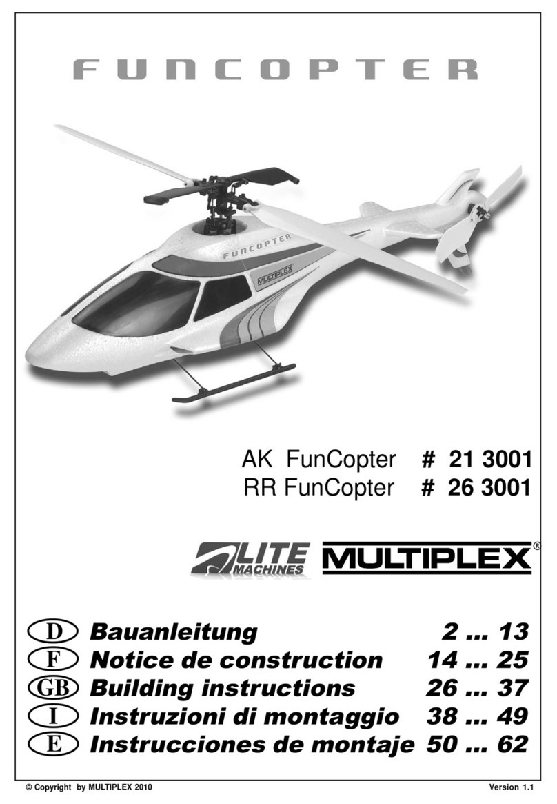
Lite Machines LMH 100 Instructions for use

Acknowledgments
We thank all of those people who helped make Lite Machines Corporation and the
Model 110™ helicopter possible, including our good friend Paul Klusman. The Model
110 Construction Manual and Operator’s Guide were developed and computer
illustrated by Paul Klusman: engineer, test pilot and helicopter guru. We especially
thank Mom and Dad - without their help and constant encouragement we could not
have done this.
David and Paul Arlton
Lite Machines Corporation
Purdue Research Park
1291 Cumberland Avenue
West Lafayette, IN 47906
Tel: (765) 463-0959
Fax: (765) 463-7004
USA
PATENT
NOTICE
Most aspects of the Lite Machines Model 110 helicopter including, but not limited to,
the main rotor, main rotor blades, tail rotor, tail rotor blades, Arlton Subrotor™
stabilizer, Arlton Gyro™ stabilizer, swashplate, fuselage structure and configuration,
radio installation configuration, landing gear, and drive train are either patented (U.S.
5305968, 5597138, 5609312, 5628620, 5749540, 5836545, 5879131, 5906476;
Australia 681287, 686883; Europe 95918276.7-2312, 95932305.6-2312,
96928019.7; France 0605656; Germany 69221307.4; U.K. 0605656), patent
pending or patent applied-for in the United States and in other counties. For
information concerning patents and licensing, please contact Lite Machines
Corporation.
© Copyright Lite Machines Corporation, 1994-1999. All rights reserved.
Revision VP8.2 0699
Construction Manual Acknowledgments
LITE MACHINES

Table of Contents
Introduction
Introduction 1-1
Consumer Warranty.............1-2
Model Helicopter Safety
Model Helicopter
Safety 2-1
Fuel Safety .................2-1
Flight Safety.................2-2
General Safety ...............2-3
Requirements
Requirements 3-1
Radio ....................3-1
Engine and Fuel...............3-1
Field Equipment...............3-2
Building Supplies ..............3-2
General Building Guidelines
General Building
Guidelines 4-1
Friction and Binding .............4-1
Balance of Rotating Assemblies ......4-2
Fastener Identification ...........4-2
Crutch
Crutch 5-1
Canopy
Canopy 6-1
Main Rotor
Main Rotor 7-1
Swashplate
Swashplate 8-1
LITE MACHINES
Construction Manual Table of Contents

Arlton Gyro Stabilizer
Arlton Gyro
Stabilizer 9-1
Tail Boom
Tail Boom 10-1
Engine
Engine 11-1
Final Assembly
Final Assembly 12-1
Radio Installation
Radio Installation 13-1
Pushrods and Radio Adjustment
Pushrods and Radio
Adjustment 14-1
Final Check
Final Check 15-1
Construction Manual Table of Contents
LITE MACHINES

Introduction
The Lite Machines Model 110ähelicopter is the first mass-produced radio controlled
micro helicopter in the world. It is intended as an introductory helicopter for those
modelers intrigued by helicopters and helicopter flight, but unable to justify the
significant investment in time and money required for traditional helicopter models.
The Model 110 can withstand tip-overs and minor crashes with little or no damage.
Many flight skills such as basic hovering, nose-in hovering, low speed maneuvering,
forward and backward flight, and pirouettes can be mastered without busting the
family budget with a larger, more complex machine.
The Model 110 utilizes advanced aerodynamics that enable it to fly on 1/10th of a
horsepower which is roughly the power consumed by a 75 watt light bulb. In comparison,
.30 to .60 size model helicopters use one to two horsepower (10 to 20 times more).
The fixed-pitch main rotor of the Model 110 helicopter combines Subrotorä
technology and free-flapping, foldable rotor blades in a rugged, high lift rotor system
with fewer than half the number of parts found in collective-pitch helicopters. Main
rotor lift is controlled by changing the rotational speed of the main rotor rather than
varying the pitch of the individual rotor blades (such as with “collective-pitch” type
main rotor systems). Fixed-pitch main rotors are substantially simpler than
collective-pitch systems and are ideal for beginners. Collective-pitch main rotors
allow for advanced aerobatics and engine-off autorotation maneuvers that are
typically flown by more experienced pilots.
The tail rotor mechanism of the Model 110 helicopter incorporates a light-weight
Arlton Gyroästabilizer which eliminates the need for an expensive electronic gyro
and extra capacity receiver batteries. The unique central keel fuselage structure is
simple, strong and easy to assemble and repair-afarcryfromthefragile
construction of many electric helicopters.
Designed on modern computer-aided design (CAD) systems and computer-aided
manufacturing (CAM) systems, the structure of the Model 110 helicopter
incorporates eight types of engineering plastics, four aluminum alloys, several high
strength steels, aircraft plywood and multiple protective surface coatings.
Although beginners can successfully build and fly their Model 110, the process can
be made significantly easier with the help of an experienced modeler and instructor
pilot. Lite Machines recommends that all beginners join the Academy of Model
Aeronautics (AMA). The AMA is a non-profit organization that provides services for
modelers. The AMA can help you locate a model aircraft club in your area with an
instructor pilot (you can also check with your local hobby shop). Membership benefits
include a monthly magazine and liability insurance. Many flying clubs require an AMA
modeler’s license to operate a model on their flying field. For information on the AMA
call (765) 287-1256, or write to:
Academy of Model Aeronautics
5151 East Memorial Drive
Muncie, IN 47302
Construction Manual Introduction
LITE MACHINES 1-1

Consumer Warranty
IMPORTANT! Before building this Model 110 helicopter kit, read and fully
understand the following warranty, and review the entire Construction Manual and
Operator’s Guide. By building and/or flying this helicopter you indicate your
acceptance of the following warranty terms and conditions, and further agree to build
and operate this helicopter in a safe and responsible manner.
If you find any term or condition of the warranty unacceptable, or if you feel that this
helicopter is just not suited to you, you may return it to your place of purchase in NEW
and UNUSED condition within thirty (30) days of the date of purchase for a refund of
the purchase price less shipping and handling. Partially assembled kits, and kits with
opened parts packs or missing parts cannot be returned for a refund. Items such as
radios, engines and accessories are warranted separately by their respective
manufacturers and are not warranted by Lite Machines.
Warranty:
1. Lite Machines Corporation warrants to the first consumer Purchaser that the
Model 110 helicopter substantially conforms to its published description when
used as intended as a hobby product, and will be free from defects in materials
and workmanship for a period of 90 days after the date of purchase. Lite
Machines will repair or replace (at its option) any defective part, and supply any
missing part at no charge to the Purchaser within this period. Lite Machines
makes no other warranty, express or implied. This warranty does not apply to
parts damaged by improper assembly, modification, abnormal service or
handling, or crashes.
2. To take advantage of this warranty the Purchaser must provide proof of
purchase, receive a return authorization (RA) number from Lite Machines, and
ship any defective part (at Purchaser’s expense) to Lite Machines for repair or
replacement. Shipments of warranted parts back to Purchaser will be made by
common carrier standard service. Over-night, expedited or priority service
requested by Purchaser will be at Purchaser’s expense.
3. It is the responsibility of the Purchaser to properly assemble, maintain, and
operate this helicopter in accordance with manufacture’s instructions, AMA
(Academy of Model Aeronautics) safety codes, local laws and ordinances, and
COMMON SENSE. It is also the responsibility of the Purchaser to ALWAYS
WEAR APPROPRIATE EYE AND HEARING PROTECTION when operating
this helicopter, and never to operate this helicopter in any way which might
endanger persons or property including the Purchaser. The Purchaser is advised
to carry appropriate liability insurance such as that commonly provided to
modelers by the Academy of Model Aeronautics.
4. THIS WARRANTY SPECIFICALLY EXCLUDES THE IMPLIED WARRANTIES
OF MERCHANTABILITY AND FITNESS FOR A PARTICULAR PURPOSE. The
selection of this helicopter for a particular application or use (beyond
hobby/entertainment) is the sole responsibility of the Purchaser. Any advice
supplied by any representative of Lite Machines pertaining to any particular
application is given freely as an opinion and is not meant to bind Lite Machines or
in any other way modify this warranty. Since Lite Machines has no control over
Construction Manual Introduction
1-2 LITE MACHINES

the assembly or use of this product, and since operation of a helicopter is
affected by various conditions such as engine power, local elevation and air
temperature, Lite Machines cannot guarantee specific performance figures.
5. Notwithstanding the paragraph above, this warranty is in addition to whatever
implied warranties may be granted to the Purchaser by law. To the extent
permitted by law, all implied warranties, including the warranties of
merchantability and fitness for a particular purpose, are limited to a period of one
(1) year from the date of purchase. Some states do not allow limitations on how
long an implied warranty lasts, so the above limitation may not apply.
6. This warranty shall be the sole and exclusive remedy available to the Purchaser.
Correction of defects, in the manner and for the period of time specified above,
shall constitute complete fulfillment of all liabilities and responsibilities of Lite
Machines to the Purchaser, and shall constitute full satisfaction of all claims,
whether based on contract, negligence, strict liability or otherwise. Lite Machines
shall not be liable for any costs or expenses incurred in the replacement of any
defective or non-conforming parts, and IN NO EVENT SHALL LITE MACHINES
BE LIABLE FOR INCIDENTAL OR CONSEQUENTIAL DAMAGES, OR ANY
DAMAGES DUE TO THE USE OR INABILITY TO USE THIS PRODUCT. Lite
Machines shall not be liable, or in any way responsible, for any damages related
to modifications, repairs, attempted repairs, or crashes. IN NO EVENT SHALL
LITE MACHINES’ OBLIGATIONS TO THE PURCHASER EXCEED THE
ORIGINAL PURCHASE PRICE PAID BY THE PURCHASER TO LITE
MACHINES.
7. Some states do not allow exclusion of incidental or consequential damages, so
the above exclusion may not apply. This warranty gives the Purchaser specific
legal rights. The Purchaser may also have other rights which vary from state to
state.
8. This warranty shall be governed by the laws of the State of Indiana, USA, and any
action related to this warranty shall be brought within the jurisdiction and
boundaries of the state of Indiana, county of Tippecanoe.
9. No modification or amendment to this warranty will be effective unless reduced to
writing and signed by an authorized representative of Lite Machines Corporation.
If you do not understand any aspect of this warranty you may contact Lite Machines
for clarification. IF YOU DO NOT AGREE WITH ANY ASPECT OF THIS
WARRANTY, RETURN YOUR UNASSEMBLED HELICOPTER TO YOUR PLACE
OF PURCHASE FOR A REFUND.
Lite Machines believes that information contained within its published materials is
accurate as of the date of publication and is not responsible for inadvertent errors or
omissions. Lite Machines reserves the right to make changes and improvements in
its products without notice.
Construction Manual Introduction
LITE MACHINES 1-3

Model Helicopter Safety
This section contains important safety information regarding proper handling of
model-engine fuel and operation of the Lite Machines Model 110 helicopter.
Fuel Safety
1. Use ONLY commercial fuel developed for model engine use. NEVER USE
GASOLINE, DIESEL, OR ANY OTHER FUEL! These fuels will ruin model
engines, and can explode and burn causing injury to YOU and OTHERS.
2. DO NOT OPERATE MODEL ENGINES INDOORS! Hot engine parts and
exhaust could ignite carpeting, drapery or furniture. Engine exhaust also
contains large amounts of unburned oil that will soil interior furnishings.
3. Never fuel or prime with the glow-plug battery connected to the engine. Sparks
from the electrical connection could start a fuel fire.
4. Never fuel, prime, or operate your model while smoking.
5. Store fuel in a cool dry place protected from sunlight and from potential ignition
sources (anything burning, or anything that could start a fire if exposed to fuel
such as shorting or sparking battery terminals or the furnace in your home).
6. Remove excess fuel from your model with a cloth after refueling or priming. Raw
fuel can damage paint and is a potential fire source.
7. Do not store fuel in your model.
8. Fuel is poisonous and can cause death or blindness if swallowed. If swallowed,
induce vomiting and call for medical assistance immediately.
9. Fuel is an eye irritant. In case of contact with eyes, flush thoroughly with water.
10. Raw fuel will damage certain types of plastic. Prescription plastic lenses and the
clear plastic commonly used on radio transmitter meters will be damaged if
exposed to raw fuel (such as droplets sprayed from the engine during starting).
Wipe off immediately using spray window cleaner.
IF FIRE SHOULD OCCUR:
1. Model fuel burns with a nearly INVISIBLE FLAME, BE VERY CAREFUL!
2. Use a fire extinguisher, or smother fire with a CLEAN, heavy cloth. If fire persists,
GET AWAY! Better to lose the model than risk severe burns.
Construction Manual Model Helicopter Safety
LITE MACHINES 2-1

Flight Safety
1. ALWAYS WEAR APPROPRIATE EYE PROTECTION WHEN OPERATING
YOUR MODEL. Fuel droplets, loose parts, and airborne debris ejected from your
model could cause serious injury or blindness. Select comfortable, well-fitting
eye wear with high-impact resistance such as shop glasses. Prescription
glasses made of glass are dangerous because they could shatter if struck
sharply.
2. ALWAYS WEAR APPROPRIATE HEARING PROTECTION WHEN
OPERATING YOUR ENGINE. Many car, airplane and helicopter modelers
ignore the sound produced by the engines on their models. High volumes and
high frequencies produced by model engines can damage hearing. This damage
can be cumulative. Ear-phone and ear-plug style hearing protectors (sold in
sporting goods stores in the gun section) are inexpensive and effective at
reducing the most damaging and annoying qualities of engine sound. Once your
model is started and flying, hearing protection is usually not necessary.
3. NEVER STAND OR PLACE YOUR EYES OR FACE IN-LINE WITH ROTATING
MAIN ROTOR OR TAIL ROTOR BLADES. Loose parts or debris thrown outward
from rotating rotors could cause injury or blindness.
4. NEVER, EVER FLY NEAR OR OVER PEOPLE. Always keep your model at a
safe distance from yourself and spectators.
5. Use only those model engines designed specifically for the Model 110 helicopter.
Use of more powerful engines (such as racing engines) is potentially dangerous
and will void all warranties.
6. Do not use fuel containing more than 35% nitromethane. The added power and
heat of high nitro fuels can damage both the engine and your model.
7. Never allow main rotor speed to exceed 2000 RPM (as by operating with blade
pitch set too low, or using a high powered engine with high nitro fuel). Rotor parts
could separate from the rotor head and cause serious injury or property damage.
Very high speeds can also damage the engine.
8. Fly only at approved flying fields or in open areas away from people and property.
Do not fly in residential areas.
9. Before turning on your radio, ensure that your radio frequency is not already in
use. Flying clubs have organized frequency sharing procedures.
10. Range check your radio prior to the first flight of each day. If your range check is
lower than normal, do not fly.
11. Prior to the first flight of each day, check all mechanics for smooth, unobstructed
operation. Before the main rotors reach flying speed, gently move all flight
controls and confirm proper function. Do not fly if anything is out of the ordinary.
12. Check for hidden damage after crashing, and replace any damaged
components.
13. Beginners should have the main rotors tracked, and model adjusted for flight by
an experienced modeler.
Construction Manual Model Helicopter Safety
2-2 LITE MACHINES

General Safety
1. Periodically check tightness off all bolts, nuts, set screws and pins. Loose parts
could be ejected from your model causing injury, or causing the model to crash.
2. Replace broken or worn components with original parts only. It is important to
locate and understand the cause of failure (including pilot error) to prevent
recurring problems.
3. Never modify any part of the main rotor or tail rotor systems or drive train.
Modifications could lead to part failure.
4. Always replace the main and tail rotor blades in sets if damaged.
5. Do not store your model in direct sunlight. Prolonged exposure to ultraviolet light
can weaken some types of plastics.
6. When flying in very cold conditions be aware that metals and plastics (even
flexible ones) can become brittle and break or shatter.
7. Keep your model, radio and field equipment clean and in good repair. While
cleaning and maintaining your model you can often find and fix potential
problems before they occur (such as loose or damaged parts).
Construction Manual Model Helicopter Safety
LITE MACHINES 2-3

Requirements
This section lists the equipment, tools and materials needed to assemble and
operate the Lite Machines Model 110™ helicopter. Note that a specialized helicopter
radio and electronic gyro are not required. Although helicopter radios may be used,
they are usually more expensive than airplane radios and do not appreciably improve
the flying qualities of the Model 110 helicopter.
Federal law requires that radio controlled model aircraft use specific radio
frequencies. Check with your hobby dealer or local club to find a radio frequency
within the appropriate band that is not popular with other fliers in your area (since two
aircraft cannot fly on the same frequency simultaneously), and is not subject to local
interference (some phone pagers may cause interference).
Radio
1. Standard four (4) channel airplane-style transmitter (Hitec Focus 4H Micro,
Futaba Attack, Airtronics Vanguard,JRF400 etc.. Most radio manufacturers
normally supply servo mounting hardware and extra servo control arms.)
2. Four (4) MICRO servos (Hitec HS-80/HS-81, Futaba 3101, Airtronics 94501,JR
341, etc.)
3. 250 mAh to 600 mAh battery pack, flat style
4. 2-piece Dean’s antenna (This short whip-style antenna replaces the long wire
antenna on the radio receiver. Long antennas used on airplanes get tangled in
the rotor blades of the Model 110 helicopter.)
5. Servo mounting hardware (if not supplied by radio manufacturer)
6. 3" x 6" x 1/4" latex foam rubber sheet (to protect the receiver from vibration and
minimize crash damage)
7. Two small plastic bags (to protect the receiver and battery from dirt and oil)
8. Newspaper rubber bands (to secure radio battery and receiver)
Engine and Fuel
1. Norvel Vmax-6 helicopter engine (The Vmax-6 has special cylinder porting and a
carburetor venturi sized for easier starting. Do not use super-revving racing
engines such as the Norvel AME. Racing engines are too powerful and run too
fast for the Model 110 helicopter, and can dangerously over-drive the rotor
system. The Model 110 helicopter is not warranted for use with any engines
except for the Norvel Vmax-6).
2. Lite Machines SpiraLite Speed™ or Norvel Freedom XL glowplug
Construction Manual Requirements
LITE MACHINES 3-1

3. Small fuel filter (Do not fly without a fuel filter or pre-filtered fuel. A clogged
carburetor jet can cause the engine to stop in flight.)
4. Commercial model engine fuel containing castor oil or a castor/synthetic oil
blend and 15% to 25% nitro methane such as Norvel NVX or Morgan’s Omega
fuels (Do not use Morgan’s Cool Power fuel which contains only synthetic
lubricant. Some synthetic oils break down at high temperatures, and their use
may lead to engine damage. Also, do not use Byron’s or Powermaster fuels
made for large engines. These fuels have additives that will foul the glow plug on
the Vmax-6. If you like Byron’s fuels, use Byron’s 1/2A Blend. Use lower nitro fuel
when flying at elevations near sea level, and higher nitro fuel at high elevations. A
pint is enough for about 8 flights.)
Field Equipment
1. Electric starter with reversible rubber starter cone
2. 12 volt battery and charger for electric starter
3. Lite Machines Lil’ Squeezer fuel system or fuel pump (Do not use a rubber fuel
bulb or a syringe with a rubber plunger to transfer fuel because the rubber will
contaminate the fuel and foul the glow plug on Norvel engines)
4. DuBro Kwik-Klip glow plug starter
5. Paper towels and spray cleaner (Model fuel contains lubricating oil which is
exhausted by the engine and coats everything. Fantastik all purpose cleaner
works well as an oil remover.)
Building Supplies
1. Thin cyanoacrylate (CA) glue, ½ oz. (Fast setting thin CA glue is used for quickly
joining wood parts and sometimes finger tips. Use CA glue specially formulated
for hobby applications, such as Instant Jet by Carl Goldberg Models. Do not use
regular Super Glue purchased at a grocery store.)
2. Thick cyanoacrylate (CA) glue, ½ oz. (Slow setting thick CA glue can fill small
gaps and form fillets, and allows time to reposition parts after gluing. Super Jet
medium viscosity by Carl Goldberg Models works well.)
3. CA accelerator (Accelerator hardens CA glues instantly)
4. Liquid thread-lock for securing bolts and set screws (Use only anaerobic thread
locking compound such as Devcon and Loctite brands made for metal screws.
Loctite “blue” formula works well. Do not use Loctite “red” formula because it is
almost permanent and makes setscrew removal and adjustment difficult.)
5. Synthetic grease (Lite Lube Grease is recommended, 1/4 oz will last for many
years)
6. Lube oil with needle oiling tube (Lite Lube Heavy Oil is recommended, 14.9 ml will
last for many years.)
Construction Manual Requirements
3-2 LITE MACHINES

7. Masking tape
8. X-Acto knife with #11 blades
9. Needle-nose pliers
10. Standard hand pliers
11. Soldering iron and solder (borrow these from a friend if you don’t have them)
12. Pencil
13. English ruler (Queen Elizabeth)
14. Paper clip (for radio switch extension)
15. Scissors
16. Newspaper rubber bands (to secure radio receiver and battery)
17. Electric drill and drill bits
18. Hammer (A hammer is required to gently tap pins into some plastic parts. It is also
useful when things go hopelessly wrong and instant gratification is desired.)
19. Small phillips screwdrivers (for installing radio components, jeweler’s style
works best)
20. Small flat-head screwdriver (for adjusting needle valve on engine)
21. Fuel-proof dope or paint (Dope is best for fuel-proofing wood parts because it
soaks into wood, dries quickly and is harder than most paints. Buy one large
spray can, or one small jar of color and one jar of dope thinner. Dark colors cover
wood grain and hide dirt and oil better than light colors.)
22. ½" camel hair paint brush (if necessary for applying dope)
23. Building surface (a 4 foot by 3 foot flat, uncluttered work surface is sufficient)
Construction Manual Requirements
LITE MACHINES 3-3

General Building Guidelines
Assembling a model helicopter can be a lot of fun. As you build your Lite Machines
Model 110 helicopter you will observe the function of each part and subassembly,
and develop a feel for mechanical systems in general. It is important to build your own
Model 110 so that you know how to maintain and repair it. For more technical
information on how helicopters work, refer to the How Helicopters Work section of the
Operator’s Guide.
Most parts of the Model 110 are designed to assemble in only one way, so assembly
is easy. In some cases, however, parts can be assembled upside-down or
backwards. As much as possible, the instructions will warn you about incorrect
assembly, so read each assembly instruction entirely and study the drawings before
performing each assembly step. When you have completed an assembly step, mark
the check-off box by the step number to keep track of your progress.
Review this entire Model 110 Construction Manual and the Model 110 Operator’s
Guide before starting assembly. The beginning of this Construction Manual contains
a list of required tools and materials. Follow all building steps carefully, and make no
modifications or “improvements”. Modifications can reduce performance or lead to
part failure. Remember, proper assembly and safe operation of your Model 110
helicopter are your responsibilities.
Friction and Binding
For the best flight performance, it is important that all mechanical linkages move very
freely. The servos in the Model 110 must actuate several interconnected pushrods,
control arms and ball-links to control the main rotor and tail rotor. Even small amounts
of friction or binding in the linkages can affect flight performance. Friction and binding
often cause problems that are difficult to diagnose, especially for beginners.
Fig. 4-1 shows a simplified linkage system with a servo and several interconnected
linkages. Tight ball-links, rubbing pushrods, dragging control arms and jammed parts
are all sources of friction and binding. Even if each link produces only a small amount
of friction, the total friction produced by a long chain of links can be substantial. This
friction can stall the servo, or cause it to perform erratically. Friction and binding can
also prevent small servo movements from reaching the main rotor or tail rotor where
they are needed for precise control when hovering.
In addition to link friction, molding “flash” (the thin plastic ridge produced by the mold
seam-line) sometimes interferes with the operation of moving plastic parts. Molding
flash must be removed with sandpaper or a hobby knife.
Construction Manual General Building Guidelines
LITE MACHINES 4-1

As you assemble moving parts and linkages, make sure that each assembly
operates smoothly and without binding. If parts do not operate smoothly, locate the
problem and correct it before proceeding to the next assembly step. It is much easier
to solve friction and binding problems as you build the Model 110 than after it is
entirely assembled.
Balance of Rotating Assemblies
Proper balance of rotating assemblies (like the main rotor and tail rotor) is as
important as minimizing linkage friction. Out-of-balance components cause vibration
that wastes engine power and can lead to bearing and radio problems. Carefully
balance all rotating assemblies as described in the instructions.
Fastener Identification
The English system of identifying bolts and screws involves three basic descriptive
numbers: bolt size, number of threads per inch, and bolt length. For example, a 4-40 x
½" bolt is a number 4 bolt with 40 threads per inch that is ½ inch long. The same
identification system applies to setscrews. Fig. 4-2 shows several examples of nuts,
bolts, washers and setscrews at full size. Notice that bolt length does not include the
bolt head, while setscrew length refers to the entire setscrew.
Construction Manual General Building Guidelines
4-2 LITE MACHINES
Main rotor, tail rotor,
and throttle mechanisms
may also have friction
points (not shown)
Bolt too
tight
Ball-link
too tight
Clevis too tight
Pushrod rubbing
on frame
Z-link too ti
g
ht
Figure 4-1.

Nuts of a certain size and thread fit bolts with the same size and thread. For example,
4-40 nuts are used only with 4-40 bolts. Some nuts have a small nylon insert to keep
them tight against vibration. These nuts are called nylock nuts. All nuts used on the
Model 110 are nylock nuts. Fig. 4-2 shows both 4-40 and 2-56 nylock nuts.
Several different washer sizes are used on the Model 110. For instance, standard
number 2 washers are used with 2-56 bolts and nuts, and standard number 4
washers are used with 4-40 bolts and nuts. Oversized number 4 washers are usually
used against wood surfaces. A few assemblies require special washers. These
washers are labeled in the drawings. See Fig. 4-2 for full size drawings of standard
and oversize washers.
Many hardened-and-ground steel dowel pins are used in the Model 110. Pins are
described in terms of their diameter and length. For example, a 1/16" x ½" pin is 1/16
inch in diameter and ½ inch long. Fig. 4-2 shows several examples of pins.
Construction Manual General Building Guidelines
LITE MACHINES 4-3
4-40 x 1-1/4”
bolt
2-56 x 3/4”
bolt
6-32 x 1/8”
setscrew
8/32 x 3/16”
setscrew
3/16”
1/8”
3/4”
1-1/4”
1/16” x 3/4”
pin
1/8” x 1-3/4”
pin
2-56
nylock nut
4-40
nylock nut
3/4”
1/16”
1/8”
#4 washer
(standard)
#4 washer
(Oversize)
#2 washer
(standard)
1-3/4”
Note: All parts shown full size
Figure 4-2.

Crutch
The crutch is the primary structure or backbone of the Model 110 helicopter. All major
mechanical assemblies and radio components are fastened to the crutch. It is the
only part of the Model 110 that requires fuel-proofing with dope or paint, and is built
first to allow time for the dope to dry before attaching other assemblies.
1.
qClear off a 4ft x 3ft (1.2m x 1m) area on a table or bench to use as a building area. Cover
your building area with 10 to 15 sheets of newspaper to protect the surface from glue
drips and knife cuts. Collect the building supplies listed in the front of this manual and
locate the Tools Bag supplied in the kit. Keep building supplies and tools nearby as you
are building.
Construction Manual Crutch
LITE MACHINES 5-1
Optional servo
doublers for
smaller servos
Upper keel
stiffener
Lower keel
stiffener
Keel
Rear servo bay
Front servo bay
Lower stiffener placement
depends on servo size
Firewall slot
Align upper
keel stiffeners
here
Lower keel
stiffener
Upper keel
stiffener
Figure 5-1.

2.
qRemove all wood parts from their packaging and sand lightly with medium (220 grit)
sandpaper (supplied in the Tools Bag). Remove any sanding dust with a cloth or several
pieces of masking tape (wrap the tape sticky-side-out around two fingers and roll over
the wood surfaces).
Note: Wood parts are assembled with CA glue. To apply thin (instant) CA glue, hold two
close-fitting parts together in the exact position desired, and soak the joint with glue.
The parts will be bonded almost instantly and cannot be repositioned. The parts may
also stick to your fingers. If this happens, don’t panic. Gently pry your fingers from the
parts, the oil in your skin will eventually cause the glue to peel off (finger-nail polish
remover can also soften CA glue). CA glues also produce fumes as they harden.
Work in a well ventilated area and avoid holding your head above the glue joint. CA
FUMES WILL STING YOUR EYES AND CAUSE THEM TO WATER JUST AS
CUTTING AN ONION WILL.
3.
qLay the plywood keel flat on your work surface. Align one 6-1/8" (156mm) upper keel
stiffener (made of 1/8" x 1/4" spruce stick) on the keel as shown by the curved arrows in
Fig. 5-1. Once aligned, tack-glue the ends of the stiffener to the keel with a few drops of
thin CA glue. Check the alignment again. If aligned incorrectly, pull the stiffener off and
reposition it.
4.
qFlip the keel over and repeat the previous step with the other upper keel stiffener.
5.qFor the next building step locate the 4-1/4" (109mm) lower keel stiffeners (made of 1/8" x
1/4" spruce stick), and a servo to test fit in the rear servo bay. Install rubber grommets
(supplied with the servos) into each of the servo mounting arms as shown in Fig. 5-3 (on
page 5-4).
Note: Before gluing the lower keel stiffener to the keel, study Fig. 5-2 and Fig. 5-3. The
servo bays are designed to fit Hitec HS-81 micro servos with the upper edges of the
lower keel stiffeners are aligned with the lower edges of the servo bays. For smaller
servos such as the JR 341 and Airtronics 94501, the lower keel stiffeners must be
raised slightly (about 1/16" or 1.5mm) as shown in the bottom half of Fig. 5-2. The
upper and lower stiffeners must be far enough apart to allow servos to be inserted
into and removed from the rear servo bay. If the stiffeners are too far apart, however,
the servo mounting screws will split the wood on the edges of the servo bays and will
not hold the servos in place.
6.
qPress one firewall half into the keel slot as shown in Fig. 5-1 for use as an end stop.
Position the lower keel stiffeners horizontally against the firewall. If you have a Hitec
radio system, position the stiffeners vertically against the lower edges of the servo bays
and hold them in place with a few pieces of masking tape. If your radio system has
smaller servos, place the stiffeners 1/16" (1.5mm) higher.
7.
qInsert a servo into the rear servo bay to check the fit (make sure that rubber mounting
grommets are installed in the servo mounting flanges). Once you are satisfied that the
lower stiffeners are positioned properly, tack-glue them to the keel with a few drops of
thin CA and remove the firewall.
Construction Manual Crutch
5-2 LITE MACHINES

8.
qInsert and remove the servo again as a final check. If the stiffeners are not positioned
properly, break them free, sand them clean, and repeat the previous step. In some
cases, it may also be necessary to shave the sharp edges of the stiffeners slightly to
prevent the servo wires from chafing against the stiffeners once the servos are mounted.
9.
qCheck the fit of your servos in the front servo bay. Much like the rear servo bay, the front
servo bay must be wide enough to accommodate the servos, but small enough to
prevent the servo mounting screws from splitting the wood. Hitec HS-81 servos should fit
without any further modification. For smaller servos, you may need to add two 1-7/16 “
(37mm) servo doublers made of 1/8" x 1/4" spruce as shown in Fig. 5-1 and the bottom
half of Fig. 5-2. Position the doublers using a procedure similar to that for locating the
lower keel stiffeners. Tape the doublers to the keel, check the servo fit, readjust the
doublers and tack-glue the doublers to the keel.
Construction Manual Crutch
LITE MACHINES 5-3
Hitec HS-81/ Futaba 3101 servos
Align stiffeners with
bottom edge of servo bay
Airtronics 94501 servos
Add servo doublers
for smaller servos
=Drillholesincrutch
for servo mounting
screws
Raise lower keel stiffener
for smaller servos
Figure 5-2.

10.
qNow that all stiffeners and doublers are positioned correctly, permanently attach each
one to the keel by soaking all of the joints touching the keel with thin CA. Thin CA will
soak underneath the stiffeners and doublers and form a strong bond. Continue applying
thin CA until it no longer soaks into the joints. Watch out for glue drips, and avoid holding
your head above the glue while it hardens.
11.
qIn the following steps you will mark and drill pilot holes for the servo mounting screws.
Insert all four servos into the servo bays as shown in Fig. 5-2. The sides of the servo
cases should not touch the sides of the servo bays. If they do, vibration may damage the
servos over time. Also allow at least 1/8" (3mm) gap between the servos so that they do
not vibrate against each other. Insert a sharp pencil through the rubber grommet on each
servo mounting arm, and mark the position of each servo mounting screw on the keel.
Hint: To determine the correct drill size for the pilot holes, drill a practice hole in a piece of
scrap keel stiffener material with a small diameter drill bit (about .050" or 1.3mm) and
an electric hand drill. The diameter of the drill bit should be about half of the diameter
of the servo mounting screws. Carefully screw in a mounting screw into the scrap
material. If the test hole is the correct size, it will be difficult to turn the screw into the
hole the first time, but the wood will not split. If the hole is too large, the screw will go in
easily, but may not grip the wood and will probably pull out. Experiment with different
drill bit sizes until you find the right one.
Construction Manual Crutch
5-4 LITE MACHINES
Servo
mounting
screws
Left/right cyclic
servo
Fore/aft cyclic servo
Note: Servo wires
are shown clipped
for drawing clarity
- do not cut your
servo wire!
Tail rotor servo
Mounting screw
Rubber grommet
Metal eyelet
Keel
Throttle servo
Keel
Servo
Figure 5-3.

12.
qAfter determining the correct size drill bit, drill all of the pilot holes marked in the previous
step. Drill the holes completely through the stiffeners, doublers and keel. Mount the
servos to the keel as shown in Fig. 5-3 (note that the left/right cyclic servo is mounted on
the opposite side of the keel relative to the other servos) and install all servo mounting
screws. If any screws split the wood, remove the servo and apply a drop of thin CA to the
split area to repair the hole. Re-drill the repaired hole if necessary.
13.
qAfter you are satisfied that all servos are correctly mounted, remove them from the keel.
14.
qAs shown in Fig. 5-4, lay out the remaining plywood crutch parts flat on your work
surface. Double check that all pieces are in the same orientation shown in the figure.
Lightly mark an “F” (for “Front”) on the firewall halves, front landing gear bulkhead, and
rear landing gear bracket with a pencil. Write “UP” on the floor.
15.
qApply thick (slow setting) CA to the front landing gear doubler and place the doubler on
the BACK SIDE of the front landing gear bulkhead. Make sure the doubler goes on the
BACK SIDE.
Construction Manual Crutch
LITE MACHINES 5-5
Firewall halves
Rear
landing gear
brackets
Glue doubler
to
of bulkhead
back side
Front landing gear
doubler
Front landing gear
bulkhead
Floor
Figure 5-4.
Table of contents
Other Lite Machines Toy manuals