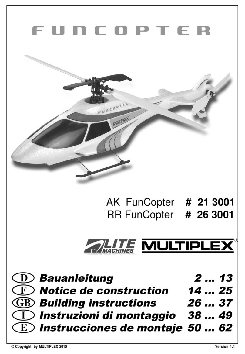
Lite Machines LMH-110 User manual

Warnings
WARNING! THE RADIO CONTROLLED MODEL HELICOPTER BUILT FROM THIS KIT IS
NOT A TOY, AND IS NOT MEANT FOR CHILDREN. IT IS A FLYING MACHINE
CAPABLE OF CAUSING PROPERTY DAMAGE AND SERIOUS BODILY HARM
TO THE OPERATOR AND SPECTATORS IF NOT BUILT AND OPERATED
CORRECTLY AND RESPONSIBLY. ROTATING COMPONENTS, ESPECIALLY
THE MAIN ROTOR BLADES, ARE AN EVER-PRESENT DANGER.
WARNING! Helicopters, by their nature, are not positively stable. Even if assembled and
adjustedproperly,helicopterswillnotholdaparticularflightpositionwithoutconstant
control inputs from the pilot, and will not automatically recover from an unwanted
flight attitude without pilot intervention.
WARNING! It is your exclusive responsibility to correctly and responsibly build, maintain and
operate this helicopter. Lite Machines has spent considerable time making this
product reliable and easy to build, but only the operator can ensure that it is safe.
Because the safe operation of this helicopter is beyond the control of the
manufacturer and distributor, the owner/operator assumes all risk of use.
WARNING! THIS PRODUCT CONTAINS CHEMICALS WHICH ARE KNOWN BY THE STATE
OF CALIFORNIA TO CAUSE CANCER, BIRTH DEFECTS AND/OR OTHER
REPRODUCTIVE HARM. Many common materials, such as metals, plastics, glues,
fuels, lubricants and coatings contain chemicals in varying amounts and
concentrations which will cause harm if introduced into the human body. Lite
Machines strives to produce safe and reliable products, and is interested in the
well-beingofeveryuserofitsproducts.Formoreinformationonchemicalscontained
in Lite Machines’ products, please contact Lite Machines Corporation. For further
information on toxic or dangerous chemicals, please refer to California’s health and
safety codes sections 25249.5-13.
Operator's Guide Warnings
LITE MACHINES

Acknowledgments
We thank all of those people who helped make Lite Machines Corporation possible.
WeespeciallythankMomandDad.Withouttheir helpandconstantencouragement
we could not have done this.
David and Paul Arlton
Lite Machines Corporation
Purdue Research Park
1291 Cumberland Avenue
West Lafayette, IN 47906
USA
Tel: (765) 463-0959
Fax: (765) 463-7004
www.litemachines.com
PATENT
NOTICE Most aspects of Lite Machines helicopters including, but not limited to, the main
rotor, main rotor blades, tail rotor, tail rotor blades, Arlton Subrotor™ stabilizer,
Arlton Gyro™ stabilizer, swashplate, fuselage structure and configuration, radio
installation configuration, landing gear and drive train are either patented (U.S.
5305968, 5597138, 5609312, 5628620, 5749540, 5879131, 5836545, 5906476,
6053146,6142419;Australia 681287,686883;Europe 0605656,95918276.7-2312,
95932305.6-2312, 96928019.7; France 0605656; Germany 69221307.4; U.K.
0605656), patent pending or patent applied-for in the United States and in other
countries. For information concerning patents and licensing, please contact Lite
Machines Corporation.
© Copyright Lite Machines Corporation, 2001. All rights reserved.
Revision VP8.3 1001
Operator's Guide Acknowledgments
LITE MACHINES

Table of Contents
Model Helicopter
Safety 1-1
Fuel Safety ...................1-1
Flight Safety...................1-2
Electric Power Safety ..............1-3
General Safety .................1-3
Terminology
and Controls 2-1
Helicopter Controls ...............2-2
Holding the Transmitter .............2-4
Electric Motors 3-1
The Corona Electric Helicopter .........3-1
Basic Theory of Electric Power .........3-1
Batteries.....................3-2
Electro-Magnetism and Electric Motors .....3-2
Brushed motors .................3-3
Adjustable Timing .............3-4
Brushless Motors ................3-5
Problems with Brushed Motors .........3-6
Three-Minute Motor Overhaul..........3-6
The Fusion 35 Speed Controller ........3-9
Arming the Fusion 35 ..............3-10
Optional RF Filter ................3-11
Cable Connections ...............3-11
Battery Elimination Circuitry (BEC) .......3-12
Charging Batteries ...............3-12
Battery Chargers ................3-13
Flying Weight ..................3-14
LITE MACHINES
Operator's Guide Table of Contents

Glow-Fuel Engines 4-1
General Operating Considerations .....4-1
Fuel Mixture and Compression .......4-1
The Importance of Clean Fuel .......4-3
Synthetic Oils ................4-3
Breaking-In a New Engine .........4-4
Engine Starting Summary..........4-4
Preferred Engine Starting Procedure ....4-5
Alternate Starting Method..........4-9
Adjusting Fuel Mixture and Compression..4-10
Inspecting SpiraLite Speed Glow Plugs...4-11
Electric Starter Effect on Glow Plug.....4-12
Main Rotor
Stability and Control 5-1
Rotor Blade Designations..........5-1
Blade Tracking ...............5-1
Dynamic Balancing .............5-3
Helicopter Stability .............5-3
Adjusting Main Rotor Blade Pitch......5-4
Stability and Climb Performance ......5-4
Learning to Fly 6-1
Training Gear ................6-2
Step 1: Learn the Left Stick .........6-3
Step 2: Practice Small Hops ........6-3
Step 3: Learn the Right Stick ........6-4
Main Rotor Controls.............6-5
Forward Flight and Translational Lift ....6-7
Circles....................6-8
Figure 8’s and Nose-In Hovering ......6-10
Descending from Altitude ..........6-11
Landing ...................6-11
Piezo Gyro Stabilizers ...........6-12
Adjusting the Arlton Gyro Stabilizer.....6-13
Tail Swing and Revo Mix ..........6-13
LITE MACHINES
Operator's Guide Table of Contents

Zen and the Art of
Helicopter Maintenance 7-1
General Maintenance ..............7-1
Engine Maintenance ..............7-1
Brushed Motor Maintenance ..........7-2
Radio Maintenance ...............7-2
Tail Rotor and Arlton Gyro Maintenance ....7-2
Main Rotor Maintenance ............7-3
Power Train Maintenance............7-3
Field Equipment Maintenance..........7-3
Making Repairs with CA and Glass Fiber ....7-4
Making Repairs with CA and Baking Soda ...7-5
Fixing a Bent Tail Boom.............7-5
Straightening a Bent Main Shaft ........7-5
How Helicopters Work 8-1
Introduction ...................8-1
Background and History.............8-2
Standard Helicopter Configuration .......8-2
Main Rotor Control ...............8-3
Main Rotor Stability ...............8-6
Retreating-Blade Stall ..............8-7
Anti-Torque Systems ..............8-8
Gyro Stabilizers .................8-9
Trouble-Shooting
Glow Engines 9-1
Trouble-Shooting
Brushed Motors 10-1
Operator's Guide Table of Contents
LITE MACHINES

Model Helicopter Safety
This section contains important safety information regarding proper handling and
operation of Lite Machines helicopters and accessories.
Fuel Safety
1. Use ONLY commercial fuel developed for model engine use. NEVER USE
GASOLINE, DIESEL, OR ANY OTHER FUEL! These fuels will ruin model
engines, and can explode and burn causing injury to YOU and OTHERS.
2. DO NOT OPERATE MODEL ENGINES INDOORS! Hot engine parts and
exhaust could ignite carpeting, drapery or furniture. Engine exhaust also
contains large amounts of unburned oil that will soil interior furnishings.
3. Never fuel or prime with the glow-plug battery connected to the engine. Sparks
from the electric connection could start a fuel fire.
4. Never fuel, prime, or operate your model while smoking.
5. Store fuel in a cool dry place protected from sunlight and from potential ignition
sources (anything burning, or anything that could start a fire if exposed to fuel
such as shorting or sparking battery terminals or the furnace in your home).
6. Remove excess fuel from your model with a cloth after refueling or priming. Raw
fuel can damage paint and is a potential fire source.
7. Do not store fuel in your model.
8. Fuel is poisonous and can cause death or blindness if swallowed. If swallowed,
induce vomiting and call for medical assistance immediately.
9. Fuelisaneyeirritant.Incaseofcontactwitheyes,flushthoroughlywithwater.
10. Raw fuel will damage certain types of plastic. Prescription plastic lenses and the
clear plastic commonly used on radio transmitter meters will be damaged if
exposed to raw fuel (such as droplets sprayed from the engine during starting).
Wipe off immediately using spray window cleaner.
IF FIRE SHOULD OCCUR:
1. MODEL FUEL BURNS WITH A NEARLY INVISIBLE FLAME, BE VERY
CAREFUL!
2. Useafireextinguisher,orsmotherfirewithaCLEAN,heavycloth.Iffirepersists,
GET AWAY! Better to lose the model than risk severe burns.
Operator's Guide Model Helicopter Safety
LITE MACHINES 1-1

Flight Safety
1. ALWAYS WEAR APPROPRIATE EYE PROTECTION WHEN OPERATING
YOURMODEL. Fueldroplets,looseparts,andairbornedebrisejectedfromyour
model could cause serious injury or blindness. Select comfortable, well-fitting
eyewearwithhigh-impactresistancesuchasshopglasses.Prescriptionglasses
made of glass are dangerous because they could shatter if struck sharply.
2. ALWAYSWEARAPPROPRIATEHEARINGPROTECTIONWHENSTARTING
AND ADJUSTING YOUR ENGINE. Many car, airplane and helicopter modelers
ignore the sound produced by the engines on their models. High volumes and
highfrequenciesproducedbymodelenginescandamagehearing.Thisdamage
can be cumulative. Ear-phone and ear-plug style hearing protectors (sold in
sporting goods stores in the gun section) are inexpensive and effective at
reducing the most damaging and annoying qualities of engine sound. Once your
model is started and flying, hearing protection is usually not necessary.
3. NEVERSTANDOR PLACEYOUR EYES ORFACE IN-LINE WITHROTATING
MAINROTORORTAILROTORBLADES.Loosepartsordebristhrownoutward
from rotating rotors could cause injury or blindness.
4. NEVER, EVER FLY NEAR OR OVER PEOPLE. Always keep your model at a
safe distance from yourself and spectators.
5. Use only those model engines designed specifically for your Lite Machines
helicopter. Use of more powerful engines (such as racing engines) is potentially
dangerous and voids all warranties.
6. Do not use fuel containing more than 35% nitromethane. The added power and
heat of high nitro fuels can damage both the engine and your model.
7. Never allow main rotor speed to exceed 2000 RPM (as by operating with blade
pitchsettoolow,orusing ahighpowered enginewithhigh nitrofuel).Rotor parts
couldseparate fromtherotorheadandcauseserious injuryorpropertydamage.
Very high speeds can also damage the engine.
8. Flyonlyatapprovedflyingfieldsorinopenareasawayfrompeopleandproperty.
Do not fly in residential areas.
9. Before turning on your radio, ensure that your radio frequency is not already in
use. Flying clubs have organized frequency sharing procedures.
10. Range check your radio prior to the first flight of each day. If your range check is
lower than normal, do not fly.
11. Priortothefirstflightof each day, check all mechanics for smooth, unobstructed
operation. Before the main rotors reach flying speed, gently move all flight
controlsandconfirmproperfunction.Donotflyifanythingisoutoftheordinary.
12. Check for hidden damage after crashing, and replace any damaged
components.
13. Beginners should have the main rotors tracked, and model adjusted for flight by
an experienced modeler.
Operator's Guide Model Helicopter Safety
1-2LITE MACHINES

Electric Power Safety
1. Electric power systems can be very dangerous. High electric currents can heat
wires, cause sparks and lead to fires and personal injury. DO NOT TO TOUCH
EXPOSED ELECTRIC COMPONENTS, AND NEVER FLY AT A SITE
LOCATED NEAR FLAMMABLE MATERIALS.
2. Electric motors are almost silent, and the main rotor and tail rotor blades of an
electric helicopter can start tuning unexpectedly causing serious injury. MAKE
SURE THE TRANSMITTER IS SWITCHED ON BEFORE CONNECTING THE
SPEED CONTROLLER AND BATTERY ON AN ELECTRIC HELICOPTER.
ALWAYS DISCONNECT THE BATTERY FROM THE SPEED CONTROLLER
WHEN CARRYING AN ELECTRIC HELICOPTER.
3. ALWAYS DISCONNECT THE MOTOR POWER CABLES WHEN ADJUSTING
THE RADIO SYSTEM ON A HELICOPTER SO THE MAIN ROTOR BLADES
CANNOT START TURNING. TO AVOID A SHORT CIRCUIT, BE CAREFUL
NOT TO TOUCH THE ENDS OF THE POWER CABLES TOGETHER.
4. Electric power systems, electronic components and batteries contain chemicals
such as lead and antimony which are known by the state of California to cause
cancer and birth defects.
General Safety
1. Periodically check tightness off all bolts, nuts, set screws and pins. Loose parts
couldbeejectedfromyourmodelcausinginjuryorcausingthemodeltocrash.
2. Replace broken or worn components with original parts only. To prevent
recurring problems it is important to locate and understand the cause of failure
(including pilot error).
3. Never modify any part of the main rotor, tail rotor system or drive train.
Modifications could lead to part failure.
4. Always replace the main and tail rotor blades in sets if damaged.
5. Donotstoreyour model indirectsunlight.Prolonged exposure toultravioletlight
can weaken some types of plastics.
6. When flying in very cold conditions be aware that metals and plastics (even
flexible ones) can become brittle and break or shatter.
7. Keep your model, radio and field equipment clean and in good repair. While
cleaning and maintaining your model you can often find and fix potential
problems (such as loose or damaged parts) before they occur.
8. Do not use solvents to clean or degrease rotor blades. Solvents can attack the
plastic and cause the blades to fail unexpectedly resulting in serious injury.
Operator's Guide Model Helicopter Safety
LITE MACHINES 1-3

Terminology and Controls
This section contains information on helicopter terminology and flight control
functions. Review the figures and become familiar with the names and functions of
themajor componentsand controls.Formore informationonhelicoptercontrolssee
the How Helicopters Work section of this Operator’s Guide.
Hint: Ifyouwantlastingrespectfromhelicopterflyers,don’tcallthemainrotorandtailrotor
blades “propellers”, and don’t call the right-left cyclic (pronounced sigh’-click) and
fore-aft cyclic controls “aileron and elevator”. This reveals your true identity as an
airplane person and diminishes your credibility among helicopter pilots. Also, don’t
call the swashplate, “that thing with bearings in it connected to the main rotor.”
O-Heli part names
Operator's Guide Terminology and Controls
LITE MACHINES 2-1
Figure 2-1.

Helicopter Controls
Toflyamodelhelicopter you must first understandthefunctionofeachflight control.
Fig. 2-2through Fig. 2-5illustrate the flight motions produced with the right cyclic
(pronounced “sigh-click”) stick on the transmitter. The right stick tips the rotating
main rotor in the direction of the stick motion and controls the direction of horizontal
flight.
O-Stick Roll
As shown in Fig. 2-2, moving the stick left and right tips the main rotor left and right
(like aileron control on an airplane).
O-Stick pitch
As shown in Fig.2-3, moving the stick forward and backward (up and down) tips the
main rotor forward and backward (like the elevator control on an airplane). When
learning to use the right stick, it is helpful to think of it linked to an imaginary control
stick mounted vertically on top of the main rotor. As you push the transmitter stick
forward, you also push the imaginary control stick forward and tip the main rotor
forward. Imagine the same for backward, left and right.
Operator's Guide Terminology and Controls
2-2LITE MACHINES
Figure 2-2.
Figure 2-3.

O-Stick yaw
Fig.2-4andFig.2-5showtheeffectofmovingtheleftstickonthetransmitter.Theleft
stick controls the tail rotor and throttle.
As shown in Fig.2-4, movingtheleft sticktothe leftandrightchangesthepitchofthe
tailrotor bladescausing thehelicoptertorotatetotheleftorright(likesteeringacar).
Note that the left stick rotates the NOSE to the left and right. Always concentrate on
theNOSE whenusingtheleftsticktoturn.Youwillbecomeconfusedifyouwatchthe
tail.
O-Stick throttle
Moving the left stick up and down increases or decreases engine speed causing the
helicopter to climb or descend as shown in Fig.2-5. On collective-pitch helicopters,
the left stick also controls the pitch angle of the main rotor blades.
Operator's Guide Terminology and Controls
LITE MACHINES 2-3
Figure 2-4.
Figure 2-5.

Holding the Transmitter
Model airplane fliers commonly hold their transmitter so only their thumbs touch the
transmitter sticks. When flying with thumbs, it is easy to unintentionally mix controls
by moving the right stick up and to the right, and the left stick up and to the left.
O-Hands on transmitter
To control your helicopter more accurately, hold the control sticks with both your
thumbsandindexfingersasshowninFig.2-6.Italsohelpstowearatransmitterneck
strap to support the transmitter and take the weight off your hands.
Note: Even though he drawings show the transmitter antenna retracted, always extend
your transmitter antenna before flying for the best possible radio range.
Operator's Guide Terminology and Controls
2-4LITE MACHINES
Figure 2-6.

Electric Motors
Thissectiondescribesbasic principles ofelectricpoweredflight and theoperationof
Electro-Fusion brushed motors. If you have a gas-powered helicopter you can skip
this section.
The Corona Electric Helicopter
Before it made its first flight, the Corona electric helicopter was optimized by a
computer program to fly at maximum efficiency withElectro-Fusion brushed motors.
The rotor systems and motors were matched to achieve the best lift-to-drag ratio of
the rotor blades for a particular weight, speed and motor efficiency.
After computing the best design parameters, prototype parts were developed and
testedon an instrumented whirl stand to generate test data (such as lift, drag and air
velocity measurements) at dozens of points around the main rotor and tail rotor. The
measurements were fed back into the computer program to further optimize the
design.
There are many interrelated design variables in the Corona helicopter, so it is
practicallyimpossibletooptimizethedesignbytrialanderror.Abasicunderstanding
ofelectricpowered flight, however,willgreatly aid youinsuccessfullyoperating your
Corona helicopter.
Basic Theory of Electric Power
Electricity is commonly measured in units of volts (abbreviated “V”), amperes (“A”),
ohms (“Ω”)and watts (“W”). By analogy, electric current flowing through awireislike
water flowing through a pipe.
Electric potential is measured in volts (positive and negative) and can be thought of
aspressureinawater pipe.Ifthepressureat oneendofthepipe ishigherthanatthe
other end, the pressure difference will push water through the pipe. If there is no
pressure difference, then no water will flow.
In a similar way, voltage difference in a wire pushes electrons through the wire from
the negative end of the wire to the positive end. If there is no voltage difference, no
electrons will flow. A seven-cell NiCad battery pack produces about 8.4 volts of
electric potential.
Electric current is measured in amperes (“amps” for short), and is related to the
amount of electrons (actually electron waves) flowing through a wire. A large
diameter wire can conduct more electrons than a small wire in the same way a large
Operator's Guide Electric Motors
LITE MACHINES 3-1

diameterpipecan carrymorewaterthan asmallpipe. TheCoronaelectrichelicopter
normally flies on about 11 to 19 amps of electric current.
Electric resistance is measured in ohms and represented by the Greek letter omega
(Ω).Resistance slowsdownorinhibitsthe flowofelectronsina wirelikeaplugslows
down the flow of water in a pipe. When electric resistance inhibits the flow of
electrons, the energy of the electrons is converted to heat (this is how an electric
stoveworks).TheFusion35motorspeedcontrollerhasaninternalresistanceofonly
about 0.005 ohms (this is really low), and, as a result, stays cool in operation.
Power is measured in watts which is simply amps multiplied by volts. A Corona
electrichelicopterdrawing12ampsfroman8.4voltbatteryconsumes100.8wattsof
power (12A x 8.4V = 100.8 W).
Batteries
Batteries store electric energy in various ways, but each type of battery has a
characteristic voltage and a maximum current storage capacity. The
Nickel-Cadmium (NiCad) battery cells used in yourCorona helicopter each produce
a maximum of about 1.2 volts.
Batteriescanbeconnected end-to-end in“series”toincreasevoltage or side-to-side
in “parallel” to increase current capacity. Six-cells connected in series to form a
standardsix-cellpackproduceabout7.2volts(1.2Vx6cells=7.2volts).Seven-cells
connected in series produce about 8.4 volts (1.2V x 7 cells = 8.4 volts).
Battery capacity is measured in milliampere hours which is abbreviated “milliamp-
hours”or “mAh”.Amilliamprepresents1/1000th ofanampofcurrent(0.001A),anda
milliamp-hour represents 1/1000th of an amp of current flowing for one hour. A 2400
mAhbatterycanproduce2400 milliamps of currentforonehour.This is the sameas
2.4 amps for one hour, 1.2 amps for two hours or 0.6 amps for four hours.
All batteries and motors have internal resistance that causes them to heat up in
operation. The more current flowing through a battery or motor, the more heat
produced. Since the idea behind electric power is to convert the electric energy
stored in a battery to mechanical energy, any heat generated is a measure of
inefficiency and waste. Generally, expensive batteries have lower internal
resistance than cheap batteries, and provide longer flight times with more available
power.
Electro-Magnetism and Electric Motors
When electric current flows through a coil of copper wire, the current generates a
magnetic field (also called an “electro-magnetic” field). The strength of the magnetic
fielddependson thevoltage,current andnumberofwinds inthecoil. Thestrengthof
thefieldcanbegreatlyincreasedbywindingthecoilsaroundachunkofironmetal.
Operator's Guide Electric Motors
3-2LITE MACHINES

Likeallmagnets,electro-magnetshave anorthpoleandsouth pole.Northandsouth
poles attract each other. When two magnets are placed next to each other, the
magnets tend to rotate so the north pole of one magnet aligns with the south pole of
the other.
Electric energy stored in a battery can be converted to mechanical energy by an
electric motor which uses electro-magnetic fields to rotate an output shaft. Model
motors come in two basic varieties, “brushed” and “brushless”, which differ in terms
of how electric current gets to the copper coils or “windings” inside the motor.
Brushed motors
O-Brushed motor operation
In a “brushed” motor, electric current flows through carbon brushes that slide on a
copper commutator ring attached to the motor output shaft as shown in Fig.3-1. The
commutatorringgenerallyhasthreesegmentsattachedtothreecoilsofcopper wire
each wrappedaroundanironcore. Themotorshaft, commutator,coilsand ironcore
are collectively referred to as the motor “armature”.
As the armature rotates, the brushes conduct current to each segment on the
commutator and through one coil after another. The energized coils produce
magnetic fields that pull the coils toward permanent magnets mounted on the inside
of the motor body (also called the motor “can”). As each coil passes a permanent
magnet, the brush associated with that coil slides onto the next commutator
segment. This de-energizes the coil and energizes the next one in sequence.
Operator's Guide Electric Motors
LITE MACHINES 3-3
Figure 3-1.

The speed of rotation of a brushed motor is determined by the load on the motor, the
amountof current passing through the coils, the number of turns or winds in the coils
andtheoperatingvoltage.Motorsrunningathighvoltagearegenerallymoreefficient
because less current is needed to generate power, so less energy is lost as heat.
Also, motors with fewer turns have more power and run faster, but are generally less
efficient than motors with more turns.
Brushed motors are easy to manufacture, but are inefficient to operate. Only about
75% of the electric enery entering the motor is converted to mechanical energy. The
rest is converted to heat by the electric resistance of the brushes and by conflicting
magnetic fields inside the motor.
O-Brushed eff graph
As shown in Fig. 3-2, which is a graph of motor efficiency at various motor speeds,
brushed motors are most efficient within a very small speed range. Outside of this
range efficiency drops quickly, and most of the electric energy entering the motor is
convertedtoheat.Whenamotoroperatesoutsideitsefficientspeedrangethemotor
body becomes very hot (sometimes too hot to touch), and the motor coils can burn
out.
Adjustable Timing
Motor coils cannot energize instantly when current is applied. This poses a problem
for brushed motors running at high speed because the coils energize at the wrong
time and generate conflicting magnetic fields that push on the permanent magnets
when they should be pulling (and vice versa). Some brushed motors, such as the
Electro-Fusion motor on your Corona helicopter, have adjustable timing to address
Operator's Guide Electric Motors
3-4LITE MACHINES
Figure 3-2.

this problem. To adjust the point at which the brushes touch the commutator
segments, the motor end-bell can be rotated relative to the motor body.
“Advanced” timing gives the coils more time to develop a strong magnetic field so
they can pull on the permanent magnets longer and with less magnetic conflict.
Timing of the Electro-Fusion motor on the Corona helicopter is usually set between
15 and 20 degrees for best results.
Brushless Motors
Brushless motors require no brushes. The copper coils are usually located on the
outersurfaceofthemotorcase(insteadofonthespinningarmature)wheretheycan
be connected directly to a power supply. The permanent magnets are mounted on
and rotate with the output shaft. A small, computerized speed controller turns the
coils on and off at the appropriate time to operate the motor at a particular speed.
Brushless motors are more difficult and expensive to manufacture than brushed
motors,butaremoreefficientandpowerful.Withnobrushestoburnout,thecoilscan
carry very high currents. Since the computer operated speed-controller can be
programmed to turn the coils on and off at just the right time, the power loss
associated with conflicting magnetic fields is very low.
O-Brushless eff graph
Efficiencies of good brushless motors approach 90% (that is, 90% of the battery
power going into a brushless motor ends up rotating the output shaft). As shown in
Fig. 3-3, brushless motors also can operate efficiently over a wide speed range. At
such high efficiencies, brushless motors tend to run cooler than brushed motors
because less electric power is wasted as heat.
Operator's Guide Electric Motors
LITE MACHINES 3-5
Figure 3-3.

Problems with Brushed Motors
Electro-Fusion motors are modified versions of standard 540-size brushed motors.
The original 540-size motors made in the 1980’s produced about 50 watts of power,
but Electro-Fusion motors can produce as much as 150 watts with the same size
brushes.Since thebrushes and commutatoronmodern motors handlemorepower,
they wear down more quickly. Brush and commutator wear is the primary source of
power loss in brushed motors.
Motorbrushesaretypicallymade ofcarbon,copperandsilver, andvaryinhardness.
Whenabrushedmotor turns at highspeed,theendsof the brushes andcommutator
slide against each other and wear down. If the brushes have hard spots, or wear
unevenly, the commutator can also wear unevenly. As the gap between the
commutator and brushes becomes more uneven, small sparks jump between the
brushes and commutator and accelerate the wear of both. This uneven gap also
increases electric resistance.
Asresistancegoesup,sodoestheheatgeneratedbythecurrentflowingthroughthe
brushes and commutator. This heat eventually burns the brushes and turns them a
deep blue color. When this happens, brush manufacturers say, certain lubricating
components are burned out further accelerating brush wear.
Oncea brush has worn down to the point where it no longer touches the commutator
it must be replaced. If the commutator wears unevenly, it must be resurfaced on a
commutator lathe or the entire armature must be replaced.
Commutator surface finish is possibly the most overlooked problem with brushed
motors because relatively few modelers take apart and inspect their motors. As high
electriccurrentspassbetweenthemotorbrushesandcommutator,thesurfaceofthe
commutator heats up and oxidizes turning a deep black color. This black finish
increasestheelectricresistanceofthecommutator/brushconnectionandconsumes
battery power. Removing the black surface finish can restore electric conductivity
and proper commutator function.
Three-Minute Motor Overhaul
Forthebestlong-termperformanceofyourElectro-Fusionmotor,service yourmotor
every six to ten flights using this simple three-minute procedure.
1. Disconnect the flight battery from the speed controller, and the power cables
from the motor, but leave the motor in your Corona helicopter.
2. Remove the motor pinion gear.
3. Pullthebrushesoutpasttheendofthebrushspringssothebrushesdonotcatch
on the commutator washer.
Operator's Guide Electric Motors
3-6LITE MACHINES

O-Remove end-bell
4. Loosen (but do not remove) the end-bell screws. Rotate the end-bell assembly,
and pull it off the motor as shown in Fig. 3-5.
5. Remove the armature from the motor can.
O-Worn brush and comm
6. Inspect the brushes. If the brushes are less than 3/16” (5 mm) long, or if the
brushes are burnt and discolored, replace with new ones.
Warning! DO NOT USE REPLACEMENT BRUSHES WITH A SERRATED OR WAVY
RUNNING SURFACE. The serrated surface will cut into the commutator and
damage it.
Operator's Guide Electric Motors
LITE MACHINES 3-7
Figure 3-4.
Figure 3-5.

7. If the commutator is worn unevenly as shown in Fig. 3-4, replace the entire
armature with a new one. This will significantly increase motor power.
O-Comm clean #1
8. If the commutator surface is smooth but dark and discolored, clean it with a
LiteBritecommutatorcleaning paduntilit isashiny coppercolor(six totentwists
by hand) as shown in Fig. 3-6.
O-Comm clean #2
9. Run a hobby knife in the slots between the commutator segments to remove
loose particles as shown in Fig. 3-7.
Operator's Guide Electric Motors
3-8LITE MACHINES
Figure 3-6.
Figure 3-7.
Table of contents
Other Lite Machines Toy manuals
Popular Toy manuals by other brands

Hobbico
Hobbico Sky Vapor HCAA0315 Assembly instructions

IKC
IKC Fence low PW manual

Beyblade
Beyblade Lightning L-Drago instructions

Hornby
Hornby CLASS 2800 Operating and maintenance instructions

HYPE
HYPE G-103 Twin III Acro instruction manual

Black Horse Model
Black Horse Model TAYLORCRAFT instruction manual