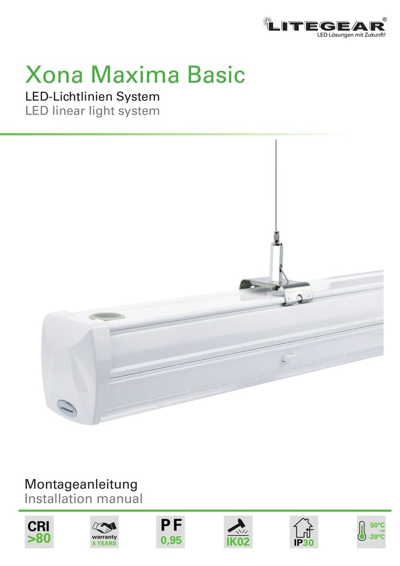
LiteGear Xona Maxima Basic User manual

Xona Maxima Anleitung / manual 1
CRI
>80
IP30
5 YEARS
Guarantee PF
0,95
IK02
-20°C
BIS
50°C
LED Lichtlinien System
LED linear light system
Montageanleitung / Installation manual
Xona Maxima Basic

2 Xona Maxima Anleitung / manual
Allgemeine Hinweise
General information
Allgemeine Sicherheitshinweise / General safety instructions:
DE
!
Um die Gefahr von Personen- oder Sachschäden durch Feuer, Stromschlag, herabfallendeTeile, Schnitte /
Abschürfungen und andere Gefahren zu vermeiden, beachten Sie bitte die folgenden Hinweise, bevor Sie
die Leuchte montieren.
• Lesen Sie die Anleitung vor der Montage/Inbetriebnahme und übergeben Sie diese nach der Montage dem
Kunden zur Aufbewahrung.
• Keine beschädigten Produkte montieren.
• Bei einer unsachgemäßen Montage oder Änderungen im Nachhinein wird keine Haftung übernommen.
• Zum Schutz der Leuchte und der Oberfläche vor Verschmutzungen und Fingerabdrücke empfehlen wir das
Tragen von Schutzhandschuhen.
• Vermeiden Sie den direkten Blick in die eingeschaltete Lichtquelle.
• Halten Sie brennbare Materialien von der Leuchte/Linse fern.
• Kleinteile und Verpackungsmaterial aus der Reichweite von Kindern fernhalten.
Achtung:
• Achten Sie auf die Landesüblichen Unfallverhütungsvorschriften.
• Die Montage und Instandhaltung darf nur von qualifiziertem Personal durchgeführt werden.
• Überprüfen Sie die Spannungsfreiheit des Systems vor der Montage.
To avoid the risk of personal injury or property damage from fire, electric shock, falling parts, cuts / abrasions
and other hazards, please read the following notes before mounting this device.
• Read the instructions before mounting /installation and hand it over to the customer for storage after
installation.
• Do not mount damaged products
• No liability is accepted for improper installation or changes afterwards
• We recommend wearing protective gloves to protect the luminaire and the surface from dirt and finger-
prints.
• Avoid looking directly into the switched on light source.
• Keep small parts and packaging material out of the reach of children.
EN
Caution
• Pay attention to the local safety and accident prevention guidelines.
• Installation and maintenance may only be carried out by qualified personnel.
• Make sure that the system is switch off before installation.
!
Produktübersicht/ product preview:
LG31711
Universal-
montageclip
universal clip
LED-Modul mit Batterie, Notstrom 8,12-adrig
LED module with battery emergency light 8,12
wire
LED-Modul (optional dimmbar) 5(8)-adrig
LED module (dimming option) 5(8) wire Leuchtenträger mit 3 phasiger Stromschiene
599-1499mm
cover with rail out 3-phase for tracklight 599-
1499mm
LG31712
Adapter für
Rasterfelddecken
clip for grid
ceiling
LG31709
Adapter für
Gewindestange
Steel rod suspen-
sion
LG31705
Adapter mit
Stahlseil
wire suspension
Adapter für
Kette
chain
LG31740
LG31741
Endkappe
endcap
LG31733
LG31734
Einspeisung
feed in
LG31746
Endbox
endbox
OFF
Aus

Xona Maxima Anleitung / manual 3
Installation und Montage
Installation
1Tragschiene (1499/2999mm) trunking rail (1499/2999mm)
2Kabeleinführung cable inlet
3LED-Modul LED module
4LED-Treiber LED driver
5Verriegelung lockers
6Endkappe endcap
7Kontakt-Terminal male male connector
8Kontakt-Terminal female female connector
9optionale Aufhängung optional suspensions
6
9
9
2
1
3
5
6
4
7
8
Technischer Aufbau (einzelne Leuchte) / technical structure(single luminaire):
X-Verbinder
X-node
L-Verbinder
L-node
T-Verbinder
T-node
Sensor-Modul mit Verriegelung und phasenüber-
griff 599-1499mm
sensor module 599-1499mm
Blindabdeckung 599-1499mm(Stahl oder
Kunststoff)
blankcover 599-1499mm(steel or PC)
Leuchtenträger für Flucht-und Rettungs-
leuchten mit Phasenabgriff
steel blankcover for exit/emergency signs
Technischer Aufbau (Lichtlinie) / technical structure (line light):
1Tragschiene (1499/2999mm) trunking rail (1499/2999mm)
2Verbindungsplatte connecting plate
3Kabeleinführung cable inlet
4LED-Modul LED module
5LED-Treiber LED driver
6Verriegelung lockers
7Kontakt-Terminal male male connector
8Kontakt-Terminal female female connector
9optionale Aufhängung optional suspensions
2
1
3
4
5
7
8
9
6

4 Xona Maxima Anleitung / manual
Installation und Montage
Installation
PE Erdung / Ground
EL1 Notversorgung 1 / Emergency 1 Supply Live
EN1 Notstrom N1 / Emergency 1 supply Neutral
EL2 Notstrom L2 / Emergency 2 supply Live
EN2 Notstrom N2 / Emergency 2 supply Neutral
L1/L2/L3 stromführende Phase, entsprechender Neutralleiter ist N1 /
live wire, corresponding neutral wire is N1
L4/L5/L6 alternative stromführende Phasen, entsprechender Neutralleiter
N2 / another group of live wires, corresponding neutral wire N2
DIM+ 1-10V+
DIM- 1-10V-
DA/L DALI+ / Push Dim L
DA/N DALI- / Push Dim N
CHR Ladeeingang für interne Batterie, Hauptversorgungserkennung /
Charge input for internal battery, main supply detection
Funktionsbeschreibung
Function Description
Kabelbezeichnung
Description of the wires
Mode
3 phase DALI 1-10V Batt EMG1 EMG2 1 2 3 4 5 6 7 8 9 10 11 12
5-adrigeTragschiene:
5-core trunking rail
1•L1 NL2 PE L3
8-adrigeTragschiene:
8-core trunking rail
2• • • CHR L1 NL2 PE L3 DIM+ DIM-
3• • • CHR L1 NL2 PE L3 DA/L DA/N
4• • • CHR L1 NL2 PE L3 EL1 EN1
12-adrigeTragschiene:
12-core trunking rail
5• • • • • CHR L1 EL1 NEN1 L2 EN2 PE EL2 L3 DIM+ DIM-
6• • • • • CHR L1 EL1 NEN1 L2 EN2 PE EL2 L3 DA/L DA/N
7x2 • • CHR L1 L4 N1 N2 L2 L5 PE L6 L3 DIM+ DIM-
8x2 • • CHR L1 L4 N1 N2 L2 L5 PE L6 L3 DA/L DA/N
!
Bitte beachten Sie, dass nur die fünf Hauptkabel L1,L2,L3,N und PE in 2,5mm² (16A)
Querschnitt ausgeführt sind! Alle anderen Kabel haben einen Querschnitt von 1,5mm²
Note Only L1,L2,L3,N1 and PE wires are 2,5mm² with 16A, the rest are 1,5mm² with 10A:

Xona Maxima Anleitung / manual 5
Installation und Montage
Installation
L1 NL2 PE L3
12-adrig / 12 cores EN2
L5
EL1
L4 EN1
N2
L2
EL2
L6
PE
L3
DIM-
DA/N
L1
L2
CHR
N
N1
PE
DIM+
DA/L
CH
L1
N
L2 PE
L3
DIM+ / DA/L / EL1
DIM- / DA/N / EL1
5-adrig / 5 cores
8-adrig / 8 cores

6 Xona Maxima Anleitung / manual
Installation und Montage
Installation
Montage (eine Schiene) / mounting (one trunking rail ):
i N
i P
Montieren Sie ggf. den Haken
an die Decke / Fix mounting
hook into ceiling. in case it is
needed
Entfernen Sie das Gummi der
Kabeleinführung / remove the
rubber of cable inlet.
Schieben Sie den L1-3 Kontaktstecker
vomLed-ModulindieentsprechendePo-
sition: L1,L2,L3 um die Phase zu wecheln
Slide the male connector of the LED into
the corresponding position: L1,L2,L3 to
change the phase (power supply)
Stellen Sie sicher, dass male, femal
Kontakt-Terminal in der richtigen
Position sind, dann Befestigen Sie
das LED-Modul an der Stromschiene
make sure male & female connectors
are in the right position then fix the lu-
minare to trunking rail.
Positionieren Sie die Endkappe, um
die Leuchte von beide Seiten zu schlie-
ßen / Position the end cap to close the
luminaire from both sides
Führen Sie das Kabel mittels einer
Kabeleinführung ein / pass the ca-
ble during the cable intel.
Schließen Sie das Kabel im Stecker
mit der Schiene an / connect the
cabel via connector with the trun-
king rail.
Hängen Sie das Seil (Kette)
in dem Haken ein / Hang the
rope on the hook.
Drücken Sie den Ring auf
dem Montageclip um die
Länge des Seil zu justieren /
press the button on the clip
to adjust the length.
Drücken Sie den Clip auf
die Schiene / press the clip
on the trunking rail.
Zur Montage von mehreren Schienen zur Lichtlinie, wiederholen Sie die Schritte 1 bis 7 für jede Schiene, dann
verbinden Sie die Schienen wie unten beschrieben / to mounting many trunking rail as a line light repeat the step
from 1 to 7 for every trunking Rail, the connect it as shown below .
1 2
5
8 9 10
67
3 4
Montage (mehrere Schiene) / mounting (many trunking rail):
Xona Maxima Anleitung / manual 7
Installation und Montage
Installation
Montage (optionales Modul) / mounting (optional module ):
Das erste LED-Modul montieren
mounting the first LED-Module.
Das zweite LED-Modul montieren
mounting the first LED-Module.
Sensor-Modul montieren
mounting the Sensor-Module.
3000mm max. 100-800mm max.
Leuchtenträger mit Stromschienen montieren
mounting cover with rail out for tracklight.
Blindabdeckung montieren
mounting blankcover .
Bitte beachten Sie: Der erste Aufhängepunkt am Anfang bzw. Ende einer Lichtlinie darf ma-
ximal 100-800mm Abstand zum Anfang/Ende der Linie haben. Dies trifft ebenfalls auf die
Eckverbindungen zu / the first suspension point at the beginning or at the end of a light
line may have a maximal of 100-800mm distance to corner joint.
!
Drücken
press
drücken
push

8 Xona Maxima Anleitung / manual
2011/65/EU
Litegear GmbH
An Fürthenrode 45
52511 Geilenkirchen
Deutschland / Germany
Tel.: 0049 (0) 2451 / 48453-0
vertrieb@litegear.de
www.litegear.de
WEEE Reg. Nr.: DE 61698887
Stand: 01/21
Max. Anzahl der Leuchten an einer Phase / Max. Number of lights on one phase:
Installation und Montage
Installation
35W 35W DALI 50W 70W
Leitungsschutzschalter /
Circuit breaker
B16A 13 Unit 21 Unit 8 Unit 5 Unit
Leitungsschutzschalter /
Circuit breaker
C10A 12 Unit 22 Unit 8 Unit 5 Unit
Leitungsschutzschalter /
Circuit breaker
C16A 19 Unit 36 Unit 13 Unit 9 Unit
Einschaltstrom /
inrush current 25A 29A 30A 32A
Oberschwingungsgehalt /
harmonic distortion <20% <20% <20% <20%
Einschaltstromdauer /
inrush Charge time
TH50 220 µs 180 µs 400 µs 400 µs
Table of contents
Other LiteGear Light Fixture manuals

LiteGear
LiteGear Cetara Vario MKII Square 6262 36-827/865-3800LM... User manual

LiteGear
LiteGear LITEMAT 1 User manual

LiteGear
LiteGear Newtura User manual

LiteGear
LiteGear Cetara Office 6262 BAP 36-830-4320LM User manual

LiteGear
LiteGear Alvera MKII User manual

LiteGear
LiteGear Xona Maxima Basic Series User manual

LiteGear
LiteGear Modulux 60-14/20-830-2900lm-BK User manual
Popular Light Fixture manuals by other brands

RSA Lighting
RSA Lighting Combolight LV Series LV840MHSQ Specifications

Liton
Liton DL340 Series installation instructions

Underwater Kinetics
Underwater Kinetics UK4AA eLED Zoom-T user manual

JONATHAN Y
JONATHAN Y JYL6005A manual

L&S
L&S STAR LIGHT quick start guide

Triarch
Triarch Indoor Lighting 29465 Assembly instructions