Lites Lites F200 c5 Application guide

Lites
Lites F200 c5
Colour RGBWA
Owners ‘s & Service manual
Read t is manual totally and carefully follow all t e instructions contained. File t is manual for future
use. It is essential to read all t e information contained to ensure installation, service and full operation
of t e LitesF200.
All operations must be accomplis ed, andled and carried out by qualified personnel only. Not complying
wit given notice will void warranty and will free manufufacturer from any liability/responsability
www.litessrl.com

Pagina 2 di 8
Unpacking
Unpack the carton and gently remove Lites F200 from the box. nsure Lites F200 received is integer from origin in all
its components.
In the event the Lites F200 shows any damage, do not use it and contact immediately your transporter as well as your
seller.
Items in the carton consist of:
−
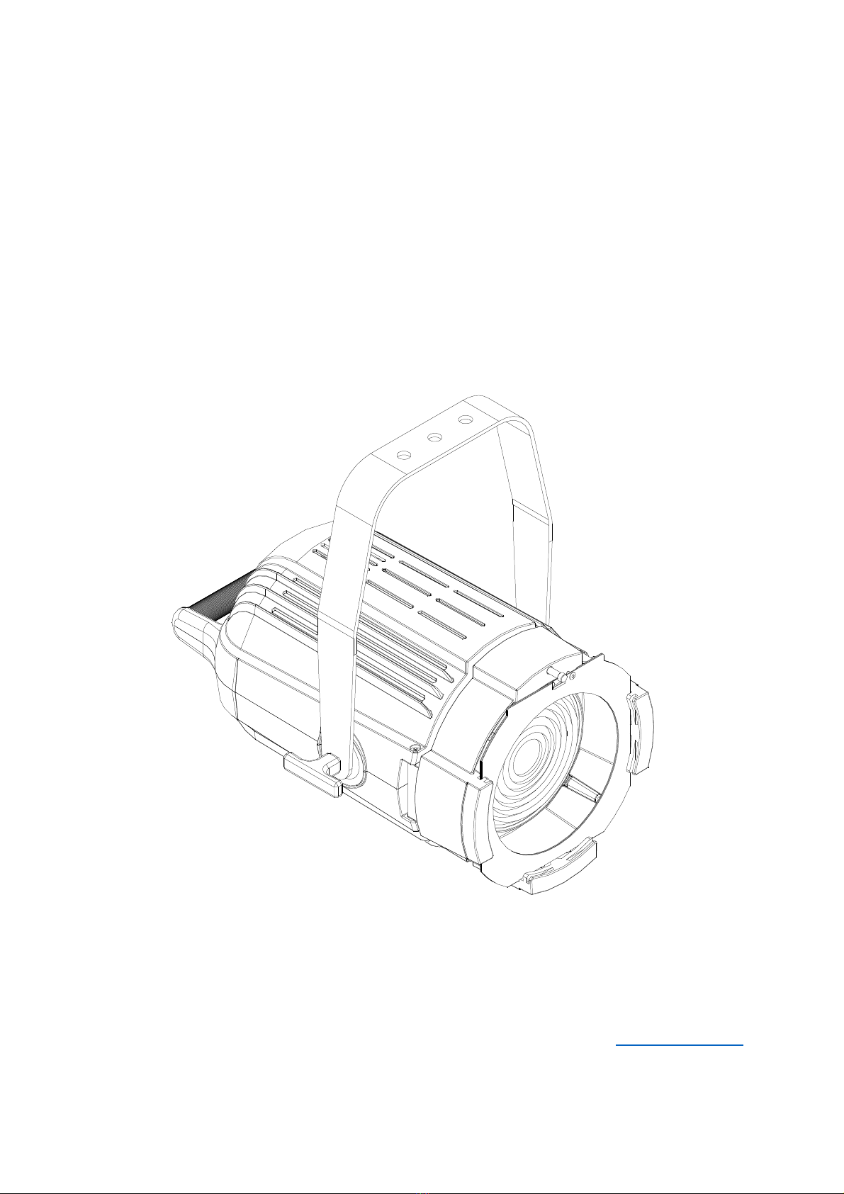
Lites F200 C5 luminaire
−
Colour frame
−
Blue Neutrik PowerCon connector
−
This owner's and service manual
Safety information for the use of the Lites F200 as well as its periodical maintenance”
‒
Lites F200 is for professional use only and N V R for domestic use therefore refrain from this latter utilisation.
‒
Users must scrupulously comply with information that follows, any other use in contrast will void warranty and
will free the manufacturer of any sort of responsibility and liability.
‒
Never use Lites F200 on any flammable surfaces.
‒
Minimum distance from any flammable source is of 0.25m.
‒
Minimum throw distance from illuminated surface: 0.5m.
‒
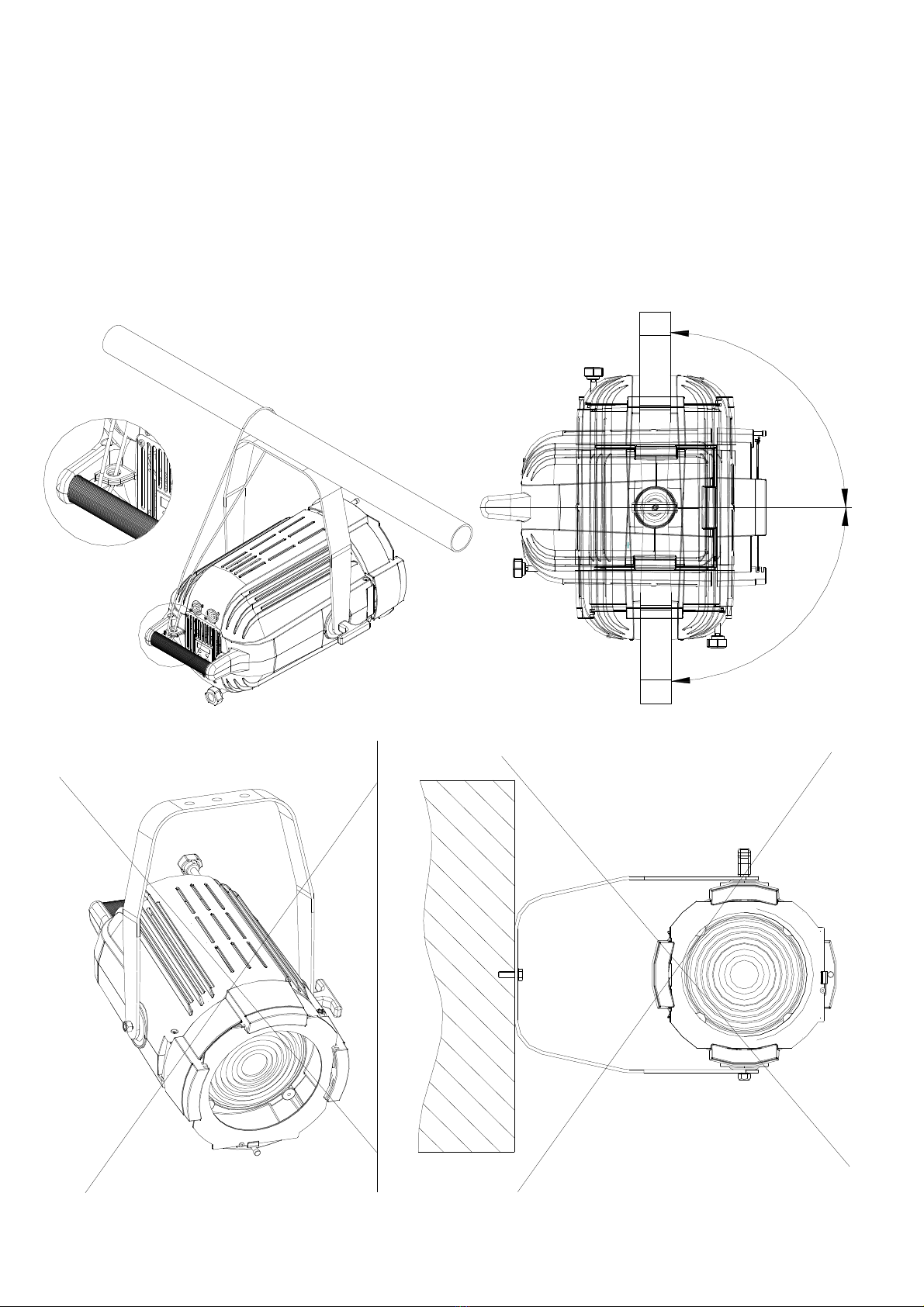
Installation of the unit(s) must be secured with adequate clamps, safety cords, nuts and bolts to bear the
weight of the whole unit(s)
‒
Always Power Lites F200 to safety circuit breakers. Lites F200 must NOTand CAN NOT be operated via Phase
Control Dimmer.
‒
Install Lites F200 in ventilated ambient which temperature must not trespass 35°C
‒
Some outer parts of the LitesF200 can reach temperatures of up to 60C° when in operation.
‒
Lites F200 must be fitted with protection shields (Lenses)
‒
On no account, directly or indirectly, L D must be touched
‒
Always disconnet power, (always double check that power is off) before any Service/Operation of the unit.
‒
Lites F200 is rated Class I.
‒
arth connection is MANDATORY!
An essential and periodically throughout cleaning of the Lites F200 is recommended. This practice avoids that layers of
dust and other impurities jeopardise and reduce the correct operation of the unit. Lenses must be cleaned to remove
layers of dust that may impede and or reduce the passage of the light through the lenses. The correct and periodically
maintenance keeps also fans and vents clean to keep the LitesF200 in its best performance conditions. Never touch the
Yellow core of the L D both directly or indirectly nor use solvents that can damage the L D irremediably. Protection
shields if battered, must be replaced with new ones (Lenses)
CE APPROVALS
The Lites F200 products to which this manual refers to, complies with uropean directive pursuant to:
2014/35/ U safety of electrical equipment supplied at low voltage (LVD)
2014/30/ U lectromagnetic compatibility ( MC)
2011/65/ U Restriction of the use of certain hazardous substances (RoHS)
WARRANTY
A 12-month warranty is granted on the LitesF200 from its purchase’s date. Warranty covers fabrication defects only,
unit will not be replaced but will be 100% fixed. Warranty is immediately voided if the Lites F200 has not been
handled by qualified personnel. Any improper and unauthorised use, such modification(s) or misapplication of the unit
will also void the warranty of the product(s). Silver colour label showing technical data and serial number, if removed
or if data are impaired to render details illegible, will immediately void the warranty.

Pagina 3 di 8
Technical specifications
Power Supply: 100/240V~ 50/60Hz (autosetting)
Maximum power consumption 200W
Stand-by power consumption 5W
Led RGBWA (Red ,green, blue ,white 6500°k, ambra)
Fresnel Lens: Ø 150mm
Colour frame dimensions: 195x185 mm (the use of standard 185x185mm colour frame is totally acccettable)
Aluminium die-caste body to maximize heat dissipation
Operating temperature range: -15°C + 35° C
Maxium temperature on the Lites F200 +60°C
Weight of the unit: Kg 6,9
Worm-gear beam adjustment on standard Lites200F
Rear handle for good grip of unit ; side-lock on mounting yoke to adjust and set unit to position.
Beam angle: 20°-60°
Working position: +90°/-90° on vertical axe
Protection rating: IP 20
DMX 512 , RDM, Protocols (wireless on request)
Neutrik powercon IN & OUT connectors
Neutrik XRL5 IN & OUT signal connectors
4-digit display
Manual operation via 4-digit display
Idle fan mode for totally silent use of the unit.
Adjustable L D frequency
Selection of two L D dimming curves
Comply with
Dimensions: see figure

Pagina 4 di 8
Lites200F installation
Lites F200 is delivered with a robust yoke which hosts 3 x 12 mm mounting holes.
The use of an adequate G-clamp to sustain at least twice the weight of the Lites F200 (Lites200F weighs 6,9 kg)
and/or M10 screw is mandatory. The use of safety chain(s) to sustain twice the weight of the Lites F200 is also
mandatory, the safety chain adds more protections to users and third-parties. ye-lid for the safety chain is provided
on the Lites F200. (see Fig)
The Lites F200 yoke revolves on 360° on the projector’s axis. Lites F200 can be installed +-90° on the vertical axis.
(see Fig.). Best Lites F200 ’s perfomrances are achiieved if unit is installed as shown in the illustrations that follows.
(never install Lites F200 upsidedown, illustrations that folllows show installation positions that must be avoided) .
Incorrect installation(s) can, immediately or in short/long terms, jeopardise the correct operaton of the Lites F200.
Incorrect installations may voide the warranty of the unit.
90°
90°
AVOID INCORRECT INSTALLATIONS AS ILLUSTRATED

Pagina 5 di 8
Installations of t e accessories
Lites F200 is delvered with a standard
195x185mm colour frame (standard colour
frame 185x185 can als be used). The L D
source used on LitesF200 allows the use of
colour filters that cannot be used with high
wattage tungstene lamps which would impair
colour filters. Optional and standard 185x185
mm 4-leaf-barndoor can also be installed in the
provided gates. nsure that accessories when
installed on the LitesF200 are securely fitted in
the gates and that are triggered and secured by
the spring-lock provided. (see figure)
Beam adustment
Lites F200 can revolve +-90° upwards and +-
90° donwwards on the axis of the luminaire.
When correct position is set to position, secure it
by tightneing the provided side knob. Beam
adjusment is achieved via rear Helicoidal screw.
Turn clockwise to narrow beam, conversely
beam widens.
Connection to mains
WARNING ! Installation(s) must be accomplis ed, andled and carried out by qualified personnel only
and must comply wit all norms in force in t e installation's country
Lites F200 is supplied with a free Blue Neutrik PowerCon plug that must be wired using a 3x1.5mm² lead , additional
specifications include:
‒
Operating Voltage: 300/500V
‒
Test Voltage: 2KV
‒
Operating Temperature: -10°C / +100°C
Connect blue wire to N terminal, brown wire to L terminal and Yellow/Green wire to earth terminal. (see also
illustration fig) nsure connections to safety circuit breaker at all times. Daisy chain of up to maximum 8 units if
connected to 230VAC. Daisy chain of up to maximum 4 units when connected to 110VAC. Maximum daisy chain
length: 25m.
WARNING: LitesF200 CANNOT be powered by using an angle p ase dimmer pack
Collegamento alla rete elettrica
POWER OUT
POWER IN
A
ZOOM
-
+
A

Pagina 6 di 8
UP
Down
Enter
Esc
Signal Control Connection
Lites F200 can be operated via either DMX512A and or RDM ready . For dasy chain connection use a -2 x 0,5 mm²
size lead wire plus shield. Connect Pin 1 to ground, 2= data – while Pin 3 = data +. Pins 4 & 5 are not connected.
nsure that DMX wires and shield do not interfere,nor touch each other as well as they must not touch/interfere with
the body of the unit . (DMX connectors are not provided)
Important note: w en DMX is available a red dot will illuminate on t e left and of t e display.W en
red dot is off no DMX signal is available.
WARNING ! Before powering Lites F200 ensure t at all installation(s) procedure(s) ave(s) been
properly set and accomplis ed
DMX OUT
DMX IN
Projector mode settings
When Lites F200 is powered, setup-display will show the software release version The UP, DOWN,
NT R and SC buttons will allow the operations of the Lites F200 menu. UP and DOWN buttons
allow to scan menu options, NT R button allow to select. The SC button is to retun to the
previous menu or to quit the previous setting.
Menu items
Displayed
message
Allowed or
displayed
values
Mode
Addr
001..510 DMX address : as of 1 to 511
Auto
(Automatic
mode)
co01
co02
co03
co04
co05
co06
co07
co08
co09
co10
co11
co12
Preset 1 red
Preset 2 orange
Preset 3 yellow
Preset 4 c light green
Preset 5 green
Preset 6 cyan
Preset 7 light blue
Preset 8 blue
Preset 9 dark blue
Preset 10 fuchsia
Preset 11 magenta
Preset 12 white
Preset 13 Amber
Values between co001 through co13 allow
for fixed white set-up without DMX 512
protocol signal. When fixture is turned, the
last selected preset will be held
Pr01
Pr02
Pr03
Pr04
Pr05
Pr06
Pr07
Pr08
Program 1: auto
Program 2 : auto
Program 3: auto
Program 4 : auto
Program 5: auto
Program 6 : auto
Program 7: auto
Program 8 : auto
Automatic mode without DMX 512
Protocol signal.
Program selections run between Pr01
through Pr 08
Both programs can be modified. To
change program select nter then view
(Scn0…Scn9; max scenes of each
program). Clicking on enter once more
it shows P.00.0 (time) followed by
F.00.0 (speed) and ultimately the last
view shows 1c.01… though c12 (colour
to be assigned to each scene) The use
of UP/Down keys allow for setting
values. When selections are completed
press enter to confirm
MaSL
Master Mode
The Master Mode uses the same settings as the
Auto Menu. The only exception is that when all
fixtures are connected to DMX 001 in daisy-
chain, they perform the same presets and or
the same presets selected on the Master fixture
XLR
5
connection
leads
descri
ption
1 GND
2 DMX-
3 DMX+
4 NC
5 NC

Pagina 7 di 8
Mode
8 ch (D)
RGBAW 8 ch (defaul
t)
Dmx mode (view next page)
2.ch
2 ch
14 ch
RGBAW 14 ch (16 bit)
5 ch
RGBAW 5 ch
drUt
..°C
Shows driver operating temperature
LEdt
..°C
Shows leds operating temperature
PUM
0..100%
Shows current led power (0
-
100%)
SMOO
FAST
M D
SLOW
DMX data Speed adjustment
GAMM
LIn
qUAd
Dimmer profile selection:
- Lin for linear dimming regulation
- qUAd for tungsten lamp emulation)
FREQ
1K
2K
3K
4K
5K
6K
7K
8K
9K
10K
L D operation frequence
booS
Off
on
Boost selection:
off = maximum led power at 90%
on = maximum led power at 100%
FAn
V L
M DL
LOW(D)
3
fan operating modes i.e atuomatic, fast, medium slow, slow speed.
Fan speed adjujstments (fan-sound) reflect on self-correct output L D brightness and other
factors as room-temperature, number of engaged channels
StbY
Off
on
Standby display activity:
off = display always switched on
on = display switched off after few seconds of buttons inactivity (only the right side
dot will be lighted to indicate DMX availability)
dEF
Off
on
ON Will restore the default factory values
SoFt
Shows Software version
DMX Operating Modes (Mode)
Selecting 1 of the 4 available modes it enables the number of channels required, and its relevant modes, needed to
operate Lites F200 C5
mode 8 c RGBWA (default)
Ch
Function
dmx levels
1
red
0..255
From 0 to max 255
2
green
0..255
From 0 to max 255
3
blue
0..255
From 0 to max 255
4
white
0..255
From 0 to max 255
5
amber
0..255
From 0 to max 255
6
strobe
0…15
Strobo disingaged
16…255
Strobo fr
om slow (16) to fast (255)
7
Rainbow
0..15
Rainbow disingaged
16..255
Rainbow from slow (16) to fast (255)
8
dimmer
0..255
From 0 to max 255
mode 2 c
Ch
Function
dmx levels
1
Rainbow
0…15
OFF position
16…141
Set colours from red
(16) to…
Magenta (141)
142…190
Colori fissi da white (142) a ambra (190)
191…246
From slow Rainbow (192) to fast (247)
Sequence rainbow R-G-B-R-W-A-W
247…255
white
2
dimmer
0..255
From 0 to max 255

Pagina 8 di 8
mode 14 c RGBWA 16 bit
Ch
Function
dmx levels
1
red
0..255
From 0 to max 255
2
Red fine
0..255
Red fine tune adjustment
3
green
0..255
From 0 to max 255
4
Green fine
0..255
Green fine tune adjustment
5
blue
0..255
From 0 to max 255
6
Blue fine
0..255
Blue fine tune
adjustment
7
white
0..255
From 0 to max 255
8
White fine
0..255
white fine tune adjustment
9
Amber
0..255
From 0 to max 255
10
Amber fine
0..255
Ambrer fine tune adjustment
11
strobe
0…15
Strobe disingaged
16…255
Strobo from slow (
16) to fast (255)
12
Rainbow
0..15
Rainbow disingaged
16..255
Rainbow from slow (16) to fast (255)
rainbow R-G-B-R-W-A-W
13
dimmer
0..255
From 0 to max 255
14
Dimmer fine
0..255
Adjustment of global fine light intensity
mode 5. c RGBWA
Ch
F
unction
dmx levels
1
red
0..255
From 0 to max 255
2
green
0..255
From 0 to max 255
3
blue
0..255
From 0 to max 255
4
white
0..255
From 0 to max 255
5
Amber
0..255
From 0 to max 255
Error messages
In case of malfunction, the following messages may be shown:
L D RROR : sympthon of a possible short-circuit on L D driver.
T MP RATUR RRor: sympthon that sensors have measured temperature below -15°C or failure on NTC- in such
event L D will switch to off mode. Should any of the above given messages occur, for precaution measures the L D
will always switch to off mode. Halt the unit immediately and refrain from the use of it and promptly contact any
authorized service centre.
Periodical maintenance
To ensure the correct Lites F200 ’s operations we suggest the following periodical maintenance operations:
Remove dust or any kind of other dirty from the fans and loop-holes to ensure the correct air flow
Remove dust from lenses using a clean cloth. This maintenace will ensure the maximum light efficiency
Replace damaged protection screens and lenses when necessary
Always handle LitesF200 gently and with care, do not drop, do not shake do not cause shocks to the unit as it could
damage it irremediably.
Do not touc nor clean t e LEDs nor t e sourranded area wit solvent
Device disposal information
At the end of its life, Lites F200 must be disposed to an appropriate electrical and electronic equipment
waste collection centre. co-friendly disposal, helps to avoid possible negative impact on the
environment and human health and promotes the reuse and/or recycling of the materials making up
the product. Illegal disposal involves administrative sanctions provided by laws enacted.
Manufacture declines any sort of personal/corporate responsibility/liability for damages caused by the inadequate use
of the product as well as if unqualified personnel have handled the product. Not complying with security
norms/periodical maintenance as expressed in the owner's/service manual will also totally free personal/corporate
responsibility/liability.
Lites F200 C5 18/12/2018 rev.00
Table of contents