5
4. System Operation
4.1 Powering the System On
•Press the momentary Power/Reset switch for 1
second.
oThe switch will illuminate once power is
enabled.
oYou may notice an audible “thunk” noise of
the internal contactor switching on.
oCheck that there is voltage at the Power
Terminals with a voltmeter.
4.2 Powering the System Off
•Press and hold the momentary Power/Reset
switch for 3 seconds.
oThe switch will cease to illuminate once
power is disabled.
oYou may notice an audible “thunk” noise of
the internal contactor switching off.
oCheck that there is 0V at the output terminals
with a voltmeter.
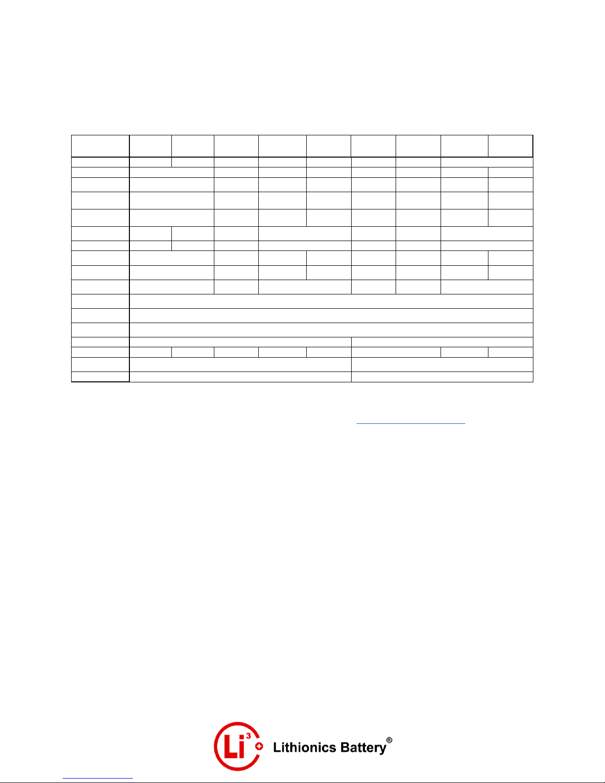
4.2 Charging
•The charging device(s) connected to the GT
Series Lithium Battery System must be
programmed as per Table 1.
•Charging may be performed at any time the
system is powered On.
oNOTE - The GT Series Lithium Battery System
will disconnect power if the voltage,
amperage, or temperature limits are
exceeded during charging.
oOnly use a Lithionics Battery approved
charging source. Please contact Lithionics
Battery for charger approval.
4.3 Initial Charging Cycle
•The initial charging cycle is required as it
calibrates the NeverDIE BMS to the Battery
Module for accurate State of Charge
percentage (SoC) monitoring.
•During the initial charging cycle the system
must reach a voltage level that is equal to the
Standard Full Charging Voltage indicated in
Table 1.
•Enable the charging device(s) so that they may
complete a charge cycle. It is recommended to
not have any discharge loads active during the
initial charging cycle, especially towards the
end of charging.
4.4 Discharging
•Discharging may be performed at any time the
system is powered On.
oNOTE - The GT Series Lithium Battery System
will disconnect power if the voltage,
amperage, or temperature limits are
exceeded during discharging.
•The NeverDIE feature allows the system to
have a “reserve” amount of energy left in the
battery. Once the system is discharged to 12.0V
or 10% State of Charge (SoC), whichever comes
first, power will be disabled to leave a “reserve”
amount of energy still left in the battery.
•To enable the remaining reserve energy of the
system, press the momentary Power/Reset
switch for 1 second.
oNOTE - Once the reserve range is enabled the
battery should be charged as soon as
possible.
oWARNING - If the reserve energy is used and
the battery module is left in a deeply
discharged state without immediate
charging, the battery module will become
permanently damaged.
4.4 System Storage Procedure
•Storing your battery at the correct
specifications is important as it keeps the
battery in the healthiest state possible for the
fastest deployment when needed.
•If the GT Series Lithium Battery System will not
be in use for greater than 2 weeks, it is
recommended to enable system storage.
•Storage mode is simply a fully charged system
in the Powered Off state.
•To enable System Storage:
oPerform a full charge cycle, ensure that the
System voltage reaches the Standard Full
Charging Voltage indicated in Table 1.
oPower off the System, press and hold the
Power/Reset switch for 3 seconds. Check that
the switch is no longer illuminated. Check