Lithionics Battery NeverDie Compact Series User manual

NeverDie® Compact Series 200 Internal BMS
MiniBMS
GTX12V315A-E2107-CS200 User Guide
Rev. A
®
TECHNOLOGY
®

Notice of Copyright
GTX12V315A-E2107-CS200 User Guide Copyright © 2021 all rights reserved. No part of this document may be reproduced in any form
without the express consent of Lithionics Battery®, Clearwater, FL 33765 USA. Lithionics Battery® reserves the right to revise this
document and make periodic changes to the contents without notice.
Index
Index.................................................................................................................................................................................................2
Overview..........................................................................................................................................................................................2
System Components........................................................................................................................................................................3
First Power-up..................................................................................................................................................................................4
Operation.........................................................................................................................................................................................4
Power Button with Status Light ......................................................................................................................................................5
Maintenance and Storage ...............................................................................................................................................................5
Bluetooth App..................................................................................................................................................................................6
Accessory Connector........................................................................................................................................................................8
Internal Heater Kit ...........................................................................................................................................................................9
BMS Functions .................................................................................................................................................................................9
Specifications ................................................................................................................................................................................ 10
Troubleshooting & FAQ ................................................................................................................................................................ 11
Contact Information ..................................................................................................................................................................... 11
Safety
▪All electrical work should be performed in accordance with local and national electrical codes.
▪Assume that voltage is present at the battery terminals, use insulated tools and gloves while working on the system.
▪Always turn off equipment connected to the battery in addition to turning OFF the Power button on the battery to isolate it from
other electrical circuits, before performing any repairs or maintenance on the system.
▪Always use proper wire sizes to connect the system to inverters, chargers, or other equipment.
▪Always use crimped connections to connect to the battery terminals.
▪Read and follow the inverter, charger, or other equipment manufacturers safety precautions prior to connecting the battery to
that equipment.
▪Always use charging equipment compatible with Lithium Iron Phosphate battery chemistry. See battery charging section below.
Overview
The purpose of this Owner’s Guide is to provide explanations and procedures for operating, maintaining, and troubleshooting the
GTX12V315A-E2107-CS200 battery. The GTX12V315A battery is a lithium iron phosphate (LiFePO4) chemistry battery with an internal
NeverDie® Compact Series 200 Battery Management System (BMS). The BMS monitors voltage, current and temperature of each cell
inside the battery and protects the battery from potential damage by disconnecting the battery circuit when the monitored
parameters go outside of the allowed limits. The BMS also transmits monitoring data over Bluetooth which allows customers to check
the battery data on their mobile device.

LITHIONICS BATTERY, 1770 CALUMET ST, CLEARWATER, FL 33765 USA
PH: 727.726.4204 | FAX: 727.797.8046 | WEB: LITHIONICSBATTERY.COM
Page 3of 11
System Components
The GTX12V315A-E2107-CS200 system ships with the following items:
•GTX12V315A-E2107-CS200 Battery
•Accessory Harness (#75-H1FCR-CS2)*
•Protective DC Terminal Covers (Red & Black)
•Two Sets of M8x1.25mm Bolts and Lock Washers for the Terminals
Wiring and bus bars are not included.
NOTE - It is recommended to keep the battery box and packaging material in case you need to return for service.
Reference
Feature
Description
A
Positive Terminal
Brass, Nickel Plated, M8-1.25 Thread, Torque to 60in-lbs/6.8Nm
B
Accessory Connector
FCC, Remote Power Button, CANbus RV-C
C
Negative Terminal
Brass, Nickel Plated, M8-1.25 Thread, Torque to 60in-lbs/6.8Nm
D
Power Button
Power Button with Status Light
E
Vent
Pressure Balancing Vent
F*
Accessory Harness
Enables Integration of FCC, Remote Power Button, and CANbus RV-C
*Accessory Harness is an optional part.
GTX12V315A-E2107-CS200 Battery
Accessory Harness
F

LITHIONICS BATTERY, 1770 CALUMET ST, CLEARWATER, FL 33765 USA
PH: 727.726.4204 | FAX: 727.797.8046 | WEB: LITHIONICSBATTERY.COM
Page 4of 11
First Power-up
The battery needs to be fully charged to 14.4V to condition the battery for use. Fully charging the battery calibrates the state-of-charge
percentage to be the most accurate and allows the cells to balance if necessary. The battery should be fully charged to 14.4V at least
once every 2 weeks.
Operation
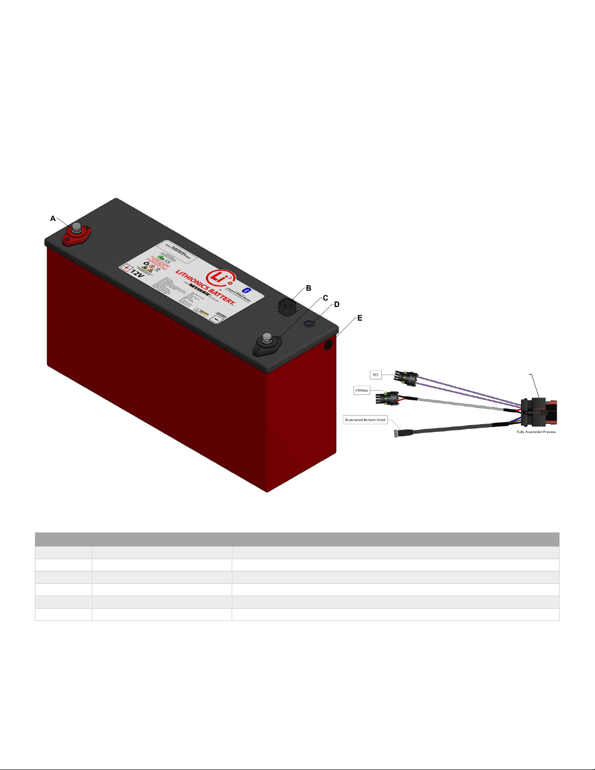
Before powering on, ensure the battery terminals are insulated and any connected devices are properly fused.
Due to shipping laws and regulations, your battery may be received at a partial state-of-charge (typically 50%). The battery needs to
be fully charged before use. This is necessary to calibrate the state-of-charge meter.
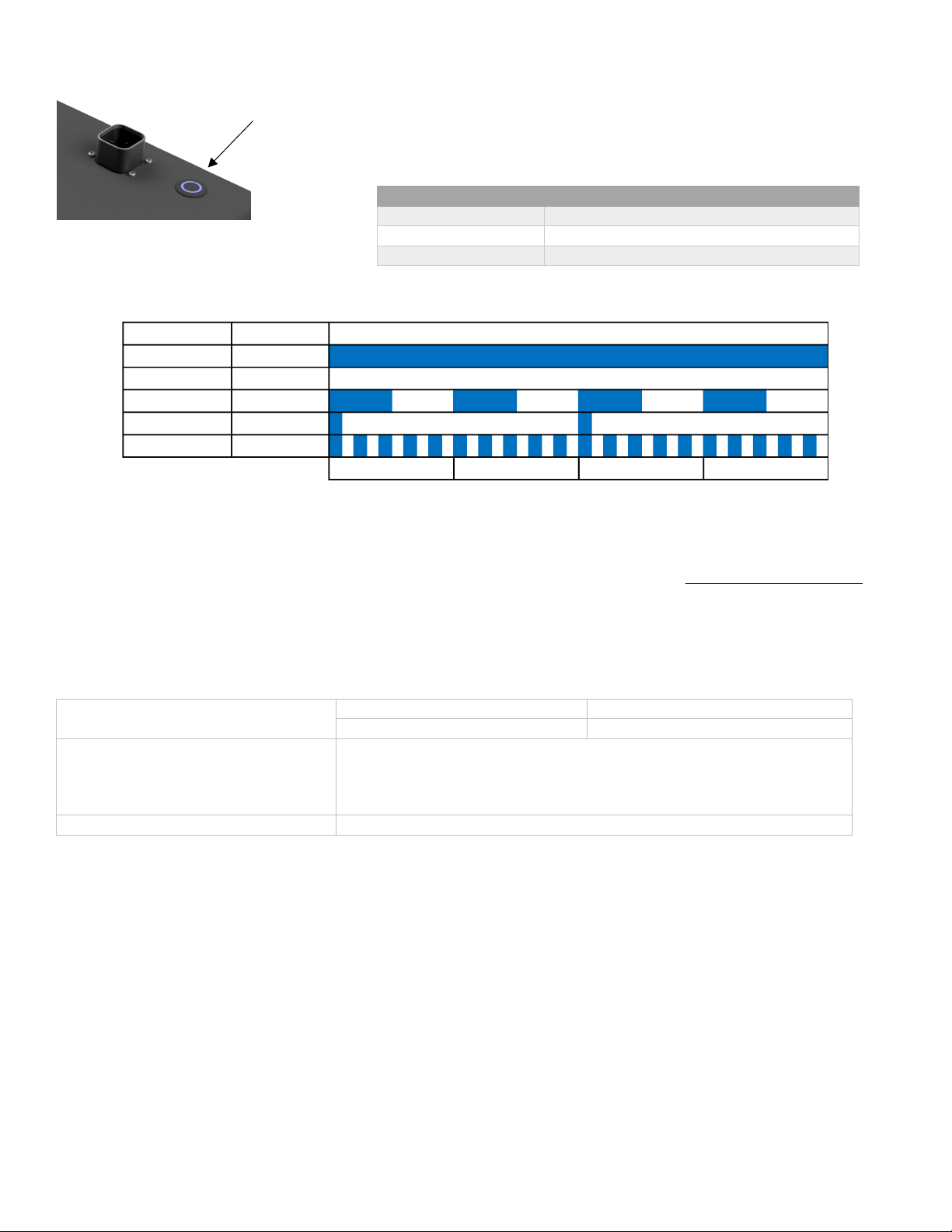
Powering the Battery On The power button is located on the battery lid and/or on the remote accessory harness extension. To turn
the battery on, press the power button for one second. The power button status light will illuminate solid on to confirm the battery is
powered on and operating normally.
Powering the Battery Off Be sure to shut down any high amperage loads prior to turning the battery off. To turn the battery off,
press and hold the power button for 3 seconds. The power button status light will turn off to confirm that battery power is off.
Resetting Power after a Protection Event If the battery detects a fault then it may turn power off. The battery can then be reset by
pressing the power button for one second.
Discharging Discharging may be performed at any time the system is powered On. The NeverDie® feature allows the system to
have a “reserve” amount of energy left in the battery. Once the system is discharged to approximately 12.0V or 10% state-of-charge,
whichever comes first, power will be off to leave a “reserve” amount of energy still left in the battery. The battery will also disconnect
power if the voltage, amperage, or temperature limits are exceeded during discharging. To enable the remaining reserve energy of
the system, press the BMS power button for 1 second. Once the reserve range is enabled the battery should be charged as soon as
possible. See page 9 BMS Functions for further details.
WARNING - If the reserve energy is used and the battery module is left in a deeply discharged state without immediate charging, the
battery module may become permanently damaged.
Charging The charging device(s) connected to the Lithium Battery System must be programmed per the recommended charge
settings below. Using an improper charger or charge settings could result in undesirable battery performance and accelerated wear.
The battery will disconnect power if the voltage, amperage, or temperature limits are exceeded during charging. Please note that
voltage rise during bulk charge stage is very slow, followed by a fast voltage rise at the end of charge. Once charge is completed, the
voltage drops down to a resting level. This behavior is normal and should not cause any concerns.
A lithium iron phosphate (described as LFP or LiFePO4) charger or
charging profile is required for battery charging. The battery
charge voltage should be set to 14.4V, equalization and
temperature compensation must be disabled, and if the charger
supports float mode, set it to 13.4 - 13.6V. If you are not sure if
your charger is suitable for charging your battery, contact
Lithionics Battery® or your dealer to confirm charger
compatibility, or to purchase compatible charger.
NOTE - Due to partial state-of-charge during storage and shipping, the cells inside the battery may not be perfectly balanced during
the first few charge cycles. You may observe some high voltage alerts and cell balancing status codes on the Lithionics Battery® Monitor
app, which indicate the balancing process is in progress. This is perfectly normal behavior and should not cause any concerns. After a
few full charge cycles the cells will balance out and these alerts will disappear. There is no adverse effect on battery operation, you
may continue to use the battery normally during these initial charge cycles.
Recommended Charge Settings
Recommended Bulk Charging Voltage
14.4V
Recommended Absorb Charging Voltage
14.4V
Recommended Absorb Cycle Time
30 Minutes
Maximum Absorb Cycle Time
60 Minutes
Recommend Float Voltage
13.4V
Maximum Float Voltage
13.6V
Equalization Mode
Disabled
Temperature Compensation
Disabled

LITHIONICS BATTERY, 1770 CALUMET ST, CLEARWATER, FL 33765 USA
PH: 727.726.4204 | FAX: 727.797.8046 | WEB: LITHIONICSBATTERY.COM
Page 5of 11
Power Button with Status Light
The BMS power button is located on the battery lid and includes a status light. You can also attach
the optional remote power button via the accessory harness. This can be useful if the battery is
installed in a location that is not easily accessible. The function and operation of the remote power
button remains the same as the main power button on the battery.
Refer to the table below for an explanation of the power button status light blink patterns.
Battery State Status Light
Powered On Solid ON
Powered Off Solid OFF
Charging Slow blink
Low Battery Short blink
Fault Alarm Rapid blink
Status Light pattern over time
< 1 second >
< 1 second >
< 1 second >
< 1 second >
Maintenance and Storage
Maintenance For optimal performance when in use, the battery should be fully charged to 14.4V at least once every 2 weeks.
Fully charging the battery calibrates the state-of-charge percentage to be the most accurate and allows the cells to balance if
necessary.
Storage Storing your battery at the correct specifications is important as it keeps the battery in the healthiest state possible.
Consult the table below for proper storage conditions.
Storage Temperature & Humidity Range
< 1 Month
-4~95°F (-20~35°C), 45~75%RH
< 3 Months
14~86°F (-10~30°C), 45~75%RH
Long Term Storage
If the battery needs to be stored for > 3 months the voltage should be 13.2V
(50% state-of-charge) and stored at the recommended storage specifications
shown above. Additionally, the battery needs at least one charge & discharge
cycle every six months.
Self-Discharge Rate
≤3% per month
Typical storage example < 1 month:
1. Fully charge the battery.
2. Turn the battery OFF using the battery power button.
3. Keep the battery in an environment according to the specifications shown above.
Typical storage example > 1 month, up to 3 months maximum:
1. Reduce the battery state-of-charge to 13.2V which is 50% ±10% state-of-charge.
2. Turn the battery OFF via the BMS power button.
3. Keep the battery in an environment according to the specifications shown above.
4. Every 3 months charge the battery to 100% state-of-charge, then discharge the battery to LVC, then charge it back to 50% ±10%
state-of-charge.
Power Button Operation
Power ON
Press for 1 Second
Power OFF
Press for 3 Seconds
Power Reset
Press for 1 Second (after protection event)

LITHIONICS BATTERY, 1770 CALUMET ST, CLEARWATER, FL 33765 USA
PH: 727.726.4204 | FAX: 727.797.8046 | WEB: LITHIONICSBATTERY.COM
Page 6of 11
Bluetooth App
Lithionics Battery® has developed the Lithionics Battery® Monitor app for iOS and Android mobile platforms, which allows real
time battery information. The battery must be turned on via the Power button before the Bluetooth connection can be made. When
the battery is turned off, Bluetooth is also powered off to save energy. This app can be downloaded for free on the Apple App Store
or the Google Play Store for your iOS 12.4+ or Android 5.0+ device.
To connect Bluetooth:
1) The battery must be in the ON position.
2) Bluetooth must be enabled on your device.
3) Open the Lithionics Battery® Monitor App and accept location permissions.
4) Under the Device List, select the battery you would like to monitor (the device name is
identified by the battery serial number).
Once the Bluetooth connection is made to the battery, the Battery Info section of the app
automatically displays. This section provides useful info such as the battery state-of-
charge percentage, voltage, current, power, internal cell temperature, BMS temperature,
power state and estimated time remaining. Clicking on the Status Code at the bottom
automatically opens the Status Code reader section.
The Status Code Reader section of the app makes it easy to visualize the status by
observing the color-coded table, see example to the left.
Each active description is color coded in green or red, where green indicates information
and red indicates faults or critical conditions requiring attention, such as immediate need
to charge the battery.

LITHIONICS BATTERY, 1770 CALUMET ST, CLEARWATER, FL 33765 USA
PH: 727.726.4204 | FAX: 727.797.8046 | WEB: LITHIONICSBATTERY.COM
Page 7of 11
The Bluetooth app can also be used to access the Firmware
Update section of the app. The BMS firmware version and
update status can be found in the settings menu when
connected to the Battery.
NOTE - The firmware update should only be performed if
necessary.
Additionally, the app provides automatic data logging
when connected to the battery. The log files can be found
under the settings menu and can be easily shared from the
app for troubleshooting or analyzing battery history.

LITHIONICS BATTERY, 1770 CALUMET ST, CLEARWATER, FL 33765 USA
PH: 727.726.4204 | FAX: 727.797.8046 | WEB: LITHIONICSBATTERY.COM
Page 8of 11
Accessory Connector
The battery accessory connector is located on the battery lid and is used to access the BMS’s
ported features. This allows implementation of the features listed below.
Mating cable extensions are available to integrate the accessory features.
Part Number
Feature
Description
75-149-180
FCC Extension
Dual Weatherpack Connector to Bare Wires, 15ft Length
75-224-196
Remote Power Button with Status Light
M8 Connector to Illuminated Remote Button, 16ft Length
The CANbus messages are formatted for compatibility with RV-C protocol. The CANbus protocol and supported messages are
documented and can be found at http://www.lithionicsbattery.com/user-guides.
Please contact Lithionics Battery® regarding options for mating CANBus connections.
Accessory Connector Pinout
Feature
Description
FCC
Field Control Circuit –For use with an alternator regulator
enable/disable circuit.
CANbus
RV-C CANbus Data
Remote Reset Button
For use with the Remote Power Button with Status Light
Pin
Description
1
Reset Button 1
2
Remote LED +
3
CAN Low
4
Remote LED -
5
CAN High
6
Reset Button 2
7
FCC 1
8
FCC 2
75-H1FCR-CS2 Accessory Harness

LITHIONICS BATTERY, 1770 CALUMET ST, CLEARWATER, FL 33765 USA
PH: 727.726.4204 | FAX: 727.797.8046 | WEB: LITHIONICSBATTERY.COM
Page 9of 11
Internal Heater Kit
The GTX12V315A-E2107-CS200 battery includes a thermostatically controlled heater kit to internally warm and maintain the battery
above 32F/0C. Keeping the battery’s internal temperature above 32F/0C ensures uninterrupted battery power and a longer battery
life.
Ambient Temperature
Average Power Used
Average Usage per Day
20F/-7C
9W
16.9Ah
-4F/-20C
21W
39.4Ah
NOTE - The internal heater kit will not activate if the battery is OFF.
BMS Functions
Below is a detailed description of advanced BMS features and how they affect the state of the battery. Some features depend on setup
parameters which are described in detail in the Configuration section of this user guide.
▪Power On/Off –In addition to the automatic disconnect protections, the battery can be manually turned off to disconnect
power at the terminals during installation, service, or storage.
▪Reserve Voltage Cutoff (RVC) –During discharge, the BMS will disable discharge current at approximately 10% state-
of-charge, or when any cell reaches 3.0V (approximately 12.0V total voltage). This allows the battery to store a small energy
reserve. Once the battery is in the RVC state you can use the reserve energy by a short-press of the power button.
oIt is recommended to charge the battery soon once it reaches RVC.
oThe battery will fully power off if it is not charged after sitting for 72 hours to further conserve its energy.
▪Low Voltage Cutoff (LVC) –During discharge, the BMS will disable discharge current when any cell reaches the 2.6V
(approximately 10.4V total voltage). Charging current is allowed, so that the battery can still be charged by a charging source.
Some charging sources require to “see” the battery voltage before allowing charging, in which case LVC lockout can be
temporarily overridden by short-pressing the Power button. This will allow the charger to sense the battery voltage, so
charging can begin.
oIt is recommended to charge the battery immediately once it reaches LVC.
oThe battery will fully power off if it is not charged after sitting 12 hours to further conserve its energy.
▪High Voltage Cutoff (HVC) –During charging, the BMS will disable charge current if any cell reaches 3.75V or higher
(approximately 14.8V total voltage). This should not happen during normal operation if the charging sources are setup with
correct charge settings. Once the charge current is removed the battery voltage will slowly lower and the BMS will
automatically disengage HVC.
▪Cell Temperature Based Cutoff –When the internal battery temperature goes below or above the temperature limits
the BMS will disable charge or discharge current to prevent further use of the battery until the temperature returns to safe
operating limits. Different temperature limits are enforced for charging and discharging due to the nature of LiFePO4
chemistry. Please see the specifications table below for temperature limits.
▪BMS Temperature Based Cutoff –When the BMS temperature goes above 180F the BMS will disable charge and
discharge current to prevent further use of the battery until the temperature lowers to below 160F.
▪Over Current Protection –The BMS will disable discharge or charge current if the amperage exceeds 300A for 2 minutes
continuously. To restore normal operation, remove/address the source of the overload, then short-press the Power Button.
▪Short Circuit Protection –The BMS will immediately disable discharge current if the current value exceeds 1200A. To
restore normal operation, remove/address the source of the short circuit, then short-press the Power Button.
NOTE - The lithium battery is capable of significant power output and may maintain the voltage level during a short circuit
event, producing a very large current capable of melting or welding connection points and damaging cables and connectors.
Even when the BMS detects the short circuit and tries to protect, the BMS may be damaged under such a large current. Make
sure that the battery connection is always properly fused and does not rely on the BMS alone for short circuit protection!
▪Internal Heater Kit –The internal heater kit will warm the battery when the cell temperature is 35F and lower and will
stop heating when the cell temperature is 40F and higher.

LITHIONICS BATTERY, 1770 CALUMET ST, CLEARWATER, FL 33765 USA
PH: 727.726.4204 | FAX: 727.797.8046 | WEB: LITHIONICSBATTERY.COM
Page 10 of 11
Specifications
Item
Description
Model
GTX12V315A-E2107-CS200
Nominal Voltage
12.8V
Nominal Capacity
315Ah
Nominal Watt Hours
4032
Internal Resistance
≤3mΩ
Features
NeverDie® Reserve, High and Low Voltage Cutoff, High and
Low Temperature Cutoff, Short Circuit Protection,
Bluetooth Telemetry, CANbus RV-C, FCC, Remote Button
NOTE: Battery may not be connected in series to make 24 volts or higher.
Charge
Charging temperature range
32~131°F (0~55°C)
Recommend Charge voltage
14.4V
Recommended float charge voltage (for standby use)
13.4V
Recommended charge current
≤160A
Allowed max charge current
250A with starting temp of 77°F (25°C)
Discharge
Discharging temperature range
-4~131°F (-20~55°C)
Output Voltage Range
10.4~14.6V
Recommended discharge current
≤200A
Max continuous discharge current
250A with starting temp of 77°F (25°C)
Surge discharge current
<600A for 30s max with starting temp of 77°F (25°C)
Pulse discharge current
<1200A for 1s max with starting temp of 77°F (25°C)
Reserve cut-off voltage
12.0V±0.05V
Discharge cut-off voltage
10.4±0.1V
Mechanical Characteristics
Dimensions
Length: 20.3in (516mm)
Width: 6.4in (163mm)
Height: 10.0in (254mm)
Mounting Orientation
Upright position only (terminals up)
Weight
Approx. 68lbs (30.8Kg)
Environmental Rating
IP66

LITHIONICS BATTERY, 1770 CALUMET ST, CLEARWATER, FL 33765 USA
PH: 727.726.4204 | FAX: 727.797.8046 | WEB: LITHIONICSBATTERY.COM
Page 11 of 11
Troubleshooting & FAQ
When troubleshooting your battery, one of the most helpful tools is the battery Status Code feature of the Lithionics Battery Monitor
App. If the battery shuts down due to a protective BMS feature, please have the Bluetooth app available when resetting the battery
to identify the battery info and status code. It can be helpful to screenshot the battery info screen, which will identify the battery
state-of-charge, voltage, current, temperature, and status code. The following status code descriptions can be used in correcting the
battery fault condition.
Frequently Asked Questions
1. The battery has been charging for a long time, why has it not reached 100%?
Depending on the charger output, charging could take several hours to complete. To confirm the battery is charging, check
the Bluetooth app to verify positive current is going into the battery. The voltage rise during bulk charge stage is very slow,
followed by a fast voltage rise at the end of charge to 14.4V. Once the battery reaches 14.4V, the State-of-Charge percentage
will calibrate to 100%. If no current is measured, confirm the charger is powered on, programmed correctly, and there are no
DC breakers or disconnect switches preventing power from transferring.
2. The battery is at 100%, why is it still charging?
It is normal for the charger to finish the charging cycle for a short period of time after the State-of-Charge percentage
calibrates to 100%. A 30-60 minute absorb cycle is recommended as the battery finishes charging and the charging current
reduced. The charger should then switch to a float charging mode at the battery resting voltage.
3. I have lost battery power, why did the battery turn off?
The battery has many automatic protections that could cause the battery to turn off. Most commonly, the battery will turn
off once you reach the 10% reserve range and just needs to be recharged. Using the Bluetooth app and Status Code can
provide you with helpful information for troubleshooting.
4. Why is the battery status light flashing?
The LED flash pattern can indicate if the battery is being charged, in a low voltage state, or experiencing a fault condition.
Reference the chart on page 5 for the status light pattern descriptions.
Contact Information
For technical or warranty support please first contact the dealer where the system was purchased.
Additionally, for factory support please send an email with your battery’s serial number to Support@LithionicsBattery.com
Description of Status Codes in the Lithionics Battery Monitor App
High Voltage State
The battery’s voltage is too high, typically 14.8V (3.75V per cell).
Cell Temp High/Low
The battery’s internal temperature is outside of the operating limits.
NeverDie® Reserve
The battery is in the NeverDie® Reserve State, allowing access to reserve energy.
BMS Temp High
The temperature of the BMS is too high, typically due to high charge or discharge current.
Reserve Range
The battery’s voltage is low (below 12.0V and/or 10%) and should be charged soon.
Low Voltage State
The battery’s voltage is very low (below 10.4V) and should be charged immediately.
Battery Overload
The charge or discharge current is over 300A and power will be turned off after 2 minutes.
Power Off State
The battery was turned off by the Power Button.
Overcurrent State
The discharge current has exceeded 600A, and power is now turned off.
Short Circuit Protection
The discharge current has exceeded 1200A, and power is now turned off.
Cell Over-Voltage
One of the battery’s cell voltages is too high.
Cell Under-Voltage
One of the battery’s cell voltages is too low.
BMS fault
A BMS fault is present.
Cell 1 Balancing
Cell 1 is balancing.
Cell 2 Balancing
Cell 2 is balancing.
Cell 3 Balancing
Cell 3 is balancing.
Cell 4 Balancing
Cell 4 is balancing.
This manual suits for next models
1
Table of contents
Other Lithionics Battery Camera Accessories manuals

Lithionics Battery
Lithionics Battery GT12V450A-F24 Guide

Lithionics Battery
Lithionics Battery GTO Series User manual

Lithionics Battery
Lithionics Battery GT12V525A-F24 User manual

Lithionics Battery
Lithionics Battery ionGen GTX12V315A-E2107-CS200RV VICTRON Assembly instructions

Lithionics Battery
Lithionics Battery GT Series User manual