Littelfuse PGR-3200 User manual
Tel: +1-800-832-3873
E-mail: techline@littelfuse.com
www.littelfuse.com
PGR-3200 MANUAL
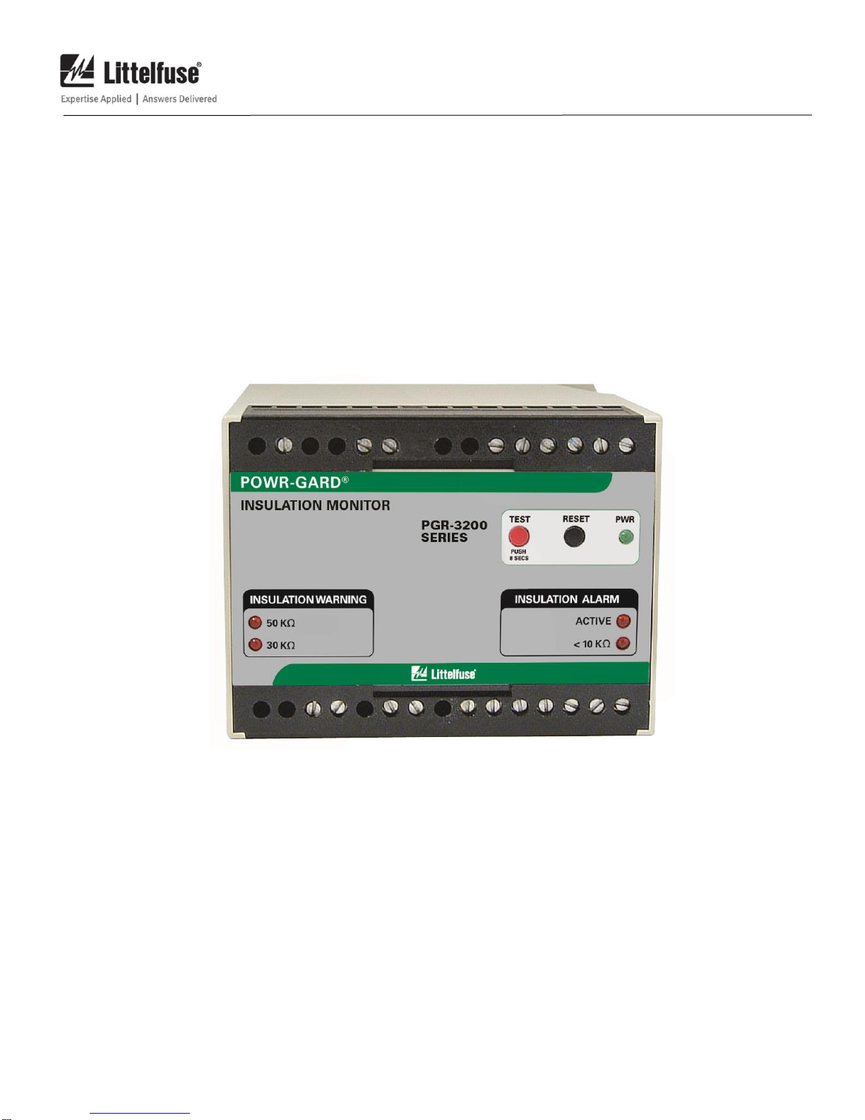
INSULATION MONITOR
REVISION 3-E-040918
Copyright © 2018 by Littelfuse, Inc.
All rights reserved.
Document Number: PM-1025-EN
Printed in Canada

PGR-3200 Insulation Monitor Page i
Rev. 3-E-040918
This page intentionally left blank.

PGR-3200 Insulation Monitor Page ii
Rev. 3-E-040918
TABLE OF CONTENTS
SECTION PAGE
1 General..........................................................................1
2 Operation......................................................................1
2.1 Relay Operating Mode.................................................1
2.2 Front-Panel Controls ....................................................1
2.2.1 Reset..................................................................1
2.2.2 Test ....................................................................1
2.3 Front-Panel Indication ..................................................1
2.3.1 Power.................................................................1
2.3.2 Insulation Warning...........................................1
2.3.3 Active................................................................1
2.3.4 Insulation Alarm...............................................1
2.4 Analog Output...............................................................1
2.5 RemoteReset ................................................................1
2.6 Remote Test...................................................................1
3 Installation....................................................................3
3.1 PGH-5000 and PGH-6000...........................................4
4 Technical Specifications............................................6
4.1 PGR-3200......................................................................6
4.2 PGH High-Tension Couplers......................................7
5 Ordering Information................................................7
6 Performance Test........................................................7
6.1 Insulation Test...............................................................7
Appendix A PGR-3200 Revision History...........................8
LIST OF FIGURES
FIGURE PAGE
1 PGR-3200 Outline and Mounting Details..................2
2 Connection Diagram for Ungrounded Systems
Under 1.3 kV.................................................................3
3 Connection Diagram for Ungrounded
5-kV Systems................................................................3
4 PGH-5000 Outline and Mounting
Details ............................................................................4
5 PGH-6000 Outline and Mounting
Details ............................................................................5
6 PGA-0510 Analog Ohm Meter...................................5
DISCLAIMER
Specifications are subject to change without notice.
Littelfuse, Inc. is not liable for contingent or consequential
damages, or for expenses sustained as a result of incorrect
application, incorrect adjustment, or a malfunction.

PGR-3200 Insulation Monitor Page iii
Rev. 3-E-040918
This page intentionally left blank.

PGR-3200 Insulation Monitor Page 1
Rev. 3-E-040918
1. GENERAL
The PGR-3200 Insulation Monitor measures phase-to-
ground resistance to detect electrical-insulation failure in
an ungrounded power utilization system. It provides three
levels of detection with a 50-kwarning with an LED and
output contact indication, a 30-kwarning with LED
indication, and a 10-kalarm with LED and output contact
indication. An analog output is provided for predictive
maintenance trending.
The PGR-3200 can be used to detect faults in
ungrounded systems up to 6 kV. It can be directly
connected to a system up to 1.3 kV, single or three phase,
50 or 60 Hz. A PGH-series high-tension coupler is
required for 5- and 6-kV systems.
2. OPERATION
The PGR-3200 actively monitors insulation resistance
when it is connected to the supply voltage. All conductors
connected to the monitored circuit are included in the
insulation measurement. See Fig. 2.
2.1 RELAY OPERATING MODE
The PGR-3200 output relays operate in the non-fail-safe
mode; they energize when an insulation warning or alarm
occurs.
2.2 FRONT-PANEL CONTROLS
2.2.1 RESET
The front-panel RESET switch is used to reset latching
trips. Cycling the supply voltage will also reset the PGR-
3200. See Section 2.5.
2.2.2 TEST
All LED’s will light and output relays will energize when
the TEST button is pressed for at least 8 s.
2.3 FRONT-PANEL INDICATION
2.3.1 POWER
The green LED’s labelled PWR indicates presence of
supply voltage.
2.3.2 INSULATION WARNING
The red LED’s labelled 50 kand 30 kwill light when
those respective insulation resistance values, or lower are
measured.
2.3.3 ACTIVE
The red LED labelled ACTIVE indicates the monitor is
enabled.
2.3.4 INSULATION ALARM
When insulation resistance measures 10 kor less, the
red LED labelled <10 kwill light.
2.4 ANALOG OUTPUT
A non-isolated, 0- to 1-mA output (terminals 25 and 26)
indicates insulation resistance. The metering output relates
to an insulation-resistance range of 0 to infinity using
optional meter PGA-0510. See Figs. 2, 3, and 6.
2.5 REMOTE RESET
When remote-reset terminals 18 and 19 (alarm) or 21 and
22 (warning) are connected, a warning or alarm remains
latched until theRESET switchis pressed or the remote-reset
terminals are momentarily opened.
If the remote-reset terminals are not connected, the
PGR-3200 operates in non-latching mode; a warning or
alarm will reset when the fault is removed.
2.6 REMOTE TEST
When terminal 29 is connected toground the monitor will
alarm. See Figs. 2 and 3. Response to a test input can take
several seconds.

PGR-3200 Insulation Monitor Page 2
Rev. 3-E-040918
FIGURE 1. PGR-3200 Outline and Mounting Details.
PGR-3200 Insulation Monitor Page 3
Rev. 3-E-040918
3. INSTALLATION
NOTE: Mounting, terminal-block connections, and
wiring must conform to applicable local electrical codes.
Check all applicable codes prior to installation.
The PGR-3200 can be surface or DIN-rail mounted.
See Fig. 1.
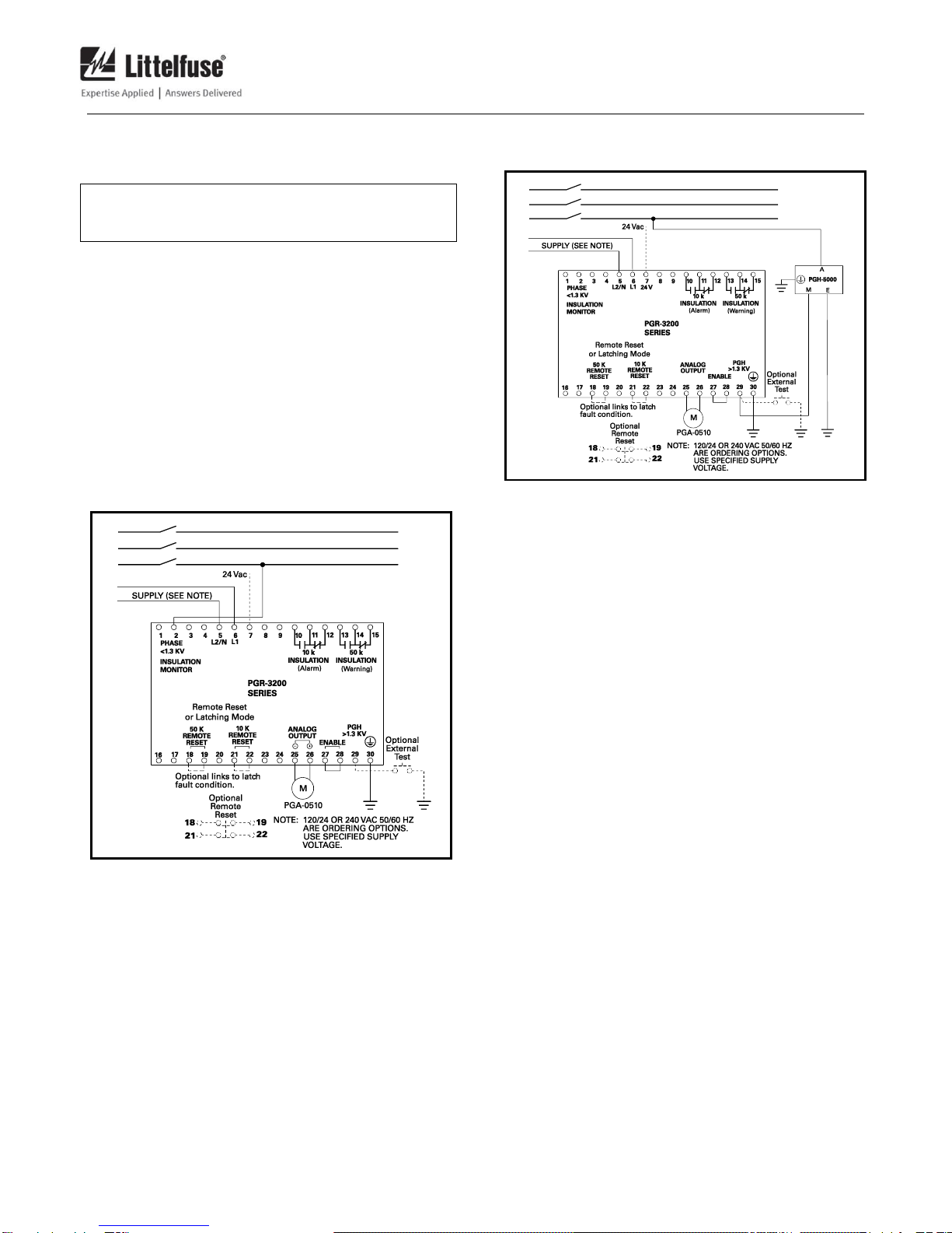
Use terminal 6 (L1) as the line terminal and terminal 5
(L2/N) as the neutral terminal. Connect terminal 30 to
ground.
Forsystems up to1.3kV, connect terminal 2 toonephase
on the load side of the starter.
Connect terminals for latching operation, remote reset,
and remote test as required. See Sections 2.5 and 2.6 and
Figs. 2and 3.
Connect an optional PGA-0510 Analog Ohm Meter to
terminals 25 and 26. Meter outline, dimensions, and cutout
size are shown in Fig. 6.
FIGURE 2. Connection Diagram for Ungrounded
Systems Under 1.3 kV.
FIGURE 3. Connection Diagram for Ungrounded
5-kV Systems.
PGR-3200 Insulation Monitor Page 4
Rev. 3-E-040918
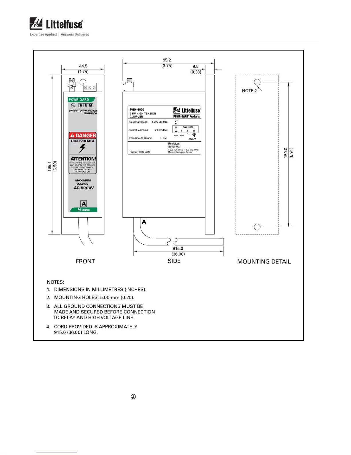
FIGURE 4. PGH-5000 Outline and Mounting Details.
3.1 PGH-5000 AND PGH-6000
For 5-kV and 6-kV systems, connect the PGR-3200 to the
monitored circuit with a PGH-5000 and PGH-6000
respectively. See Fig. 4 for PGH-5000 outlineand mounting
details. See Fig. 5 for PGH-6000 outline and mounting
details.
Connect protective-ground terminal ( ) to ground.
Connect terminal E to ground or to PGR-3200 terminal 30,
which must be grounded. Connect terminal M to PGR-
3200 terminal 29. (PGR-3200 terminal 2 is not used.) For
PGR-3200 to PGH-5000/PGH-6000 distances greater than
10 m (30’), use shielded cable, and connect the cable shield
to the second PGH-5000/PGH-6000 terminal E. Connect
terminal A to one phase on the load side of the motor
starter. See Fig. 3. The
PGH-5000/PHG-6000 includes 915 mm (36”) of high-
voltage conductor.

PGR-3200 Insulation Monitor Page 5
Rev. 3-E-040918
FIGURE 5. PGH-6000 Outline and Mounting Details.
FIGURE 6. PGA-0510 Analog Ohm Meter.

PGR-3200 Insulation Monitor Page 6
Rev. 3-E-040918
4. TECHNICAL SPECIFICATIONS
4.1 PGR-3200
Supply
120V option................................5VA,120Vac,24Vac
(+10, -15%)50/60 Hz
240 V option...........................5VA,240Vac,
(+10, -15%)50/60Hz
Maximum System Voltage:
Direct Connection:
UL Rating.........................600 Vac
Maximum .........................1,300 Vac
With PGH-5000.....................5,000 Vac
With PGH-6000.....................6,000 Vac
Measuring Voltage.......................12 Vdc
Measuring Current .......................20 A maximum
DC Resistance...............................600 k
AC impedance at 50-60 Hz.........> 1 M
Frequency Range..........................50 –20,000 Hz
Response-Level Settings .............10, 30, and 50 k(fixed)
Response Delay:
Warning, 10 krelay output:
Insulation Resistance
< 5 k.................................4 s
Insulation Resistance
= 10 k................................5 s
Alarm, 50 krelay output:
Insulation Resistance
< 25 k...............................2.5 s
Insulation Resistance
= 50 k...............................4.5 s
Analog Output:
Mode........................................Self Powered
Range.......................................0 to 1 mA
Impedance...............................6 kmaximum
Parameter................................0 to ∞ Ω Insulation
Resistance
Output Relays; Warning and Alarm:
Configuration..........................N.O. and N.C. (Form C)
Operating Mode .....................Non-Fail-Safe
UL Contact Rating.................5 A, 240 Vac resistive,
0.28 A, 30 Vdc resistive
Switching Capacity................1,200 VA
Supplemental Contact Ratings:
Carry Continuous................5 A, maximum
Trip Mode Latching or Autoreset
Reset ..............................................Front-Panel Button and
Remote N.C. Contacts
Test................................................Front-Panel Button and
Remote N.O. Contact
Terminals......................................Wire Clamping,
22 to 12 AWG
(0.3 to 3.3 mm2)
conductors
Tightening Torque.............0.40 N∙m (3.54 lbf∙in)
Conductor Type...................Copper, Solid or
Stranded with
Ferrules
Conductor Rating................60/75°C
Dimensions:
Height......................................75 mm (3.0”)
Width ......................................100 mm (3.9”)
Depth.......................................113 mm (4.4”)
Including DIN rail..............115 mm (4.5”)
Shipping Weight..........................0.45 kg (1 lb)
Environment:
Operating Temperature.........-10 to 60°C (14 to 140°F)
Storage Temperature.............-40 to 80°C (-40 to 176°F)
Humidity.................................85% Non-Condensing
Enclosure Rating....................lP20
Altitude...................................2,000 m (6,562 ft)
maximum
Overvoltage Category...........II
Pollution Degree....................2
Certification..................................UL Listed
UL508 Industrial Control
Equipment
FCC
RoHS

PGR-3200 Insulation Monitor Page 7
Rev. 3-E-040918
4.2 PGHHIGH-TENSION COUPLERS
Maximum LineVoltage:
PGH-5000...............................5,000 Vac
PGH-6000............................6,000 Vac
Current to Ground.....................2.5 mA maximum
Terminal M Maximum
Voltage......................................50 Vac
Terminals:
E, E, and M ......................Wire Clamping,
26 to 12 AWG
(0.13 to 3.3 mm2)
conductors
Tightening Torque ...........0.50 N∙m (4.43 lbf∙in)
......................................Wire Clamping,
10 AWG (5.3 mm2)
maximum
High Tension Lead A................8 AWG (8.4 mm2),
40 kVdc, 915 mm (36”)
5. ORDERING INFORMATION
PGA-0510.....................................Analog Ohm Meter
PGH-5000.....................................5 kV High Tension
Coupler
PGH-6000.....................................6 kV High Tension
Coupler
NOTES:
(1) UL not available for this supply option.
6. PERFORMANCE TEST
6.1 INSULATION TEST
Perform this test with the starter open and appropriate
lock-out procedures.
Connect a 20 kresistor between one phaseand ground
at the line side of the starter or motor terminal box. Select
a phase that is not connected to PGR-3200 terminal 2 (or
the PGH-5000 or PGH-6000). The
PGR-3200 will indicate a warning by lighting the 50 k
and 30 kLED’s and energizing the 50 kinsulation
relay.
Replace the 20-kresistor with an 8 kresistor.
The PGR-3200 will indicate an alarm by lighting the
< 10 kLED and energizing the 10 kinsulation relay.

PGR-3200 Insulation Monitor Page 8
Rev. 3-E-040918
APPENDIX A
PGR-3200 REVISION HISTORY
MANUAL
RELEASE DATE
MANUAL
REVISION
PRODUCT REVISION
(REVISION NUMBER ON PRODUCT LABEL)
April 9, 2018
3-E-040918
01
November 19, 2015
3-D-111915
August 4, 2015
3-C-080415
MANUAL REVISION HISTORY
REVISION 3-E-040918
SECTION 4
Specifications added.
REVISION 3-D-111915
SECTION 4
Terminal torque specifications added.
REVISION 3-D-111915
SECTION 4
Terminal torque specifications added.
SECTION 5
Ordering information updated.
REVISION 3-C-080415
Model name changed to Insulation Monitor.
SECTION 3
Figs. 4, 5, and 6 updated.
SECTION 4
Output relay, dimension, and environment specifications updated.
Certifications updated.
Section 4.2 added.
SECTION 5
Ordering information updated.
APPENDIX A
Revision history added.
PRODUCT REVISION HISTORY
PRODUCT REVISION 01
UL Certification.
Table of contents
Other Littelfuse Microphone manuals


Popular Microphone manuals by other brands


Sennheiser
Sennheiser MKH 40 P 48 Instructions for use

Mobility Sound
Mobility Sound WTX-583-DUAL quick start

Takstar
Takstar TA-55D quick start guide

Solid State Logic
Solid State Logic SSL CONNEX quick start guide

Sennheiser
Sennheiser HM 35 Instructions for use

Sennheiser
Sennheiser SKM 5200-II instruction manual


