manuals.online logo
Brands
  1. Home
  2. •
  3. Brands
  4. •
  5. Littfinski Daten Technik
  6. •
  7. Media Converter
  8. •
  9. Littfinski Daten Technik Digital Professional Series User manual

Littfinski Daten Technik Digital Professional Series User manual

Littfinski DatenTechnik (LDT)
Operating Instruction
Light signal decoder
for light-signals with LED
from the Digital-Professional-Series !
LS-DEC-SBB-F Part-No.: 513012
>> finished module <<
Suitable for the digital systems:
Märklin-Motorola and DCC
For digital control of:
⇒up to two Swiss SBB signals with 5 or 7 lamps
⇒signals can be switched together or independent
⇒for LED-signals with common anode or cathode
Realistic operation of the signal aspects by implemented
dimming function and dark phase between the signal
aspects.
This product is not a toy! Not suitable for children under 14 years of age!
The kit contains small parts, which should be kept away from children under 3!
Improper use will imply danger of injuring due to sharp edges and tips! Please
store this instruction carefully.
white point
Introduction/Safety instruction:
You have purchased the light signal decoder LS-DEC-SBB for your
model railway as a kit or as finished module.
The LS-DEC is a high quality product that is supplied within the Digital-
Professional-Series of Littfinski DatenTechnik (LDT).
We are wishing you having a good time using this product.
The light signal decoder LS-DEC of the Digital-Professional-Series
can be easily operated on your digital model railway.
By using a connector plug bridge you can choose if you want to
connect the decoder to a Märklin-Motorola system or to a digital
system with DCC standard.
The finished module comes with a 2 years limited warranty.
•Please read the following instructions carefully. Warranty will expire
due to damages caused by disregarding the operating instructions.
LDT will also not be liable for any consequential damages caused by
improper use or installation.
Connecting the decoder to your digital model railway
layout:
•Attention: Before starting the installation-work switch off the
layout voltage supply (switch-off the transformers or disconnect
the main supply).
The Light signal decoder LS-DEC is suitable for the DCC data format
as used e.g. by Lenz-Digital Plus, Roco-Digital (switching via
Keyboard or multiMAUS only; switching via Lokmaus 2® and R3® is
not possible), Zimo, LGB-Digital, Intellibox, TWIN-CENTER,
DiCoStation, ECoS, EasyControl, KeyCom-DC and Arnold-Digital /
Märklin-Digital= whenever no connector plug bridge is inserted in
position J2.
The decoder is suitable for Märklin-Digital~ / Märklin Systems or
Märklin-Motorola (e.g. Control-Unit, Central Station, Intellibox,
DiCoStation, ECoS, EasyControl, KeyCom-MM) if you insert a
connector plug bridge on J2.
The decoder receives the digital information via the clamp KL2.
Connect the clamp with a rail or even better connect the clamp directly
to the command station or a booster assuring the supply of digital
information free from any interference.
Please attend to the marking on clamp KL2. The colors 'red' and
'brown' next to the clamp are usually used by Märklin-Motorola
systems (e.g. Märklin-Digital~ / Märklin Systems / Intellibox).
D3 C3
C7
R1
4N25
IC3
R13
J1
CR1
24C01
IC2
L1
C5 C4
Z86E3016
C6
R2 R6
R4
R3
R8
R7
R12
R9
R11
R10
J2
S1
D2
KL6
LM2574
IC4
D1
KL5 KL3KL7
KL8KL9KL10
KL2
KL4
KL1
AK DCCMM
A B Rev. 3.2
Littfinski DatenTechnik (LDT)
br.
rot
LS-DEC
Lichtsignal-Decoder
ws
ge
gn
rt2
rt1
gn2
gn1
ge2
ge1
+
5V
-
ws
ge
gn
rt2
rt1
gn2
gn1
ge2
ge1
+
5V
-
14..18V~
J
K
BR1
Lenz-Digital systems are using the letters 'J'and 'K'.
In case you assemble the decoder to an Arnold-Digital (old) or
Märklin-Digital= system, you have to connect 'black' to 'K' and 'red' to
'J'.
The decoder receives the power supply via the two poles clamp KL1.
The voltage shall be in a range of 14..18V~ (alternate voltage output of
a model rail road transformer).
If you do not want to supply voltage separately from a transformer to
the LS-DEC decoder you can shorten the clamp KL1 and KL2 with
two wires. In this case the decoder will get the power supply
completely from the digital network.
Connecting the signals:
General:
Up to 2 signals with 5 or 7 lamps can be connected to the light signal
decoder LS-DEC.One signals per clamp block. The build up of the two
clamps is identical. The following description refers mainly to one clamp
only. As you can see on the identical marking the description is also
valid for the second clamp.
Common connection:
All LED-signals of any manufacturer are designed in accordance to the
same principle. One wire of all light emitting diodes of a signal will be
generally connected to a common wire. Depending if all anodes or all
cathodes are connected together the signals will be called as common
anodes-respectively common cathodes-signal.
If you use signals with common anodes you have to clamp this wire to
the connection marked '+'. In addition you shall not insert the
connection plug bridge in J1 in this case.
If you use signals with common cathodes you have to clamp this wire
to the connection marked '-'. In addition you shall insert the
connection plug bridge in J1 in this case.
The second connection of each light diode is separated and mostly
color marked at the end and contains a series resistor.
Series resistor:
Light emitting diodes have always to be operated with a suitable
series resistor to prevent that they will be destroyed. For this
prevention all outputs have already a series resistor of 330 Ohm
integrated on the printed circuit board of the light signal decoder
LS-DEC. Is there no further external resistor the diode-current will be
about 10mA.
This provides sufficient brightness. In case your light diodes are to
bright you can correct the brightness by assembling external resistors
of some 100 Ohms to your personal requirement.
For assigning the single cables of the light diodes to the correct
clamp connection please attend to the below signal images. The
marks next to signal light diodes are not corresponding to the actual
light color but to the marking of the connection at the light signal
decoder LS-DEC.
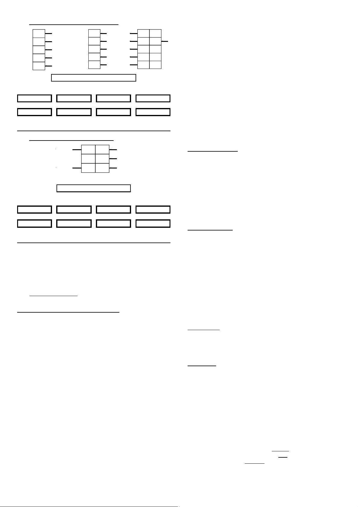
1. Home signal with 5 or 7 lamps:
GN1
RT1
GE1
GN2
GE
WS
GE1
GN2
RT1
GN1
RT1
WS
GE1
GN2
GE
GN1
home signal with 5 or 7 lamps
H2 3
train stop 40km/h 65km/h
red red red red
1234
green green green green
proceed 95km/h 40km/h
15 6
2. Advance signal with 5 lamps:
WS
GN1 oder GN
RT1GE1 oder GE2
RT2 oder GN2
There are three wire bridges required. Connect GN1 with GN, RT2 with
GN2 and GE1 with GE2.
advance signal with 5 lamps
H2 3
train stop 40km/h 65kmh (dark switch)
red red red red
1234
green green green green
proceed 95km/h 40km/h
15 6
If you do not know the correct allocation of the single wires to the light
emitting diodes you can test the function by connecting the wires to
clamp RT1 or RT2. These outputs are active because the decoder
switches all signals to red after switching on.
Further sample connections are available at the internet on our Web-
Site (www.ldt-infocenter.com) under "Downloads". Please load the file
"LSDEC-SBB_INFO_engl" onto your PC.
Programming the decoder address:
•Switch on the power supply of your model rail way.
•Activate the programming key S1. Do not touch the integrated
circuits of the pc-board because any electrostatic discharge can
destroy the IC`s.
•At least two light emitting diodes on a signal connected to the
left clamp block will be automatically switched over every 1,5
seconds in a flashing mode. This indicates that the decoder is in
the programming mode.
•The decoder addresses for magnet accessories also to be used for
switching the signal-aspects are combined into groups of four.
The address 1 to 4 build the first group. The address 5 to 8 build the
second group etc. In accordance to the operation mode 4 or 8
addresses will be assigned to the decoder. At the mode "single
function" both signals connected to the light signal decoder can
be operated absolute independent. The decoder requires for the
operation mode 8 addresses (4 addresses for each clamp bar).
At the "master/slave-function" both signals will be switched with
one command. Therefore will it be possible e.g. to switch home-
and advance signals together. In this operation mode the light
signal decoder requires only 4 addresses.
The operation mode has to be entered together with the decoder
address. If you activate during address-programming a key of the
required group of four which would switch a turnout straight or a
signal to green the decoder will go into the "single function
mode". If you activate a key which would switch a turnout round or
switch a signal to red you choose therefore the "function
master/slave".
•If the decoder has recognized the assignment correctly the
connected light emitting diode will flash a little faster. Afterwards
the flashing slows down to the initial 1,5 seconds again.
In case the decoder will not recognize the address it could be that
the two digital information connections (clamp2) are wrong
connected. For testing this, switch off the power supply, exchange
the connection on KL2 and start addressing again.
•Press now the programming key S1 again. Have you chosen the
operation mode "master/slave function" the decoder will leave the
programming mode because the programming of the group of four
has been completed. All signals will be automatically switched to
stop. The "master/slave function"has now been completed.
Have you chosen the operation mode "single function"you have
assigned the address group of the left clamp bar with the first
programming step. Therefore two light emitting diodes will flash
at the signal connected to the right clamp bar. Now activate any
key of the address group assigned for this signal. The decoder will
confirm the programming with a faster flashing.
Then press the programming key S1 again. The programming for
the "single function" has now been completed. Both connected
signals will switched to STOP by the decoder.
Signal switching:
Below the drafts of the above signal aspects you can find a respective
key-group for the addresses 1 to 4 and the corresponding keys 'red'
and 'green'. Additionally is the meaning of the signal position indicated
above or below. The addresses 1 to 4 are indicated as a sample only.
The actual addresses are corresponding to the assignment of the clamp
bar you choose during programming.
If you have connected an advance-and an exit-signal to one of the two
clamp bars (as shown at the first sample) you can switch with the
address 1 and the key green the exit signal to proceed (1).
The light emitting diode marked with GN will now indicate this at the
signal.
Dark switching:
In case a home-and an advance-signal are on one common signal
post the advance-signal can remain dark if the home-signal
indicates H or 6.
To activate the dark-switching-mode switch the home signal to Hor
6. If you press now the key 4 'red'you can switch the advance-signal-
aspect to 'on'respectively to 'off'with each keystroke. If the advance-
signal is in 'off'position the dark-switching mode is activated. The light
signal decoder stores this mode permanently as well as the
programmed addresses. All programmed modes can be changed at
any time.
Advance signal aspects received during the signal has been switched to
dark will be indicated whenever the exit signal has been switched to 1,
2, 3 or 5.
Accessory:
For easy assembly of the printed circuit board below your model rail
road layout base plate we offer a set of assembly material under the
order identification: MON-SET. Under LDT-01 you can purchase a low
priced durable case for the LS-DEC.
Attention:
The Light signal decoder LS-DEC switches the signal aspect not just
quickly on and off but is dimming the light emitting diodes realistic up
and down. Even between the signal aspects a short off-phase is
provided. Further digital commands received during this switch-over-
time of about 0,4 seconds will not be taken up from the decoder. Please
take care that the switching-commands are not in a to fast sequence.
The impression is absolutely realistic if the switching is considerable
slow.
Made in Europe by
Littfinski DatenTechnik (LDT)
Kleiner Ring 9
D-25492 Heist/Germany
Phone: 0049 4122 / 977 381
Fax: 0049 4122 / 977 382
Internet: http://www.ldt-infocenter.com
Subject to technical changes and errors. 10/2007 by LDT
Märklin and Motorola are registered trade marks.

This manual suits for next models

2

Other Littfinski Daten Technik Media Converter manuals

Littfinski Daten Technik S-DEC-4-MM-B User manual

Littfinski Daten Technik

Littfinski Daten Technik S-DEC-4-MM-B User manual

Littfinski Daten Technik LS-DEC-8x2-B User manual

Littfinski Daten Technik

Littfinski Daten Technik LS-DEC-8x2-B User manual

Littfinski Daten Technik SA-DEC-4-MM-B User manual

Littfinski Daten Technik

Littfinski Daten Technik SA-DEC-4-MM-B User manual

Littfinski Daten Technik SA-DEC-4-MM-F User manual

Littfinski Daten Technik

Littfinski Daten Technik SA-DEC-4-MM-F User manual

Littfinski Daten Technik SA-DEC-4-MM-B User manual

Littfinski Daten Technik

Littfinski Daten Technik SA-DEC-4-MM-B User manual

Littfinski Daten Technik 1-DEC-DC-B User manual

Littfinski Daten Technik

Littfinski Daten Technik 1-DEC-DC-B User manual

Littfinski Daten Technik LS-DEC-BR-F User manual

Littfinski Daten Technik

Littfinski Daten Technik LS-DEC-BR-F User manual

Littfinski Daten Technik S-DEC-4-DC-B User manual

Littfinski Daten Technik

Littfinski Daten Technik S-DEC-4-DC-B User manual

Littfinski Daten Technik TurnTable-Decoder Technical manual

Littfinski Daten Technik

Littfinski Daten Technik TurnTable-Decoder Technical manual

Littfinski Daten Technik 510711 User manual

Littfinski Daten Technik

Littfinski Daten Technik 510711 User manual

Littfinski Daten Technik 210311 User manual

Littfinski Daten Technik

Littfinski Daten Technik 210311 User manual

Popular Media Converter manuals by other brands

VAD DAC-10 user manual

VAD

VAD DAC-10 user manual

OWI C-195-OWI Service manual

OWI

OWI C-195-OWI Service manual

SMC Networks EZ Connect user guide

SMC Networks

SMC Networks EZ Connect user guide

CTC Union IMC-1000M user manual

CTC Union

CTC Union IMC-1000M user manual

Lindy 38165 user manual

Lindy

Lindy 38165 user manual

Atlona AT-LINE-PRO2 user manual

Atlona

Atlona AT-LINE-PRO2 user manual

MRC 0001822 quick start guide

MRC

MRC 0001822 quick start guide

True blue power TC230 Installation manual and operating instructions

True blue power

True blue power TC230 Installation manual and operating instructions

ATEN UC-232A user manual

ATEN

ATEN UC-232A user manual

ADL GT40a Q&A

ADL

ADL GT40a Q&A

Keyautomation 900EGKD2 Instructions and warnings for installation and use

Keyautomation

Keyautomation 900EGKD2 Instructions and warnings for installation and use

TR-Electronic LP-46 Series user manual

TR-Electronic

TR-Electronic LP-46 Series user manual

Vivo Link VLHDMISP1X4 user manual

Vivo Link

Vivo Link VLHDMISP1X4 user manual

ICP DAS USA ZT-2570 manual

ICP DAS USA

ICP DAS USA ZT-2570 manual

Optimus MI2-700ETH Installation and operating instructions

Optimus

Optimus MI2-700ETH Installation and operating instructions

Block V-250 LTD manual

Block

Block V-250 LTD manual

Black Box ServSensor JR EME102A user manual

Black Box

Black Box ServSensor JR EME102A user manual

IFM DP1222 operating instructions

IFM

IFM DP1222 operating instructions

manuals.online logo
manuals.online logoBrands
  • About & Mission
  • Contact us
  • Privacy Policy
  • Terms and Conditions

Copyright 2025 Manuals.Online. All Rights Reserved.