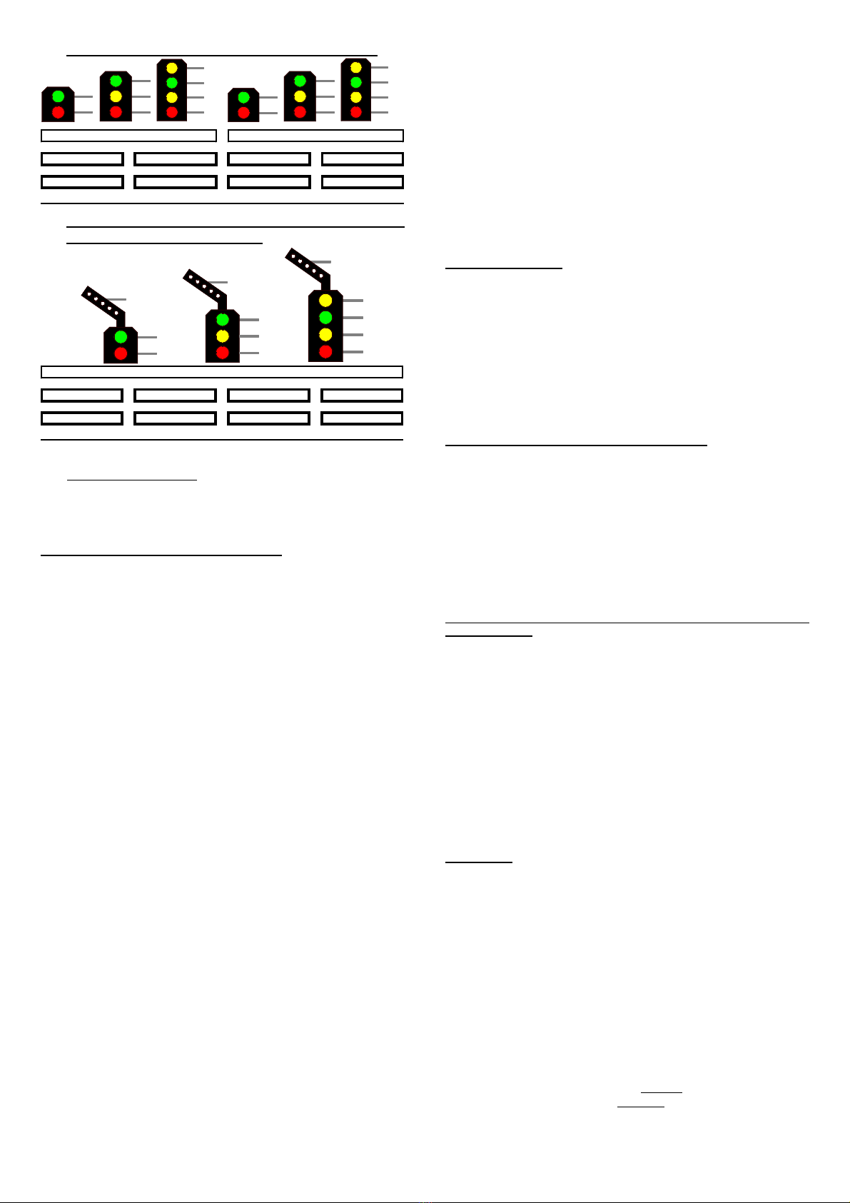
1. Two 2- to 4-aspect signals on each clamp bar:
GN
RT1
GN
GE
RT1
RT2
GN
GE
RT1
GN1
GN2
GN1
GE1
GN2
GE2
GN1
GE1
GN2
2. One 2- to 4-aspect Signal with direction indicator
(Feather) for each clamp bar:
GE1
GN
RT1
GN
GE
RT1
GE1
RT2
GN
GE
GE1
RT1
Signal with direction indicator (Feather)
Further sample connections are available at the internet on our Web-
Site (www.ldt-infocenter.com) at the section “Sample Connections”.
Additionally you can find detailed information about the Light-Signal
Decoder LS-DEC-BR at our Web site within the section “Digital-
Compendium”.
Programming the decoder address:
•The jumper J3 has to be inserted for the programming of the
decoder addresses.
•Switch-on the power supply of your model rail way.
•Activate the programming key S1.
•At least two light emitting diodes on a signal connected to the left
clamp block (on this decoder side is the programming key S1) will
be automatically switched over every 1.5 seconds in a flashing
mode. This indicates that the decoder is in the programming mode.
•Press now one key of the fourfold address-group to be assigned
to the left clamp block of the decoder. For programming the decoder
address you can as well release a turnout switch signal via your
model railway software.
Remarks: The decoder addresses for magnet accessories also
to be used for switching the signal-aspects are combined into
groups of four. The address 1 to 4 will be the first group. The
address 5 to 8 will be the second group etc. Each clamp block of a
LS-DEC decoder can be assigned to any of these groups. It does not
matter which of the eight possible keys used for programming will be
activated. The decoder stores always the complete group of keys.
If the Light-Signal Decoder LS-DEC shall control on this clamp bar
two 2 to 4 aspect signals or one 2 to 4 aspect signal with
direction indicator (Feather) this has to be adjusted together with
the decoder address. If you activate within the programming mode
one key of the desired group of four keys designated for switching a
turnout straight or a signal to green the decoder will be set for the
controlling of two 2- to 4- aspect signals.
If you activate a key for switching a turnout round or a signal to red
you have selected the option to switch one 2- to 4-aspect signal
with direction indicator (Feather). For both programming modes
(left and right clamp bar) you can individual select if two 2- to 4-
aspect signals or one 2- to 4-aspect signal with direction
indicator (Feather) shall be digital controlled.
•If the decoder has recognized the assignment correctly the
connected light emitting diode will flash a little faster. Afterwards
the flashing slows down to the initial 1.5 seconds again.
In case the decoder will not recognize the address it could be that the
two digital information connections (clamp 2) are wrong connected.
For testing this, switch off thepower supply, exchange the connection
on KL2 and start addressing again.
•Press now the programming key S1 again. At least two light
emitting diodes connected to the right clamp block will flash now.
Repeat the programming of this fourfold-address block as
described above.
•Now press the programming key S1 a third time for leaving the
programming mode. All signals will be automatically switched to
STOP.
Signal switching:
The opposite sample connections show how the fourfold address-
group can be set by use of 8 keys of the push button panel for setting
the turnouts or signals. Between each pair of keys are e.g. the addresses
1 to 4. The two keys red and green for each address are assigned to
the turnout position round or straight respectively the corresponding
signal aspect which is indicated above or below key.
The actual address section is related to which fourfold address-group
has been selected during the programming.
If you use a remote control LH100 of Company Lenz Elektronik then
red will be the minus key and green the plus key.
1. Two 2- to 4-aspect signals on each clamp bar:
If you have adjusted the Light-Signal Decoder LS-DEC-BR for switching
two 2- to 4-aspect signals by programming one clamp bar as shown
at picture left under 1you can e.g. switch the first signal to drive with
address 1 and key green.
The LED marked with GN indicates this at the first signal.
Please activate the key green of the address 3 and the second signal
will be switched to drive. The LED marked with GN1.
The first signal will be always switched via the address 1 and 2. The
second signal of the clamp bar will be switched via the address 3 and
4of the programmed four fold address group.
2. One 2- to 4-aspect signal with direction indicator (Feather) on
each clamp bar:
If you have adjusted the LS-DEC-BR by programming the address of
one clamp bar for switching one 2- to 4-aspect signal with direction
indicator (Feather) the picture left under 2 will indicate the status.
Via the two first addresses of the clamp bar of this programmed four
fold address group is it possible to switch the four signal aspects. At
the sample 2 this will indicate the addresses 1 and 2.
Via the third address of the programmed four fold address group is it
possible to switch the direction indicator (Feather) on or off. The
direction indicator (Feather) will lighten exemplary only if one of the
three drive aspects will be indicated. If the signal indicates stop the
direction indicator (Feather) will not lighten.
For the signal aspects drive slow and drive medium is it possible to
switch the function flashing on or off via the fourth address of the
programmed four fold address group.
Attention:
The Light-Signal Decoder LS-DEC switches the signal aspects not just
on and off but is dimming the light emitting diodes realistic up and down.
Even between the signal aspects a short off-phase is provided. Further
digital commands received during this switch-over-time of about 0.4
seconds will not be taken up from the decoder. Please take care that the
switching-commands are not in a to fast sequence. The impression is
absolutely realistic if the switching is considerable slow.
If the jumper J3 will be removed after programming of the decoder
addresses the memory storage of the Light-Signal Decoder LS-DEC
will be protected against any alteration. Made in Europe by
Littfinski DatenTechnik (LDT)
Bühler electronic GmbH
Ulmenstraße 43
15370 Fredersdorf / Germany
Phone: +49 (0) 33439 / 867-0
Internet: www.ldt-infocenter.com
Subject to technical changes and errors. 05/2019 by LDT
Märklin and Motorola are registered trademarks.


