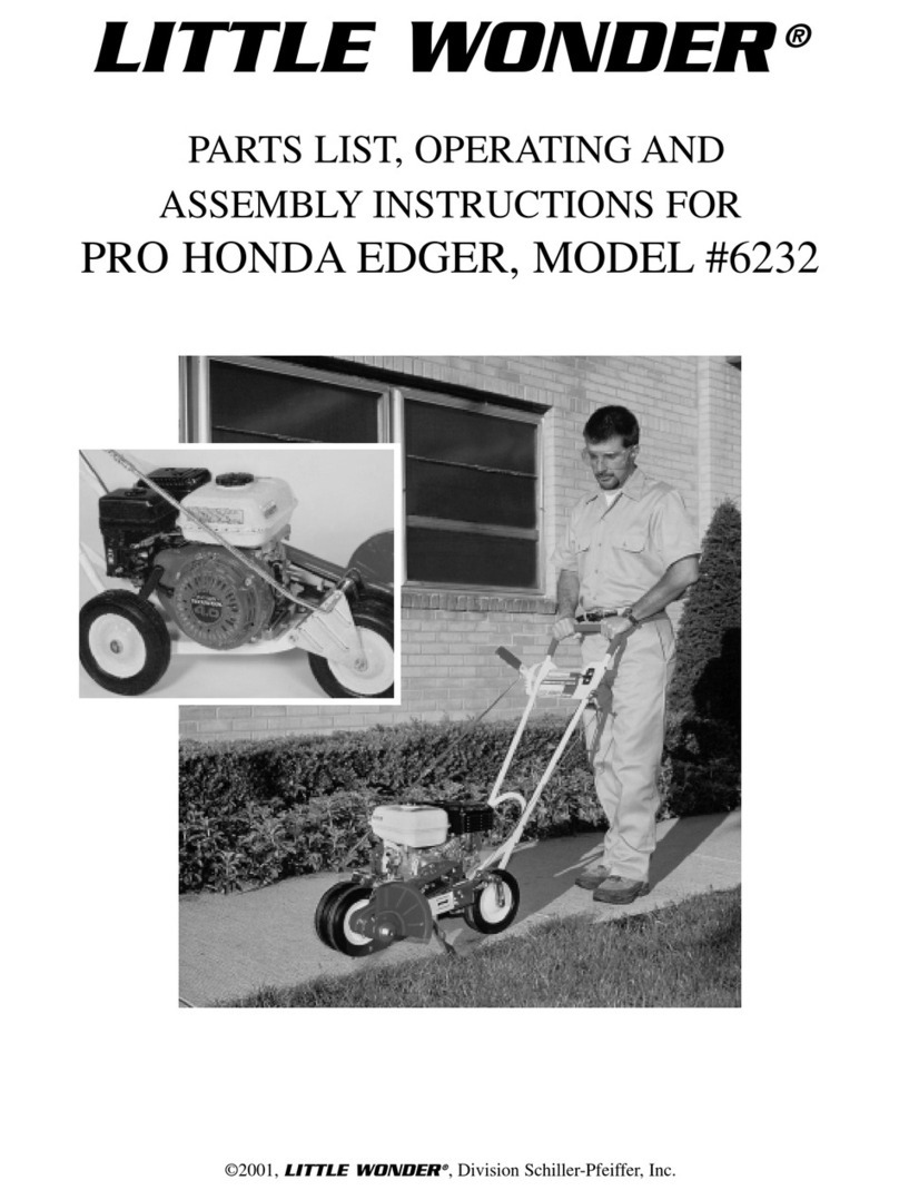
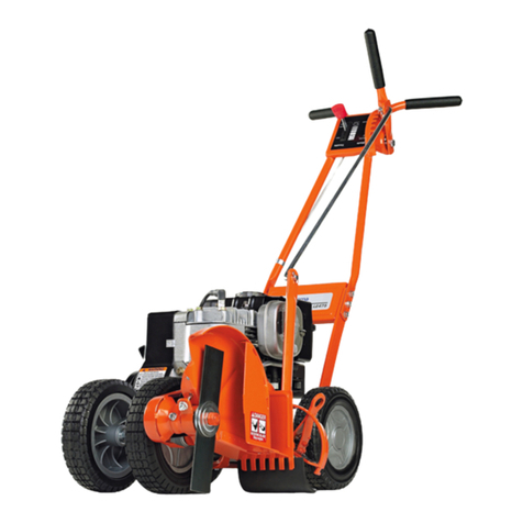
Little Wonder PRO EDGER 6232-00-59 User manual

Set-Up and Parts Manual for
LITTLE WONDER Pro Edger
MAN 4168762
Rev A. 01-2013
Original Language Instructions
LITTLE WONDER
PRO EDGER
6232-00-59
PARTS / SET-UP MANUAL

CALIFORNIA
Proposition 65 Warning
Diesel engine exhaust and some
of its constituents are known to the
State of California to cause cancer,
birth defects and other reproductive
harm.
WARNING
The engine exhaust from this product
containschemicalsknowntotheState
of California to cause cancer, birth
defects or other reproductive harm.
CALIFORNIA
Proposition 65 Warning
Battery posts, terminals, wiring
insulation, and related accessories
contain lead and lead compounds,
chemicals known to the State of
California to cause cancer and birth
defects or other reproductive harm.
WASH HANDS AFTER HANDLING.

3
PRO EDGER
IMPORTANT MESSAGE
ThankyouforpurchasingthisLittleWonderproduct. Youhavepurchasedaworldclassproduct,oneofthebestdesignedandbuiltanywhere.
This machine comes with an Operation and Safety Manual, Parts and Service Manual, and Engine Manual. The useful life and good service
you receive from this machine depends to a large extent on how well you read and understand these manuals. Treat your machine properly,
lubricate and adjust it as instructed, and it will give you many years of reliable service.
Your safe use of this Little Wonder product is one of our prime design objectives. Many safety features are built in, but we also rely on your
good sense and care to achieve accident-free operation. For best protection, study the manuals thoroughly. Learn the proper operation of
all controls. Observe all safety precautions. Follow all instructions and warnings completely. Do not remove or defeat any safety features.
Make sure those who operate this machine are as well informed and careful in its use as you are.
See a Little Wonder dealer for any service or parts needed. Little Wonder service ensures that you continue to receive the best results
possible from Little Wonder products. You can trust Little Wonder replacement parts because they are manufactured with the same high
precision and quality as the original parts.
Little Wonder designs and builds its equipment to serve many years in a safe and productive manner. For longest life, use this machine only
as directed in the manuals, keep it in good repair and follow safety warnings and instructions. You’ll always be glad you did.
LITTLE WONDER
SCHILLER GROUNDS CARE, INC.
1028 STREET ROAD, P.O. BOX 38
SOUTHAMPTON, PA 18966
01-2013
TABLE OF CONTENTS FIGURES PAGE
SAFETY.........................................................................................................................................................4-6
SET UP INSTRUCTIONS.................................................................................................................................7
CONTROLS......................................................................................................................................................8
PARTS SECTION.............................................................................................................................................9
HANDLE ASSY....................................................FIGURE 1...................................................................10, 11
BLADE / DRIVE ASSY........................................FIGURE 2...................................................................12, 13
MAIN FRAME ASSY............................................FIGURE 3...................................................................14, 15
WARRANTY............................................................................................................................... BACK COVER
This Manual is part of the machine. Suppliers of both new and second-hand machines
must make sure that this manual is provided with the machine.
See manual 4168761 for Operator’s Manual

4
PRO EDGER
MODEL NUMBER: This number appears on
sales literature, technical manuals and price lists.
SERIAL NUMBER: This number appears only
on your unit. It contains the model number fol-
lowed consecutively by the serial number. Use
this number when ordering parts or seeking war-
ranty information.
SAFETY
NOTICE !!!
Unauthorized modications may present extreme
safety hazards to operators and bystanders and
could also result in product damage.
Schiller Grounds Care, Inc. strongly warns against,
rejects and disclaims any modications, add-on
accessories or product alterations that are not
designed,developed,testedandapprovedbySchiller
Grounds Care, Inc. Engineering Department. Any
Schiller Grounds Care, Inc. product that is altered,
modied or changed in any manner not specically
authorized after original manufacture-including the
additionof“after-market”accessoriesorcomponent
parts not specically approved by Schiller Grounds
Care, Inc. will result in the Schiller Grounds Care,
Inc. Warranty being voided.
Any and all liability for personal injury and/or
property damage caused by any unauthorized
modications, add-on accessories or products not
approved by Schiller Grounds Care, Inc. will be
considered the responsibility of the individual(s) or
company designing and/or making such changes.
Schiller Grounds Care, Inc. will vigorously pursue
full indemnification and costs from any party
responsibleforsuchunauthorizedpost-manufacture
modications and/or accessories should personal
injury and/or property damage result.
This symbol means:
ATTENTION!
BECOME ALERT!
Your safety and the safety of others is involved.
Signal word denitions:
The signal words below are used to identify levels
ofhazard seriousness. These wordsappear in this
manualandonthesafetylabelsattachedtoSchiller
Grounds Care, Inc. machines. For your safety and
thesafetyofothers,readandfollow theinformation
given with these signal words and/or the symbol
shown above.
DANGER indicates an imminently hazardous
situationwhich, if notavoided, WILL result in death
or serious injury.
WARNING indicates a potentially hazardous
situation which, if not avoided, COULD result in
death or serious injury.
CAUTIONindicatesapotentiallyhazardoussituation
which,ifnotavoided,MAY resultinminorormoderate
injury. It may also be used to alert against unsafe
practices or property damage.
CAUTION used without the safety alert symbol
indicates a potentially hazardous situation which, if
not avoided, MAY result in property damage.

5
PRO EDGER
Fuel
- Gasoline (petrol) and die-
sel fuels are ammable;
gasoline (petrol) vapors
are explosive. Use extra
care when handling.
- Store only in containers
specically designed for
fuel.
MAINTENANCE SAFETY
IN GENERAL
• Maintain machine according to manufacturer’s
schedule and instructions for maximum safety and
best results.
• Park machine on level ground.
• Never allow untrained personnel to service
machine.
• Guards should only be removed by a qualied
technician for maintenance or service. Replace
when work is completed.
• Adjust or repair only after the engine has been
stopped and the blade has stopped moving.
• Disconnect spark plug wire before doing any
maintenance.
• Replace parts if worn, damaged or faulty. For best
results, always replace with parts recommended by
the manufacturer.
• Do not dismantle the machine without releasing or
restraining forces which may cause parts to move
suddenly.
• Provide adequate support, e.g. jack stands for lifted
machine or parts if working beneath.
• Do not put hands or feet near or under rotating
parts.
• Clean up spilled oil or fuel thoroughly.
• Replace faulty mufers.
• To reduce re hazards, keep the engine, mufer,
and fuel storage area free of grass, leaves, debris
buildup or grease.
• Never attempt to make adjustments while the
engine is running except for repairs or adjustments
as specically noted, such as for carburetor
adjustment, where the engine must be running.
Keep hands and feet clear of moving parts in these
circumstances.
WARNING
Blades
Do not straighten or weld blades. Replace dam-
aged blades.
- When refueling or checking fuel level:
- Stop the engine and allow to cool;
- Do not smoke;
- Refuel outdoors only;
- Use a funnel;
- Do not overll;
- If fuel is spilled, do not attempt to start the
engine until the spill is cleaned up and vapors
have cleared.
- Replace caps on fuel containers and tanks
securely.
Sparks from static electricity can start res or
cause explosions. Flowing fuel can generate static
electricity. To prevent static electricity sparks:
- Keep containers electrically grounded. Do not ll
containers in a vehicle or on a truck or trailer bed
with a plastic liner. Fill containers on the ground
away from the vehicle.
- When practical, remove petrol (gasoline)
powered equipment from the truck or trailer
and refuel it on the ground. If equipment must
be refueled on the truck or trailer, refuel from
a portable container rather than a dispenser
nozzle.
- Keep the dispenser nozzle in contact with the rim
of the fuel tank or container opening until fueling
is complete. Do not use a nozzle lock-open
device.
- If fuel is spilled on clothing change it immediately.
STORAGE SAFETY
- Stop the engine and allow to cool before storing.
- Drain the fuel tank outdoors only.
- Store fuel in an approved container in a cool, dry
place.
- Keep the machine and fuel containers in a locked
storage place to prevent tampering and to keep
children from playing with them.
- Do not store the machine or fuel container near an
open ame, spark, or appliance, such as a water
heater, or a pilot light.
- Keep gasoline (petrol) storage area free of grass,
leaves and excessive grease to reduce re haz-
ard.
- Clean grass and debris from cutting units, drives,
mufers and engine to help prevent res.
SAFETY

6
PRO EDGER
SAFETY
WARNING LABELS
Warning labels are an important part of the safety system incorporated in this machine.
Replace labels if damaged or illegible.
LITTLE
WONDER®
EDGER
PN 4168356
Key #A P/N 4168356 4168759
Key #B P/N 4168759
Key #C P/N 4168758
4168758

7
PRO EDGER
ASSEMBLY INSTRUCTIONS
Your Little Wonder Pro Edger requires a minimal amount
of assembly prior to use. Use Figures 1 & 3 in parts sec-
tion for assembly.
1. Remove two nuts & bolts (P/N 472 & 144-1), holding
handle supports (P/N 267 & 266) to lower handle (P/N
141-2).
2. Align upper handle (P/N 142-2) with lower handle (P/N
141-2 and replace the two nuts and bolts that were
removed in step one.
3. Use two bolts & nuts (P/N 472 & 144-1) in the upper
holes of the handles - now tighten all four bolts.
4. Use a #10-32 x 1 1/4 screw and lock nut (P/N 208 &
973) to connect the upper adjusting rod (P/N 155) to
the lower adjusting rod (P/N 4163572).
5. Remove cotter pin and washer (P/N 156 & 163) from
belt slackener lever (P/N 167-2) and place elongated
loop of the draw bar (P/N 198) onto the belt slackener
lever. Place washer back on and install cotter pin
bending the legs once it is in place.
6. Remove the cotter pin (P/N 156) from the clevis pin
(P/N 170) and slide the clevis pin out of its hole. Place
the round hole of the draw bar (P/N 198) between the
two holes of the link belt slackener (P/N 169) and slide
clevis pin back in place.
7. Replace cotter pin and bend the legs.
8. Rotate the mud flap (P/N 209) out from under the
machine so that it is as far forward as possible without
touching the brush while the paving cleaner is in its
lowest position and the rubber flap is bent forward.
Tighten from underneath.
BLADE INSTALLATION
Use Figure 2 in parts section for assembly.
1. Place one blade washer (P/N 128) on the cutter head
shaft, and up against the bearing (P/N 124). make
sure the side with the step is against the bearing and
the flat side of the washer is facing away from the
bearing.
2. Slide the Blade (P/N 129) onto the cutter head shaft.
3. Place remaining blade washer (P/N 128) on the cut-
ter head shaft. Make sure the flat side is against the
blade and the side with the step is facing away from
the blade.
4. Attach a flange nut (P/N 130) onto the shaft and
tighten..
5. Position the enclosed Blade Guard (P/N 129B-
W.17) over the blade.
6. Align the holes in the blade guard with those on the
cutter head. Secure with two hex head screws (P/N
129C), lock washers (P/N 129D), and flat washers
(P/N 163).
SET-UP INSTRUCTIONS
THROTTLE INSTALLATION
Use Figure 1 in parts section for assembly.
1. Remove the air filter cover from the engine.
2. Use a 10mm socket to loosen the throttle lever
pivot nut.
3. Move the remote throttle lever all the way to slow
(turtle) position. Move it 1/16” - 1/8” back towards
the fast (rabbit) position.
4. Move the engine throttle lever to the slow position
(push throttle lever to the front of the edger).
5. Remove the throttle cable retaining clamp and
screw from the engine.
6. Insert the end of the throttle cable into the hole on
the engine throttle lever.
7. Place the cable-retaining clamp over the cable,
insert the screw in and pull back and tighten.
8. Replace the air filter cover.
9. The remote throttle lever should move from slow to
fast and be approximately centered in its slot.
10. If the throttle feels tight, loosen the engine throttle
lever pivot nut.
11. If the throttle does not stay where it is placed,
tighten the remote throttle lever pivot nut (P/N 410).

8
PRO EDGER
CONTROLS
CONTROLS
BLADE HEIGHT ADJUSTMENT LEVER (A)
Rotate the lever away from the operator to raise the
blade.
Rotate the lever toward the operator to lower the
blade.
THROTTLE CONTROL (B)
Controls engine speed and controls speed of the
blade.
Pushing the lever forward makes the engine speed
go faster, while pulling the lever back slows down
the speed of the engine
BELT SLACKENER LEVER (C)
Rotate the lever towards the operator to disengage
the blade.
Rotate the lever away from the operator to engage
the blade.
ENGINE START/STOP SWITCH (D)
Move to the “OFF” position to stop the engine.
Move to the “ON” position before starting the
engine.
FUEL VALVE (F)
Move to the “OFF” position to shut off the fuel
whenever transporting the machine by trailer or
truck or during storage. Move to the “ON” position
before starting the engine.
CHOKE (G)
Move to the “CHOKE” position to apply the choke.
Move to the “RUN” position to remove the choke.

9
PRO EDGER
PARTS
SECTION

10
PRO EDGER
HANDLE ASSEMBLY
FIGURE 1
2
11
7
8
18
9
10
12
113
14
21
20
15
16
19
1
111
24
1
23
22
3
5
11
17
4
25
1
2
6

PRO EDGER
1111
ITEM PART NO. DESCRIPTION QTY
HANDLE ASSEMBLY
FIGURE 1
1 144-1 HEX HD CAP SCREW 1/4-20X1 1/4 12
2 163 WASHER - 3/8 ID 3
3 146B THROTTLE CLIP 1
4 156 COTTER PIN 2
5 167A SPEED NUT 1
6 198 DRAW ROD 1
7 271 THROTTLE ADJUST ASSEMBLY 1
8 410 HEX HEAD CAP SCREW 1/4-20 X 5/8 1
9 8-18 GRIP RING 1
10 227 GRIP - LEVER 1
11 472 LOCK NUT 1/4-20 9
12 228 LEVER 1
13 980 HEX HEAD CAP SCREW 3/8-16 X 2 1
14 155 ADJUSTING ROD UPPER 1
15 218 SPRING 1
16 102B HEX NUT 3/8-16 2
17 226 HANDLE BRACE 1
18 236 GRIP - HANDLE 2
19 142-2 HANDLE UPPER 1
20 973 LOCK NUT #10-32 1
21 208 HEXHEAD CAPSCREW #10-32 X3/4 1
22 167-2 BELT SLACKENER LEVER 1
23 165A GRIP 1
24 141-2 HANDLE-LOWER 1
25 219 BRACKET 1
26* 4168356 BRACE LABEL 1
*NOT ILLUSTRATED

PRO EDGER
12
22
12
23
8
15
16
6
3
5
4
2
21
10
314 7
13
26
9
18
28 27
11
20 24
19
22
31
19
36
20
34
4
35
29
33
30 32
37
25
17
6
43
44
45
42 42
42
41
40
46
1
BLADE / DRIVE ASSEMBLY
FIGURE 2

13
PRO EDGER
ITEM PART NO. DESCRIPTION QTY
1 162B HEX HEAD SCREW 1/4-20 X 1/2 2
2 118 SET SCREW 5/16-18 X 3/8 4
3 124 BEARING 2
4 129D LOCK WASHER 5/16 5
5 131A CUTTER HEAD SHAFT 1
6 128 BLADE WASHER 2
7 121 WOODRUFF KEY #606 1
8 132 TENSION PIN 1/4 X 1 1/4 1
9 100-C DECK BRACKET 1
10 220 PULLEY CUTTER HEAD 1
11 472 LOCK NUT 1/4-20 7
12 163 WASHER - 3/8 ID 2
13 134 SPRING 1
14 181 CUTTER BLADE SHAFT 1
15 126 CUTTER HEAD 1
16 130 NUT 1/2-20 1
17 129 BLADE 1
18 138 KEY HEAD SHAFT 1
19 192 GUIDE PLATE 1
20 114B FLANGE NUT 5/16-18 10
21 122 RETAINING RING 1
22 129C HEX HEAD SCREW 5/16-18 X 3/4 8
23 129B-W.17 BLADE GUARD 1
24 191 GUIDE BRACKET 1
25 264 MUFFLER, EXHAUST DFLCTOR 1
26 177 V BELT 2
27 195P BELT GUARD 1
28 140 HEX HEAD SCREW 1/4 - 20 X 3/8 2
29 196 HEX HEAD SCREW 5/16-24 X 1 1/4 1
30 197 JAM NUT 5/16-24 1
31 251 PULLEY - ENGINE 1
32 262 ENGINE-4HP HONDA 1
33 212 BRACKET 1
34 213 HEX HEAD SCREW 5/16 - 24 X 3/4 3
35 253 ADAPTER PLATE 1
36 117 KEY, PULLEY - 3/16” SQUARE 1
37 265 M4X8 PHILLIPS HEAD SLFTAPG 2
38* 4168758 WARNING LABEL BLADE 1
39* 4168759 WARNING LABEL 1
40 910156 MUFFLER PLATE HONDA 1
41 910158 STANDOFF 5/8 2
42 910159 STANDOFF 5/16 4
43 910531 NUT WIZ FLANGE 10-24 3
44 910532 SCREW SELF TAPPING M5 X 16 1
45 910533 SCREW SELF TAPPING M5 X 25 2
46 4164805.7 MUFFLER GUARD-4HP HONDA 1
*NOT ILLUSTRATED
BLADE / DRIVE ASSEMBLY
FIGURE 2

14
PRO EDGER
MAIN FRAME ASSEMBLY
FIGURE 3
17
3
24
28
20
15
18
28
16
19
16
11
2
23
51
26
12
6
29 6
9
22
8
2
30
14 6
27
10
725
4
21
28 13
27

15
PRO EDGER
ITEM PART NO. DESCRIPTION QTY
MAIN FRAME ASSEMBLY
FIGURE 3
1 114B FLANGE NUT 5/16-18 10
2 129C HEX HD SCRW 5/16-18 X 3/4 8
3 163 WASHER - 3/8 ID 5
4 4163308 FORMED ROD .19 X 2.28 1
5 209 MUD FLAP 1
6 176 WASHER 1/2 ID 8
7 156 COTTER PIN 2
8 267 HANDLE SUPPORT - RH 2
9 103 RETAINING RING 2
10 169 LINK BELT SLACKENER 1
11 141-2 HANDLE-LOWER 1
12 184 AXLE 1
13 185 CLEVIS PIN 1
14 4163306 BOLT, EYE END 1/4-20X1.40 1
15 102B HEX NUT 3/8-16 2
16 113 HEXHEADSCREW 5/16-18X11/2 4
17 194 HEX HEAD SCREW 3/8-16X5 1/2 1
18 102C SLEEVE 2
19 100D DECK BRACKET SUPPORT 1
20 4163572 ADJUSTING ROD LOWER 1
21 171 CLEVIS PIN 1
22 100 DECK 1
23 193 FRONT WHEEL BRACKET 1
24 108 WHEEL HOUSING 2
25 170 CLEVIS PIN 1
26 266 HANDLE SUPPORT - LH 1
27 106 WHEEL 3
28 8-18 GRIP RING 3
29 107 OFFSET WHEEL 1
30 175B NUT, 1/4-20 1
* NOT ILLUSTRATED

©2012 Schiller Grounds Care, Inc.All Rights Reserved.
LITTLE WONDER®
SCHILLER GROUNDS CARE, INC.
1028 STREET ROAD, P.O. BOX 38
SOUTHAMPTON, PA 18966
PHONE 877-596-6337 • FAX 215-357-8045
www.littlewonder.com
All LITTLE WONDER PRO EDGERS are warranted against defects in material and workmanship for a period of
one (1) year from the date of purchase, under the following terms and conditions.
LITTLE WONDER will repair or replace, at its option, any part or parts of the product found to be defective in ma-
terial or workmanship during the warranty period. Warranty repairs and replacements will be made without charge
for parts or labor. All parts replaced under warranty will be considered as part of the original product, and any
warranty on the replaced parts will expire coincident with the original product warranty. If you think your LITTLE
WONDER PRO EDGER is defective in material or workmanship, you must return it to a registered dealer with a
valid sales receipt or to our factory at 1028 Street Rd., Southampton, PA 18966. Transportation charges to ship
your product to us or a registered dealer must be borne by you.
Engines for all gasoline powered products are warranted separately by the engine manufacturer. Therefore, there
are no warranties made, expressed or implied, for engines for gasoline powered products by Little Wonder.
LITTLE WONDER assumes no responsibility in the event that the product was not assembled or used in compli-
ance with any assembly, care, safety or operating instructions contained in the Owner’s Manual or information
accompanying the product. This limited warranty does not cover damages or defects due to normal wear and
tear, lack of reasonable and proper maintenance, failure to follow operating instructions or Owner’s Manual,
misuse, lack of proper storage or accidents, nor does it cover routine maintenance parts and service. This limited
warranty does not cover any defects due to repairs or alterations made to the product made by anyone other than
LITTLE WONDER or its registered dealers.
You must maintain your LITTLE WONDER PRO EDGER by following the maintenance procedures described
in the owner’s manual. Such routine maintenance, whether performed by you or a registered dealer, is at your
expense.
LITTLE WONDER MAKES NO EXPRESS OR IMPLIED WARRANTIES REPRESENTATIONS OR PROMISES
EXCEPT THOSE CONTAINED HEREIN. THEREARE NO OTHER WARRANTIES, INCLUDING WARRANTIES
OF MERCHANTABILITYAND FITNESS FOR A PARTICULAR PURPOSE. ALL WARRANTIES OTHER THAN
THE EXPRESS WARRANTY SET FORTHABOVE ARE SPECIFICALLY DISCLAIMED. THE DURATION OF ANY
IMPLIED WARRANTY, INCLUDING MERCHANTABILITY AND FITNESS FOR A PARTICULAR PURPOSE, IS
LIMITED TO THE DURATION OF THIS WRITTEN LIMITED WARRANTY. LITTLE WONDER DISCLAIMS ALL
LIABILITY FOR INDIRECT, INCIDENTALAND/OR CONSEQUENTIAL DAMAGES IN CONNECTION WITH THE
USE OF THE LITTLE WONDER PRO EDGER PRODUCTS COVERED BY THIS WARRANTY. SOME STATES
DO NOTALLOW LIMITATIONS ON HOW LONG AN IMPLIED WARRANTY LASTSAND/OR DO NOTALLOW
THE EXCLUSION OR LIMITATION OF INCIDENTAL OR CONSEQUENTIAL DAMAGES, SO THAT ABOVE
LIMITATIONS AND EXCLUSIONS MAY NOTAPPLY TO YOU. THIS WARRANTY GIVES YOU SPECIFIC LEGAL
RIGHTS, AND YOU MAYALSO HAVE OTHER RIGHTS WHICH VARY FROM STATE TO STATE.
©2013 Schiller Grounds Care, Inc.All Rights Reserved.
1 YEAR LIMITED SERVICE AND
WARRANTY POLICY
FOR LITTLE WONDER PRO EDGER
LITTLE WONDER®
SCHILLER GROUNDS CARE, INC.
1028 STREET ROAD, P.O. BOX 38
SOUTHAMPTON, PA 18966
PHONE 877-596-6337 • FAX 215-357-8045
www.littlewonder.com
Table of contents
Other Little Wonder Edger manuals

Little Wonder
Little Wonder 6031 Datasheet

Little Wonder
Little Wonder 6232 Product guide

Little Wonder
Little Wonder PRO HONDA 6232 Product guide

Little Wonder
Little Wonder Xtra Installation instructions

Little Wonder
Little Wonder BedShaper Original instruction manual

Little Wonder
Little Wonder BedShaper 900 User manual