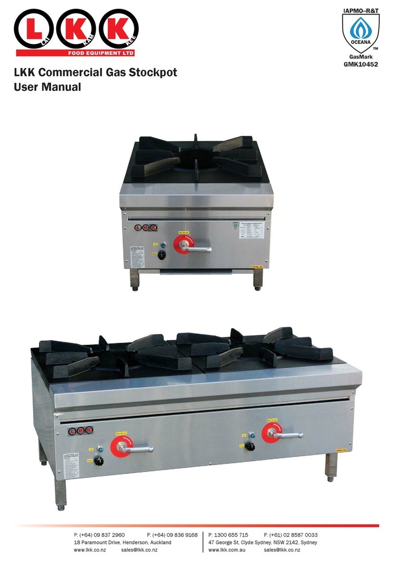
LKK Wok Series User guide

LKK Wok Series:
User Manual &
Servicing Instructions
18 Paramount Drive, Henderson, Auckland, New Zealand
All drawings in this book remains the property of LKK Food Equipment Ltd - LKK reserves the right to change product specifications without notice - 2012 December

WOKSERIESSILOCNINSTRUCTIONS
Step1
Step2
Step3
Note:PicturesshownforassemblyisdemonstratedwithLKK-1B
Clean the join area where the splash back connects to the unit body
Apply Silocon to the sides and the back of the lip
Install splash back and screw in the screws supplied before wiping silocon excess o.

P
PP
Pa
aa
ag
gg
ge
ee
e
1
11
1
OPERATION AND INSTALLATION INSTRUCTION
WOK TABLE: LKK-D SERIES (Duckbill burner)
LKK-C SERIES (Chimney Burner)
OPERATION INSTRUCTIONS:
These instructions should be read carefully prior to operating your Wok table
LIGHTING UP OF APPLIANCE: (AW20 Valve)
1Ensure the gas valve lever is in the horizontal position as indicated on the panel "OFF"
2. Turn pilot control knob to "ON" position (HIGH)
3. Depress round D-3 button and light pilot, hold button in for at least 20 sec. (on new
installations you may have to hold the button longer to allow air in pipes to purge out for several
minutes)
4. Release button when pilot light is established
5. Turn the main burner on by moving lever to “ON” position. (If pilot fails to remain alight when
main burner ignites turn main burner lever to the OFF position, wait 30 seconds and repeat step 3
(check aeration for correct flame setting)
6. To shut down appliance, turn pilot control knob to off position
LIGHTING UP OF APPLIANCE: (A63C Valve)
1Ensure the gas valve lever is in the horizontal position as indicated on the panel "OFF"
2. Depress the main gas valve and light the pilot. Hold lever in for at least 20 sec. (on new
installations you may have to hold the button longer to allow air in pipes to purge out for several
minutes)
3. Release lever when pilot light is established
4. Turn the main burner on by moving lever to “ON” position. (If pilot fails to remain alight when
main burner ignites turn main burner lever to the OFF position, wait 30 seconds and repeat step 2
(check aeration for correct flame setting)
5. To shut down appliance, push the lever in half way and turn handle clockwise approximately
30 degrees. Once off return the lever back to the off position.
INSTALLATION: (By authorised personnel only)
Gas point entry is 520mm above floor and located on the right hand side of the appliance at the rear
of the unit. A regulator is supplied with the unit for each burner
Bromic/Oara 980L AGA#5862 (Natural Gas)
Bromic/Oara 986L AGA#5862 (L.P.G)
Maxitrol, RV48 AGA#3088 (Natural Gas)
Maxitrol, RV48 AGA#3088 (L.P.G)
The installer must fit an isolating gas valve to the appliance for ease of servicing.
Check alignment of burner injector to pilot flame to insure burner ignition prior to use.
The appliance installation must comply with the installation requirements of AG 601, AS 5601,
Australian Standard, “Gas Installations” any local Authority regulation and the Manufacturer’s
installation instructions.
Warning: Please do not install LKK woks in marine environment. Some examples include on a boat
or outdoor in the sea breeze. Doing so will result in unnecessary rust.
*Please remove all packaging prior to installation*’
CLEARANCES AND PROTECTION AROUND COMMERCAIL CATERING EQUIPMENT
The clearance to combustible surfaces from commercial catering equipment shall comply with the
requirements of the appliance manufacturer
- From a cooking surface area having an open flame and no means of preventing cooking vessels
from overhanging the edge of the appliance 250mm
- From the side of an open flame appliance where the combustible surface is at least 100mm
below a cooking surface area
- From an appliance flue way or rear of an appliance with a ‘splash back’ 50mm

P
PP
Pa
aa
ag
gg
ge
ee
e
2
22
2
- From the rear or side of an appliance which is not an open cooking flame appliance 50mm
* Do not spray aerosols in the vicinity of this appliance while it is in operation *
* Do not store flammable materials on or near this appliance *
Notes:
1 The cooking surface area is defined as being that part of the appliance where cooking
normally takes place and does not include those parts of the appliance containing control
knobs.
2 If a timber preparation table is adjacent to a commercial range, and the table has a
combustible surface that is 100mm below the hob, then 50mm clearance is required from the
range. Any combustible surface higher than that would need to have at least 250mm
clearance, or be protected.
3 These clearances do not apply where an adjacent surface is of a non-combustible material or
is combustible but is protected with fire resistant material in accordance with Appendix C. The
fire resistant material may be covered by ceramic tiles or stainless steel to meet local Health
Authority requirements.
4 Care should be taken where a combustible surface is covered by a non-combustible material.
For example, covering a combustible surface with stainless steel will not prevent heat
transfer, and in some circumstance a hazardous situation could arise.
COMMERCIAL CATERING EQUIPMENT ON A COMBUSTIBLE SURFACE
Where commercial catering equipment is installed on a combustible surface the surface shall be
protected by fire resistant material. The protection is to extend at least 50mm beyond the perimeter of
the appliance and is to be made impervious to cooking fats.
NOTE: This requirement does not apply where the lowest burner on the appliance is over 200mm
above the mounting surface, and a heat shield below the burner is incorporated in the design of the
appliance.
Please ensure the appliance is commissioned to the Manufacturers settings designated on the
appliance data plate.
Every model has a 20mm ¾ BSP galvanised pipe threaded to individual holes
Water connections are on the right hand side of unit and are 1/2 –13mm compression x 420mm
above floor to stop tap.
Waste water/drainage located at front with 50mm S/S trap and 1 a stainless steel rubbish catcher
(double filtration)
Before leaving installation check all gas and water fittings for leaks, and instruct the operator in the
lighting procedure and use of appliance.
If unit fails to operate contact local distributor or call manufacturer.
Any of the following are deemed to be abnormal:
1) Burners burning with a yellow soft flame
2) Sooting of pots, pans and woks
3) Unusual odours being emitted when appliance is operating
Please contact your service agent if any of the above is present

P
PP
Pa
aa
ag
gg
ge
ee
e
3
33
3
LKK WOK BENCH SERVICING INSTRUCTION
WOK TABLE: LKK-D SERIES (Duckbill burner)
LKK-C SERIES (Chimney Burner)
OPERATION INSTRUCTIONS:
These instructions should be read carefully prior to operating your Wok table
- Servicing an LKK appliance should only be carried out by an authorised LKK gas technician or
certified plumber.
- Any evidence of tamper will be void of warranty and not covered.
Step 1:
Check and assess the problem.
- Try to ignite unit and turn on as per usual, if it does not ignite follow accordingly.
- Check the correct gas regulator is installed to the right gas supplied.
- Check unit is supplied to suit the desired gas type (NG or ULPG)
- If unit is showing any signs of the below problems, follow steps accordingly
Problem 1: Pilot light won’t stay lit.
a) If flame is too small and not contacting thermocouple, use flat tip screw driver and locate a
screw under pilot light. Turn screw anti clockwise to increase flame size
b) If flame is contacting thermocouple but won’t stay lit after releasing D3 safety valve.
Thermocouple must be changed. Part no. SIT0200009
c) If pilot is broken, pilot must be changed.
Problem 2: If wok is working but the burner injectors are blocked (Not covered under
warranty)
This situation is not covered under warranty, blockage is normally caused when food scraps
drop into the burners while cooking. A cleaning fee/ unblocking fee will apply
LKK Injector unblocking tools are available for purchase (sold separately)
Available to suite Duckbill burner or Chimney burners
Problem 3: Leaky Splash back
An LKK Wok unit recommends installing the splashing back with silicon prior to install.
If unit is leaking and silicon was not applied during install, labour charges is not chargeable to
LKK or applies under warranty
See instructions on how to apply silicon
Problem 4: Customer does not like Duckbill burner
All LKK units come standard with Duckbill burners installed by default unless arranged.
To change from Duckbill to Chimney burner, please see burner conversation instructions

P
PP
Pa
aa
ag
gg
ge
ee
e
4
44
4
MAINTENANCE
Should be carried out by an authorized technician.
Contact LKK Food Equipment for the nearest technician in your area.
It is recommended that this appliance be serviced every 6 months by authorised service technician
All normal care should be taken in up keep of gas equipment, make sure burners and gas cocks are
cleaned after heavy daily use to prevent any major damage avoid spillage onto burners or gas cocks,
if not sure call above number for advice.
All spare parts available from manufacturer
LKK Food Equipment Ltd (NZ)
Freephone: 0800 524 526 Fax: 09 836 9168
18 Paramount Drive, Henderson, Auckland, New Zealand
www.lkk.co.nz sales@lkk.co.nz
LKK Food Equipment Aust Pty Ltd (Australia)
Freephone: 1300 655 715 Fax: 02 8587 0033
47 George St, Clyde, Sydney NSW 2128, Australia
www.lkk.net.au sales@lkk.co.nz
Table of contents
Other LKK Commercial Food Equipment manuals