LMI 200-S Quick guide

101 N. Alloy Dr.
Fenton, MI 48430
Ph (810) 714-5811
Fax (810) 714-5711
CustomerService@lmicorporation.com
Research, Development and Manufacturing of Precision Measuring Systems
Form: CA 033 September 21,
2004 R:\Quality\Calibration Instructions\CA 033.doc Rev. A Page 1 of 7
Configuration and Mastering Instruction for the
LMI 200-S or LMI 200-SB to the LMI 440 or ASI DataMyte 501
This process will outline:
Section Pages
I. Configuration of the LMI 440 or ASI DataMyte 501 2-4
II. Mastering the LMI 200-S or 200-SB 5-6
III. How to verify the mastering of the LMI 200-S or 200-SB 7
Required Equipment:
1LMI 440 or ASI DataMyte 501
2LMI 200-S or 200-SB transducer
3LMI 210 master block
4LMI 6009 4
p
in
–
4
p
in cable
1
4
2
3
E-mail support
techsupport@lmicorporation.com LMI Corporation Phone support
(810) 714-5811
Form: CA 033 September 21,
2004 R:\Quality\Calibration Instructions\CA 033.doc Rev. A Page 2 of 7
I. GAGE CONFIGURATION
Section I is a one time setup. After a successful gage configuration is finished there should be no
need to repeat section I. It is recommended to store a copy of the gage files onto a personal computer
or laptop. Consult the collector manual or if purchased the TranSend manual for further details.
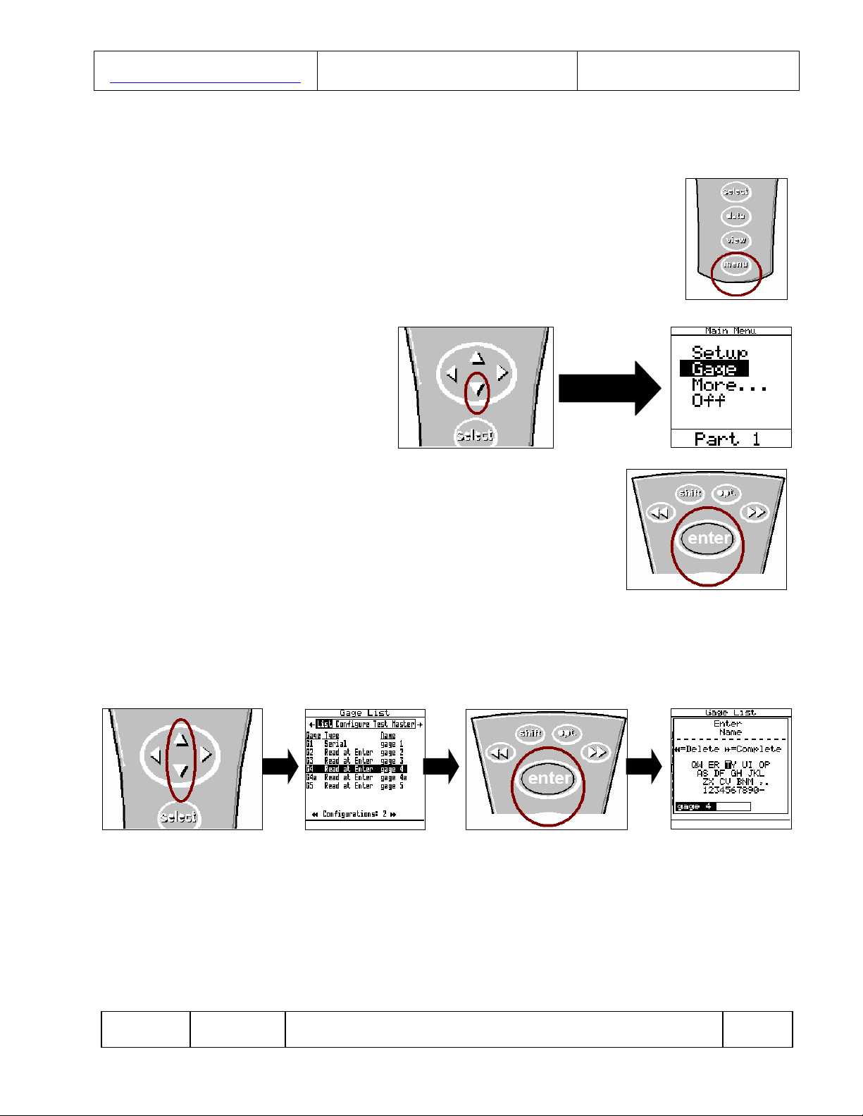
1. Press <menu> to turn on the collector.
2. Press 6to highlight “Gage”.
3. Press <enter>.
It is recommended to assign simple user name to the gage files such as; 200, probe, lmi probe, etc.
This will help to identify different setups.
4. To assign a gage file name press the ▲or ▼to highlight gage “G4”* in the “Gage List”, and
press <enter> on the collector. The alphanumeric screen will then appear.
*G4 and G5 can both read the 200 series probes. The only rule to follow is the gage file must match
the source code in part file, see collector manual for details. The balance of this instruction will be
based on G4. To use G5, perform the following steps using the G5 gage file.

E-mail support
techsupport@lmicorporation.com LMI Corporation Phone support
(810) 714-5811
Form: CA 033 September 21,
2004 R:\Quality\Calibration Instructions\CA 033.doc Rev. A Page 3 of 7
5. Use the ▲, ►, ◄, or ▼to highlight the desired character then press <enter>, repeat process
until the gage file name is spelled out then press ►► to accept the new name.
6. Press the ►to “Configure”. By default the screen should read as follows. This screen
determines how the collector will interpret the signal from the gage. Failure to set this screen
properly may cause undesired results. If no changes to the screen are required, configuration
is complete and press the <menu> key. If changes are required continue to step 7.
7. If changes in this screen are needed, press the ▲or ▼to highlight the different selections
then press <enter> to toggle through the choices of “Type”, “Master Type”, and “Zero Before
Read”.
8. To make changes to the “Scale” or “Zero Master” press ▲or ▼to highlight “Scale” or “Zero
Master” and press <enter>. This will bring up the numeric keypad. Key in the new value and
press ►► to accept.

E-mail support
techsupport@lmicorporation.com LMI Corporation Phone support
(810) 714-5811
Form: CA 033 September 21,
2004 R:\Quality\Calibration Instructions\CA 033.doc Rev. A Page 4 of 7
9. Press the <menu> key to return to the “Main Menu”. If any changes were made in the “Gage
Configuration” screen a save gage notification will appear. If the changes are intentional
highlight “Save to current gage” and press <enter>. If changes are not intended, highlight
“Cancel” and press <enter> and reset “Configure Gages” per step 6.
Gage configuration is complete.

E-mail support
techsupport@lmicorporation.com LMI Corporation Phone support
(810) 714-5811
Form: CA 033 September 21,
2004 R:\Quality\Calibration Instructions\CA 033.doc Rev. A Page 5 of 7
II. MASTERING INSTRUCTIONS
LMI suggests that this process be performed at the start of every shift.
1. Connect the transducer to Gage Port 4 of the data collector. If G5
was selected in gage configuration use Gage Port 5.
2. Press <Menu> to turn on the DATAMYTE 501.
3. Press ▼to highlight “Gage”.
4. Press <enter>.
5From the gage list use the ▲or ▼keys on the data collector to choose gage file G4, and
press ◄on the collector.

E-mail support
techsupport@lmicorporation.com LMI Corporation Phone support
(810) 714-5811
Form: CA 033 September 21,
2004 R:\Quality\Calibration Instructions\CA 033.doc Rev. A Page 6 of 7
6“Master” will be highlighted in screen header and “G4” is identified as “Gage Port”. If G4 is
not the Gage Port press the ►► or ◄◄ until G4 appears.
7Place the transducer into the top or “Lo” step of LMI 210 Master Block. Verify “Master Lo”
is highlighted on the collector, press <enter>.
8Place the transducer into the bottom or “Hi” step of the LMI 210 Master Block. Verify
“Master Hi” is highlighted on the collector, press <enter>.
9Position the transducer into the calibration block’s center or Master. Verify “Master Zero” is
highlighted on the collector, press <enter>.
Calibration/ Mastering for the LMI 200 Series is now complete.
“Master”
highlighted
“G4” is the
Gage Port

E-mail support
techsupport@lmicorporation.com LMI Corporation Phone support
(810) 714-5811
Form: CA 033 September 21,
2004 R:\Quality\Calibration Instructions\CA 033.doc Rev. A Page 7 of 7
III. Verification of the Mastering
This process can be performed to verify the accuracy of the LMI 200-S or 200-SB after being
mastered.
1. Insert the 200 into the “Master”
position of the 210 block. The value
on screen needs to read 0.00 +/-
.03mm.
2. Insert the 200 into the “Lo” or top
step of the 210 block and observe the
value
3. Insert the 200 into the “Hi” or bottom
step of the 210 block and observe the
value.
4. Add the raw value of step 2 and 3 together, this example shows 4.49 + 5.51 = 10.00.The sum
of steps 2 and 3 needs to equal 10.00mm +/- .03.
If at any time the 0.00mm or 10.00mm span is not within +/- .03mm the 200-S or 200-SB needs
to be remastered.
Verification is now complete, press <menu> to exit.
This manual suits for next models
1
Table of contents
Other LMI Accessories manuals


