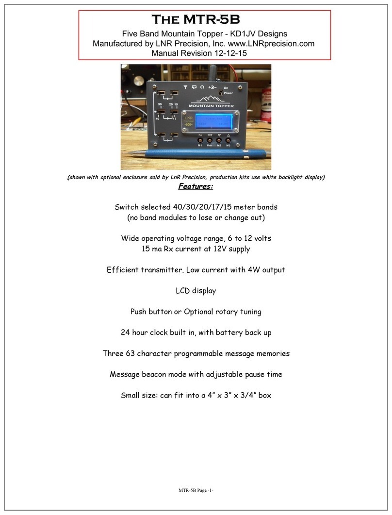
LNR Mountain Topper User manual

The Mountain Topper by Steve Weber (KD1JV)
(MTR)
www.LNRprecision.com
FULLY ASSEMBLED –Manufactured by LNR Precision, Inc.
A very small, very efficient three band QRP CW rig.
Specifications:
Three bands, 40M, 30M, 20M
Receiver:
MDS: ~0.2 uV
Small signal band width ~ 500 Hz
Audio output limited to ~ 1200 mv p-p
Headphone output, 16 ohms min recommended.
Transmitter:
2.5 watts @ 9 volt supply typical
Spurs -50 dBc or better
Size: 3.8” x 2.7” x 1” (LWH)
Weight: 4.4 ounces.
Power requirements:
6 volts minimum, 12 volts maximum.
Receive current:
~ 35 ma, no signal.
Transmit current:
~ 400 ma @ 9V, 20M
~ 550 ma @12V, 20M
(transmit current is slightly less on 40 and 30 meters)

Operation:
Basic operation:
Turning the rig on and off:
The slide switch to the right of the display turns the power on and off and is labeled with the international
on/off icons. The decimal point on the LED display is used as a power on indicator.
When the rig is powered up, it checks the position of the band select switch and loads the initial values
for that band. The display will flash a number to indicate the currently selected band (4, 3 or 2) and
annunciate that number in Morse.
The initial frequency operating frequency will be the QRP calling frequency for that band as shown in the
table below. It is possible to change these default frequencies to another more to your liking later if
you wish.
Band Display/Morse Initial frequency
________________________________
40 M 4 7.030 MHz
30 M 3 10.118 MHz
20 M 2 14.060 MHz
Band selection:
Three, DP3T switches are used to select one of the thee bands the rig has been built for.
Make sure all three switches are in the same position, i.e., left, center or right. It would be a good
idea to get into the habit of moving all the switches in sequence, like top to bottom.
The switch near the top edge of the case tells the processor which band is selected. When the position of
this switch is changed, the digit for the band selected will flash on the display.
When changing bands after initial power up, the last used frequency for that band will be loaded.
Volume control:
There is none! Instead, an automatic level control is built into the rig. This circuit limits the audio output
level to about 420 mV rms, which is about 10 mW into a 16 ohm load, typical for a pair of stereo ear buds
connected in parallel. With sensitive ear buds, this can actually produce too much volume if your hearing is
still good. In this case, an in line volume control can be added in series with your headphones.
Control switches:
Four push button switches control the
operation of the Mountain Topper.
All switches have multiple functions.
The primary function of each switch is
labeled in BLACK in the switch function
flow diagram shown to the right.
Secondary functions are enabled by a
short click (TAP) of either the <Fn>
switch or the <RIT> switch, followed by
clicking the switch for the desired
function. This allows often used
secondary functions to be quickly
accessed.
Additional functions are enabled by
holding the Fn or RIT switch closed for longer then 1 second.
You can right click on the image to print it out, then laminate it and tape to the bottom of the rig for
reference.
Frequency tuning:
The operating frequency of the rig is controlled by the TUNE UP and TUNE DOWN buttons. These are labeled on the

front panel with an up arrow and down arrow, respectively. “Clicking” the appropriate switch will increment or
decrement the current frequency by 50 Hz. Holding one of the tune switches closed for longer than one (1) second
will start an auto-tune mode. The frequency will now change in 100 Hz steps at a rate of about 10 steps a second
as long as the switch is held closed. Tuning will revert back to normal one step, 50 Hz tuning when the switch is
released. The 100 Hz / 10 steps a second tuning rate is a compromise between being able to scan the band at a
reasonable rate, while not being so fast its easy to miss weak signals.
Tuning limits:
The tuning range includes the entire band, though SSB reception is not possible since it will be received on the
wrong sideband. A double beep will sound when the band edges are reached and tuning will stop there, preventing
out of band transmission.
RIT:
The MTR has only RIT (Receive Incremental Tuning) and is limited to a tuning range of +/- 1500 Hz. When RIT mode
is enabled, the LED display is used to give indications of where you are tuned in respect to the transmit
frequency.
RIT is enabled by clicking and holding closed the <RIT> switch closed until the letter “R” is annunciated
in Morse by the side tone. There is a slight delay after closing the switch and the sending of the “R”,
as the RIT switch is also used to activate the transmission of keyer messages.
RIT is exited by clicking and holding closed the <RIT> switch until “E” is annunciated.
The display will blank and the original (Rx =Tx) operating frequency which was in use when RIT was
activated will be restored.
LED Display while in RIT mode:
While RIT is active, the display is used to show the approximate Rx
frequency delta relative to the Tx frequency, as illustrated by the
diagram.
A [0] is displayed when Rx = Tx frequency. A side tone beep is
also sounded when you tune back to the frequencies being
equal.
When you tune above or below the Tx frequency, but by less
then 250 Hz, the display will show [-]
When you tune beyond delta 250 Hz, LED segments above or below
the center [-] segment will light, changing in a clock wise direction for above the Tx frequency and
counter clock wise for below the Tx
Between 250 and 450 Hz, the upper left or bottom left segment will light. The upper segment for above the
Tx frequency and the bottom segment for below.
Between 500 and 950Hz, the top or bottom segment will light.
Above 1000 Hz, the upper right or bottom right segment will light.
AT 1500 Hz, the tuning limit, a beep will sound in the side tone.
Toggling between the RIT Rx frequency and the RX = Tx frequency:
Momentarily pushing the <Fn> button will toggle the receive frequency back to the transmit frequency to
check if the frequency is still clear or if someone is calling you there.
The top and center segments of the LED display will light, which is as close as we can get to making an
equal sign: [=].
While in Rx = Tx mode, you may transmit using the key or paddle, but no other functions will be
available.
Push the <Fn> button again to toggle back to the RIT frequency.
MENU:
The Fn switch is used to access, activate or escape from, the various functions and options available in the rig.
The Fn switch is sometimes used alone and sometimes in conjunction with the other switches to activate a
function. In all cases, how long the Fn switch is held closed will determine what function is to be activated.
Quick selections:
The DFE, Tune mode and battery voltage functions can be quickly accessed by using the <Fn> switch in conjunction
with one of the three other switches.
Click and release the <Fn>, then one of the other three switches clicked within 1/2 second to activate
the desired function.

<RIT> = DFE (direct frequency entry)
<Tune Down> = Tune Mode
<Tune Up> = Battery Voltage
DFE Mode:
“DFE” is annunciated when mode is activated a dash, [ - ], is displayed on LED
This mode allows you to enter a desired operating frequency using the paddle. This can be any frequency within
the upper and lower band edges currently in use. Simply use the paddle to enter the frequency numbers in Morse,
starting with the 100 kHz digit and ending with the 100 Hz digit (four numbers total). The LED display will
display the number which has been entered and the side tone will sound a beep. If a number is miss sent, a “?”
will be annunciated and that digit must be re-entered. When four digits have been entered, the new frequency will
be read out via Morse and the display, then the rig will re-tune to that frequency. If the frequency entered is
beyond the tuning limits, DFE mode will simply terminate and the frequency will remain where it was.
NOTE:
DFE mode is not available if the rig is in Straight key mode.
DFE mode is not available when RIT is active.
DFE mode can be escaped by clicking the <Fn> switch at anytime before all 4 digits have been entered.
Some “Cut numbers” can be used. These are “T” = 0, “A” = 1, “U” = 2 “V” = 3, “N” = 9.
Tune Mode:
“T” is annunciated when mode is activated, “t” (of sorts) is shown on display
NOTE: Tune mode is not available if the rig is in Straight key mode.
This mode allows you to toggle the transmitter on and off using the paddle. This makes it easier to adjust a
small antenna tuner if two hands are required to operate it (One to hold it in place and one to turn knobs).
NOTE: If the supply voltage exceeds 10.0 volts, the power output is automatically reduced. This reduces the risk
of PA FET damage if the SWR becomes excessive while adjusting an antenna tuner or checking SWR into an unknown
load. Power output starts at a few 100 mw and it takes a few seconds for the power to ramp up to about 2 watts.
If full power output is desired, for say checking power output into a 50 ohm load (dummy or antenna) with a
supply voltage greater then 10.0 Volts, put the rig into straight key mode by holding closed the Dash paddle
while tuning power on. Reset to paddle mode when done by cycling the power off and back on again.
If a constant carrier is not needed, it is better to send a string of Dots then use Tune mode for
adjusting a tuner.
Toggle transmitter on: Tap the LEFT (DOT) paddle.
Toggle transmitter off: Tap RIGHT (DASH) paddle.
Exit Tune mode: Click Fn switch, “E” annunciated.
Battery Voltage:
This mode reads the input voltage to the board and then displays it on the LED display and annunciated in Morse.
The letter “B” is sent before the digits during Morse annunciate. A dash [-] is used to indicate the decimal
point since the display decimal point is always on as a power on indicator.
Low battery voltage warning:
A low battery voltage warning can be programmed to advise you it's time to go QRT before you damage your battery.
This is important if you are using Li-ion batteries. The letter “L” will be displayed on the LED readout when the
battery voltage drops below the set point. The set point voltage is entered using the User settings function
described later. The factory default voltage is set to 5.5V as this is the absolute minimum voltage the MTR will
function at.
Fn switch only selected functions:
Frequency
Keyer code speed (S)
keyer memory entry (M)
User preference settings (P)
With the exception of Frequency, click and hold closed the Fn switch until the letter on the 7 segment display
appears and the Morse letter identifying the desired function has been annunciated by the side tone, then release
the switch. The switch must be released before the next letter in the Fn sequence is annunciated to select the
desired function.

Frequency readout:
Click and then release the <Fn>switch will activate the frequency readout.
The default mode of readout is both a numerical readout, sequenced one digit at a time on the LED display, and
annunciated in Morse by the side tone. The 100 kHz, 10 kHz, 1 kHz and 100 Hz digits are indicated, in that order.
MHz digits are implied by the band in which the rig is currently operating on. A dash [ - ] on the display and an
“R” in Morse indicates the decimal point separating the 1 kHz digit from the 100 Hz digit. Zero's are sent as the
cut number “T” in Morse. Therefore, a frequency such as 7.0400 will be sent as T4TRT in Morse and seen as 040-0
on the display. It is possible to set the rig to indicate the frequency only with the LED display.
S: Selecting Keyer code speed
“S” on the display
Keyer speed has a range of about 10 to 35 wpm. Initial power on speed is set to 20 wpm. Code speeds are selected
in approximatively 1 wpm increment using the paddle.
Click and hold closed the Fn switch until the letter “S” is annunciated and appears on the 7 segment
display, then release the switch.
This mode will automatically exit after 1 second if no action has taken place in that time.
Increase speed: Close DAH paddle or Tune up button .
Decrease speed: Close the DIT paddle or tune down button.
NOTE: If the rig is in Straight key mode, the Tune up and Tune down switches can used to change code speed. This
allows changing the code speed used to send previously stored messages.
Saving the selected code speed to memory:
If you would like to save the current code speed to memory so that it will be loaded on power up as the default
speed, this can be done in the “user preferences” function.
M: Keyer Memory entry:
“n” on the display – the closest we can get to “m” with 7 segments
There are three keyer memories available. Each message location an store up to 63 characters, which includes word
spaces.
Upon releasing the <Fn>switch after the letter “M” has been annunciated, the receiver will mute and entry of the
message via the paddle may begin.
If keyer memory entry has been selected by mistake, clicking the <Fn> switch will exit this mode without
disturbing the contents of the memory, provided the paddle has not yet been used.
Timing for determining letter and word spaces is automatic and is based on “ideal” timing. Since many of us have
a hard time sending with ideal letter and word space timing, generally running letter groups and words together,
segments on the LED will flash to let you know when a letter time out or word space time out has occurred. The
upper left LED segment (f) will flash at the letter space interval and the upper right segment (b) will flash at
the word space time out. Paying attention to the flashing lights will allow you to enter a message without timing
mistakes.
Checking and storing the message:
When you have finished keying in the messages, click the <Fn> switch.
The message will then play back so you can check that they were entered correctly.
If the playback is good and there are no mistakes,
Click <Tune down>, <Tune up> or <Fn>, to store the message in one of those three locations. A Morse
“R” will acknowledge the switch press. It then takes a second or so to store the message and once
done, the side tone will beep once and the rig will return to normal operation.
Click <Km> if you the message had mistakes and you want to re-enter it. “EM” (Enter Message) will be
annunciated by the side tone.
If you want to enter and store another message, the memory mode must be again selected using the Fn
switch, as once a message is stored, the rig goes back to normal operation.
Sending messages:
First, click the <Km> button, then within 1/2 second, click either the <Tune Down>, <Tune Up> or <Fn>
switch to transmit the desired message.
Message 1 is sent by clicking the <Tune Down> switch within 1/2 of a second after releasing the Split
switch.

Message 2 is sent by clicking the <Tune Up> switch within 1/2 of a second after releasing the Split
switch.
Message 3 is sent by clicking the <Fn> switch within 1/2 of a second after releasing the Split switch.
Message 1 can also be sent by tapping the DAH paddle
Message 2 can also be sent by tapping the DIT paddle
Message Pause and Stop :
After a message has started being transmitted, it maybe paused or stopped using the paddle.
Pause: Closing the DOT paddle will pause the message for as long as the paddle is held closed. Pause will start
when a character being sent has finished sending.
Stop: Closing the DAH paddle will terminate the transmission of the message when a character currently being
sent has been completed.
Beacon Mode:
Message #3 can be used as a beacon, typically used for calling CQ.
To active the beacon, first press <Km>, then press and hold <Fn> for 1 second until the letter “b”
appears on the LED display. Release the button and the message will start. The delay between message
repeats is initially 3 seconds, but can be increased.
The message can be terminated or paused with the paddle as the message is sending.
Using the paddle during the pause before the message repeats will go directly to transmitting and
terminate the message sending.
Beacon can also be terminated by pushing the <Fn> switch during the pause between repeats.
The delay between message repeats can be increased by 1 second increments during the pause by pushing the
<Tune up> switch. An upper limit is not tested for so the delay could be made quite long. Be careful of
this.
The <Tune down> switch will decrement the delay by 1 second increments, but can not be reduced below the
default 3 second initial delay time.
Messages in straight key mode:
If messages are in memory, they can be also used in straight key mode. In this case, they can only be activated
by the front panel switches. Message pause is not available, but the message can be terminated by closing the key
while the message is being sent.
P: Program user preferences
“P” on the display
This mode stores the current state of the rig into Flash memory to use as the default values on power up. The
current operating frequencies for each band will become the power up frequencies, along with the current code
speed. In addition, you can turn off the Morse annunciation for functions which also use the display for
feedback.
Push <Fn> to exit with no action taken.
To store the current state of the rig, push the <TUNE UP> button.
To turn Morse annunciation of frequency and battery voltage off or back on, push the <RIT> button.
To enter a low battery warning set point voltage, push the <TUNE DOWN> button.
Low battery voltage warning set point: <Tune down>
This mode allows you to enter a voltage at which you would like to get a “low battery” warning. The letter “L”
will be displayed on the LED display when the battery voltage drops below this set point. The low voltage warning
will only clear if the supply voltage rises above the set point and power to the rig is cycled off, then on
again.
The initial default value for the warning is 5.5 volts, the absolute minimum operating voltage for the rig.
NOTE: The voltage measurement is not calibrated, so the reading may be off by +/- 100 mV. Therefore, set the
warning set point to a voltage some what higher then a critical cut off point to allow for some margin of error
and additional operating time.

The DFE mode is used to enter the voltage via the paddle.
After the <TUNE UP> switch is pressed the side tone will annunciate “E B V” (enter battery voltage)
The current set point voltage will be annunciated by the side tone. This can be used to check the setting
if you forgot what it was. You can exit at this point, leaving the current value intact by tapping the Fn
Button.
Enter four digits using the paddle, as in DFE mode. The voltage is entered as XX.XX volts.
When the fourth digit is entered, the value entered will be repeated, then go back to the switch scan.
Restoring default values:
If you wish to restore the original default power on frequencies, this can be done by holding the <Fn> switch
closed while power is applied to the rig. These values can then be stored into memory with the above procedure.
Calibration values are not affected. Calibration values can be restored using the calibration mode, which will
also reset the initial power on frequencies.
Paddle wiring:
Standard paddle jack wiring is used: Dot = tip, Dash = ring.
Straight key mode:
Straight key mode is automatically detected and enabled when the rig is powered up when a monaural plug is in the
paddle jack. The sleeve of the mono plug grounds the dash input, which enables straight key mode. Straight key
mode also allows use of an external keyer if one so desires.
Operating voltages:
The MTR has been optimized for operation at 9 volts, with a minimum operating voltage of 6 volts and a maximum of
12.0 volts. Since power output is dependent on supply voltage, power output will vary from a low of about 900 mw
at 6 V and up to about 5 watts at 12 volts. NOTE: Since there is no fuse or current limiting in the rig, using a
1A in-line fuse in the power supply cord is highly recommended, especially if using a supply capable of large
short circuit currents.
Battery considerations:
Due to the MTR's modest current requirements, even when transmitting, a wide range of battery power options are
available to choose from.
A single 9V “transistor radio” battery will supply several hours of operating time and is often used for
“Sprint” type contests when station weight is a factor in the scoring.
A battery pack made up of “AAA” or “AA” batteries will supply many hours of operating time. Choose from
using as little as 4 cells for 6V QRPp operation or 8 cells for full power of close to 5W output.
Li-Ion stacks are also commonly used. Three cell stacks used for model airplanes are popular. Be sure to
use the approved charger for these! Also, since a fully charged stack can exceed the recommended maximum
supply voltage of 12V, a step down regulator is recommended or be very careful to insure a low SWR load.
Gel-Cells aren't as popular as they once were due to their large size and weight. These can also exceed
the recommended max supply voltage when fully charged, so again use a voltage dropping scheme (a couple
of silicon rectifier diodes wired in series does the trick) or insure a low SWR load.
Small, very inexpensive switching boost or buck regulator modules are available direct from China and
sold via Ebay. Using one of these can increase your battery selection choices and many of these modules
allow you to adjust the output voltage. Keep in mind that a boost regulator allows using fewer battery
cells, but increases the current they need to supply therefore decreasing their useful life. A buck
regulator requires more battery cells, but decreases the amount of current they need to supply therefore
increasing their useful life.
HIGH SWR CAUTION:
If operating the MTR with supply voltages greater than 9 volts, please ensure there is a low SWR load connected
to the rig. High SWR conditions (especially those which are reactive) when operating above 3 watts output may
cause the PA stage to become unstable or cause the PA FETS to be damaged. Be very careful when using a fully
charged gell cell to power the rig!
It is highly recommended that a resistive SWR bridge be used if an antenna tuner is needed to match the antenna.
Spare DC power plug: Mouser part number 171-3219-EX 1.7mm x 4.0 mm

DDS Frequency calibration:
The DDS frequency has been factory calibrated so there should be no reason to use this function. These
calibration procedures are included “just in case” they maybe needed, but should not be attempted unless you have
access to an accurate frequency counter and an Oscilloscope.
Reference Oscillator Frequency Calibration:
NOTE: Entering the calibration mode will rest the reference, offset and initial power on frequencies to their
default values. This is done to ensure “known good values” are used in the off chance the stored values become
corrupted.
The “ideal” reference frequency of 50.000,000 MHz is initially assumed to calculate the DDS VFO frequency. In
practice, the reference oscillator has a +/- 20 ppm tolerance. This tolerance can cause an error between what the
processor thinks the operating frequency is and what it really is. The error would be most noticeable on the
higher bands, where the reference clock is less divided. Therefore, this calibration is provided to adjust the
value of the reference frequency value used in the DDS frequency calculation to exactly match the actual
oscillator frequency and therefore produce the expected operating frequency.
However, the typical error using the 20 ppm clock is small enough that if you don't have an accurate frequency
counter, it is usually best to use the default values and “click past” this part of the calibration.
This calibration is most easily done with an accurate frequency counter. If you do not have access to one, but do
have a rig with general coverage, good calibration and can tune to 10 MHz, then you can use that. If you can
connect up a PSK program or other audio spectrum analyzer software which can show you the audio frequency of the
signal from the rig's audio, this will help a lot. Set the rig to receive USB at 9.999,000 MHz. This will cause a
1 kHz beat note when a 10.000,000 MHz signal is received. The PSK waterfall can be used to show you when you have
adjusted the DDS frequency to produce the exact 1 kHz beat note. A short pick up wire attached to a piece of coax
going to the rigs antenna jack and placed near the TP1 test point should pick up plenty of signal. If you have no
means of accurately measuring 10 MHz, skip through this procedure by clicking the Fn switch after step 6 and go
directly to the LO cal procedure.
1. Click and hold closed both the RIT and Tune UP switches.
2. Apply power.
3. “CR” will be annunciated by the side tone. “C” and then “r” will appear on the LED display when calibration
mode is enabled.
4. Release the switches.
5. Connect a frequency counter to DDS TP1.
6. Wait a minute or two for the oscillator to stabilize.
7. Using the tune up and tune down switches, adjust the frequency at TP1 to exactly 10.000,000 MHz.
8. Once the frequency is adjusted, click the Fn switch to store the new reference frequency.
9. The side tone will now announce “CO” A low pitched tone will be heard in the headphones. The display will
change to “o”
NOTE: if you don't get any output from the DDS, often times this is due to a bad or missing solder connection to
one of the reference oscillator pins. Also check the soldering to the DDS chip.
Local Oscillator frequency trim and BFO adjustment:
This is used to trim the LO frequency to exactly match the center response of the IF crystal filter. This will
ensure the best sensitivity of the receiver. This adjustment is made with the help of an Oscilloscope. An audio
spectrum analyzer program running on your PC would also work. A program of this type is located on the CD. If one
isn’t available, skip to step 5 and peak the BFO trimmer by ear. You can solder a short wire to TP2 and one of
the headphone jack pins to hang a clip lead onto.
NOTE: The default offset frequency comes out very close to ideal and likely will need no adjustment. The more
important adjustment is setting the BFO trimmer so that the beat note peaks in the audio filter response.
BFO adjustment:
1. Connect a ‘Scope to the headphone jack. ( 2V / div, 1 ms / div sweep)
2. Preset the BFO trimmer cap (CT1) by giving it about a ¼ turn.
3. You should hear a pretty loud tone in the headphones.
4. Adjust the green BFO trimmer cap, CT1, and peak the audio signal at the headphone jack. This centers the beat
note in the audio band pass filter.
5. You can monitor the signal at TP2 with a Scope and tune the LO for largest signal using the up and down tuning
buttons.

6. If you tweak the LO frequency, be sure to go back to the headphone jack and reset the BFO frequency to peak in
the audio filter.
7. Click the Fn button again to finish the calibration. The rig will reset and restart.

Schematics Receiver section:

CPU / TRANSMITTER Sections:
This manual suits for next models
1
Table of contents
Other LNR Transceiver manuals