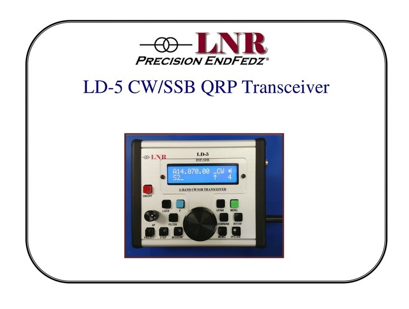
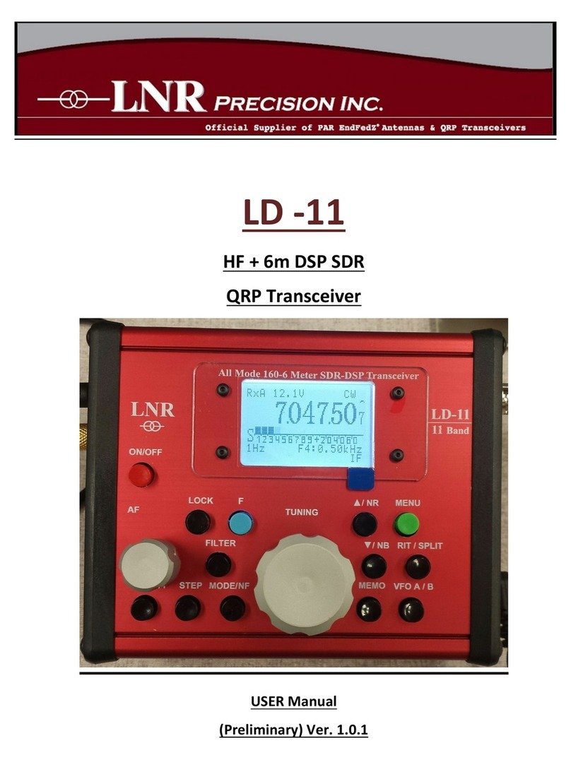
LNR FX-4A User manual

Instruction Manual
LNR FX-4a
QRP 17/20/30/40 Meter
CW/SSB Transceiver
Thank you for purchasing the LNR FX-4a
17/20/30/40 Meter CW/SSB Transceiver.
This unit is designed as a small and lightweight transceiver
perfect for portable use.
We hope you find this transceiver as fun to use as we do.
Please follow the instructions carefully and you will find this
transceiver to be a powerful, yet user-friendly unit.

FX-4A Specifications Sheet
Transceiver Weight 15.5 oz.
Current drain on Receive 250-270ma
Current drain on Transmit 1200ma
Receive/Transmit Bands 40M: 7.000.00-7.300.00 MHz
20M:14.000.00-12.350.00 MHz
30M:9.999.99-10.155.00 MHz
17M:18.068-18.168.00MHz
Display Type LCD: 128 x 64
Transmitter Max Output Power 5 Watts CW & SSB
Spurious Emissions -43dB at 5 Watts
Side Tone Pitch
Independent Side Tone Adjust
550Hz to 1.5KHz Adjustable
Receiver Sensitivity 0.3uV
Selectivity -3dB/2.6K-40dB/4.5K
Audio Output 1 Watt with 8ohm speaker
Keyer Iambic A&B Adjustable speed
from 5 to 50 wpm
Memory Storage 10 per each band; 40 total
CW Filtering:
SSB Filtering:
(CW via Hi-Per-Mite)
2.6KHz
VFO Drift <5Hz after 5 minute warm up
at 30c(<10Hz after minute op-
eration @40c)

Important Instructions
Note: All command functions in the manual will be indicated as
“Press and Hold [PH]” and “TAP”. Several switches have dual-
functions which are entered by pressing and holding [PH].
Before Initial Use: Please Read
The power requirements for the FX-4A are 12VDC to
13.8 VDC. The power plug (provided) is marked with a
white line on the positive connection to power supply
(see below).
50 Ohm antenna connection using BNC connector is
required.
8 Ohm speaker (standard or amplified) or headphone
with 1/8” stereo plug is required.
For CW Mode: Either straight key or paddle key will work
with FX-4A using 1/8” stereo type plug.
Microphone connection requires 1/8” stereo plug (Your
FX-4A purchase includes a microphone for SSB).
Initial Set-Up
1. To Power UP, plug power cord to FX-4A. Center con-
ductor is + Positive.
2. Slide power selector switch to ON. Display will signify
version 3.6 and then normal VFO display.
3. To power off, slide power selector switch to OFF.
4. Plug in speaker into port labeled PHONE.

Configuration
[PH] BAND button to access menu. Cursor is at the top/
left of CW Delay (Default).
While in Menu Mode, TAP MODE button until cursor is
on CW Mode. Turn VFO knob to select Auto (Paddle) or
Manual (Straight-Key).
Tap MODE button to CW Fre. Turn VFO knob to set side
tone adjustment (normal 0700 Hz).
Tap MODE button to CW Vol. Turn VFO knob to adjust
volume.
Tap MODE button to CW Delay. Turn VFO knob to 0.2S
(best operation).
Advance thru menu pages by tapping MODE button
until CW Key. Turn VFO knob to change to Paddle
reverse (1 Dash on Left, 2 Dits on Left)
Tap MODE button to reach second page of Menu.
Make NO adjustments on items “R BFO” - “REF 2”.
Tap MODE button to CW Key. Use VFO to change
between “mode 1” and “mode 2”. This is for Key
Reverse.
Tap M/V button to exit menu mode.
Memory Storage
The FX-4A has 10 memory stores per each of the 4
bands. To access, TAP the M/V button. “CH 00” and
Mode will be displayed in the top left corner of the
display. Rotate VFO knob to change memory storage
location number. The setting begins at CH00 and goes
through CH09 and then will roll to next band.
To Store Frequency, [PH] M/V button and an * (asterisk)
will appear right of “Mode”. Select Frequency to be
stored then tap M/V to exit and save.

Basic Operation
Connect antenna to your radio or dummy load.
Plug in your desired HAM key into port labeled KEY.
Opt. for SSB: Plug in microphone into port labeled MIC.
Before you plug in Straight key or Paddle, you may
want to get familiar with the screens and functions.
Rotate the VFO knob and notice the frequency
change.
Volume control can be increased by turning knob
clockwise. Volume will show on display as a value
between 0-63. Volume control has an additional
feature which is covered later in the manual.
Tap BAND button to desired frequency (ex. 40M, 30M,
20M, 17M). FX-4A has a VFO A and a VFO B. To toggle
between VFO A and VFO B, Tap the A/B Button. Tap
MODE button to toggle between CW, LSB, USB.
To toggle CW/A to CW/B mode, tap the A/B button.
For SSB mode, tap MODE button until USB/LSB (upper
sideband/lower sideband) is displayed.
To activate RIT feature, [PH] RIT button until RIT is
displayed. Adjustments can be made by VFO knob. To
exit RIT, [PH] RIT button.
Tap Volume knob to advance tuning rate. The rate is
1Hz - 10 Hz.
To increase to 100 Hz tuning rate, tap RIT button and
“TS” will display. To return to VFO, tap RIT again.
The FX-4A has TWO VFOs although they cannot be
used as split operation. The TWO VFOs are good to use
for CW Mode or USB/LSB operations.
S-Meter Function: The S-Meter reads signal strength,
output power, and reflective power.

NOTES
The FX-4A has an RIT function; and is accessed by [PH]
W/R switch. RIT will be display left of screen above filter
settings., Once in RIT mode there is two frequency’s
displayed. Bottom is Original VFO setting while the Top
(Large) numbers is the RIT setting. It is adjustable by
rotating the VFO knob. To exit RIT [PH] the W/R switch.
If FX-4A has a good match with antenna and power
supply voltage of 13.8 VDC, you should have 5 watts
output on CW and SSB operation.
CALL with CQ CQ CQ
Note: make sure you have configured FX-4a with your
Call. To do this, enter menu, by [PH] Band button. Cursor
down to CALL. Rotate VFO knob to select characters.
Tap Vol knob to set characters.
Cq Cq Cq can be used with your programmed call by
tap of CALL button knob.
Note: Verify H-SWR-P is set to 20 in configuration if unit
doesn't exit TX mode.
FX-4a Reset
To initiate FX-4a reset (to factory settings):
POWER OFF unit
[PH] MODE button and A/B button simultaneously while
powering up the unit.
Release after units powers up and displays “Init-OK”.

SSB Operation
FX-4A has Side Band or voice capability with a
2.6KHz filter built in. This is non-adjustable.
The included clip-on microphone has a built-in
speaker mic.
CW Operation
FX-4A has Iambic A and B functionality. To change
from A to B mode, TAP Mode switch and observe
the CW/A or CW/B at top center of display. [PH]
the A/B button to toggle between settings.
CW speed is set by [PH] Volume button and
rotating VFO knob. Speed can be adjusted
between 5 to 50 WPM. Exit speed change by TAP of
Volume knob. Note: speed is not programmed until
you exit the speed set point screen.
CW in Auto Mode
On Power-up, the CW Mode defaults to AUTO
which is paddle mode. If operator wishes to
operate in manual, [PH] BAND, Tap MODE button
until CW Mode is displayed. Use VFO knob to adjust
between Auto and “Manu” for manual. Tap M/V to
exit and save.
[PH] Volume Knob to display paddle speed. Turning
the VFO knob will then allow you to adjust the
speed between 5 and 50 WPM. Tap Volume knob
again to store setting.

Menu Features
[PH] BAND button until menu display appears.
*Indicates menu feature is adjustable.
Note: only * indicated items should be adjusted. Other
items should not be adjusted beyond their stated values.
R BFO: 8.998.600 Hz
T BFO: 8.999.300 Hz
USB BFO: 9.000.800 Hz
LSB BFO: 8.997.800 Hz
REF1: 30.000.000Hz
REF2: 50.000.000Hz
*CW KEY: (Paddle reverse) Mode 1 / 2
*CW Delay: 0.1Sec to 1.5Sec
*CW Vol (Sidetone): 01 to 10
*CW Fre (Pitch): 0550Hz
1500 Hz
*CW Mode: Auto = Paddle
Manu= Straight/Bug
*H-VWR-P: 20
*Light:
(Backlit Timer)
Delay 1Sec - 9Sec/
Always Open
*IF: Default - 0-0.700Hz
*Call: (Your Callsign) (Rotate VFO knob
and TAP Vol. to move
to next char) Leave
one space after call for
letter K

Menu Notes
All settings are adjustable however certain settings
are for informational use only should not be
changed as this will affect selective and off
frequency operation.
The following settings should NOT be changed.
No Set Point Change Required.
R BFO: 8.999.300Hz
T BFO: 9.000.000Hz
USB BFO: 9.001.500Hz
LSB BFO: 8.998.500Hz
REF1: 30.000.000Hz
REF2: 50.000.000Hz
CW External Filtering
If operating in CW mode, filtering is handled by
the included Hi-Per-Mite external filter kit. The Hi
-Per-Mite is an active audio CW filter designed
by David Cripe, NM0S. Please visit http://
www.4sqrp.com/HiPerMite.php for detailed
instructions and documentation on the Hi-Per-
Mite.
As stated on their webpage, “the HI-PER-MITE is
a HIgh-PERformance SMALL audio filter. It is
designed to be very versatile, have low parts
count, be inexpensive, yet provide outstanding
performance.”

We hope you enjoy your new
LNR FX-4A 17/20/30/40 Meter
QRP Transceiver.
For technical assistance, please
contact us at information below:
LNR Precision, Inc.
Randleman, NC 27317
www.LNRprecision.com
E-Mail Ldr[email protected]
“This is a flexible design that can be used as a
stand-alone unit driving headphones, earbuds, or
speakers, or it can be easily integrated into an
existing receiver needing additional CW filtering
(see manual for details). “
Hi-Per-Mite Specifications (4 States QRP)
Bandwidth: 200 cycles at the -3 DB bandwith points.
Center Frequency: The center frequency in the passband is 700 HZ
Signal Gain: 0 dB to 50 dB, user selectable
No Ringing or Buzz: Nice, smooth audio - care has been taken in the
design to eliminate ringing.
Versatile: Drives speaker, earbuds, or headphones. Use standalone or
install inside rig.
Audio Power: 500 mW into 8 ohms, from 9v supply
DC Power: 5 to 13 VDC at less than 15 mA
Table of contents
Other LNR Transceiver manuals