LNS SC 500 User manual

OIL MIST PURIFIERS
Part spray cabin SC 500
INSTRUCTION MANUAL

LNS ITALIA s.r.l. Instruction manual series SC 500 page 2 di 21 –05-2014
Contents
Contents...............................................................................................................................................2
1. General information.........................................................................................................................3
1.1. Contents and symbols .......................................................................................................................3
1.2. Safety................................................................................................................................................3
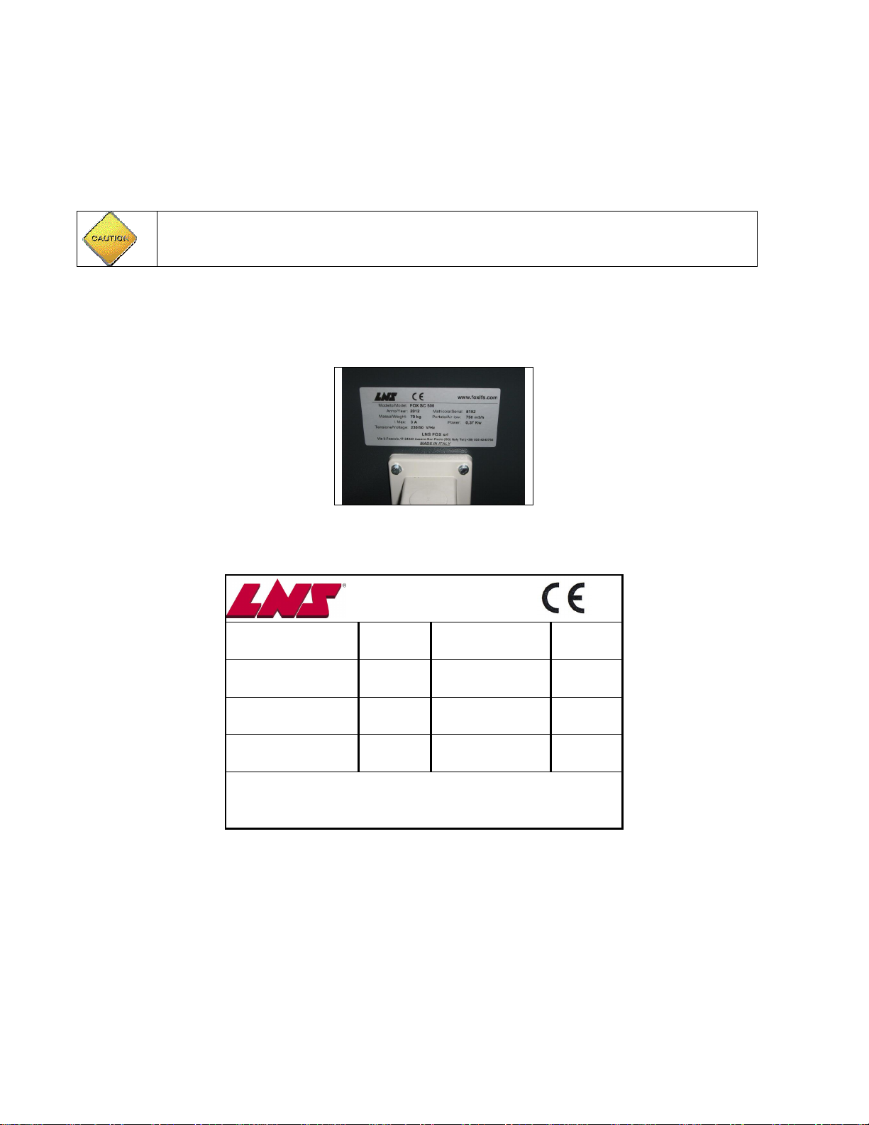
1.2.1 Information label description and placement...............................................................................................3
1.2.2. Main safety regulations .............................................................................................................................4
1.3. Unit range of use ...............................................................................................................................4
1.3.1. Proper uses ..............................................................................................................................................4
1.3.2. Improper uses...........................................................................................................................................4
1.3.3. Operating conditions.................................................................................................................................5
1.4. Machine identification and technical specifications.............................................................................5
1.5. Supply contents.................................................................................................................................5
1.6. Warranty............................................................................................................................................6
2. Handling, transport and storage.....................................................................................................6
2.1. Handling and transporting packed material........................................................................................6
2.2. Unit handling and transport................................................................................................................6
2.3 Storage...............................................................................................................................................6
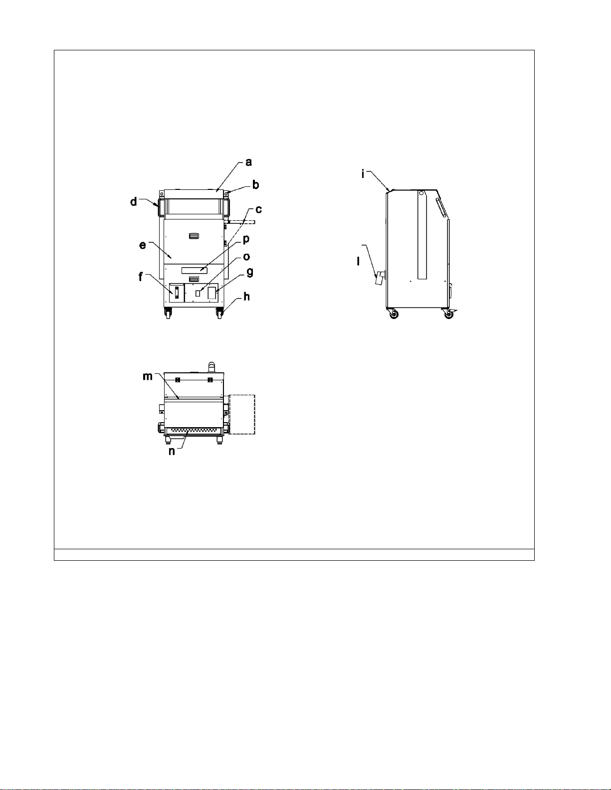
3. Unit description and technical specifications ...............................................................................7
3.1. General features................................................................................................................................8
3.2. Electrical features..............................................................................................................................8
3.2.1. 3-phase motor...........................................................................................................................................8
3.2.2. Single-phase motor..................................................................................................................................8
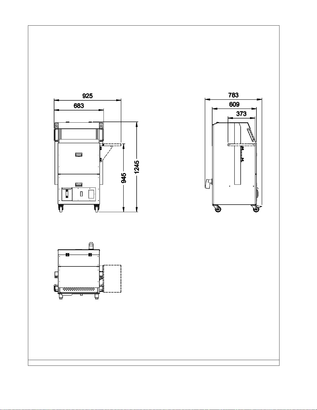
3.3 Dimensions.........................................................................................................................................9
4. Installation .....................................................................................................................................10
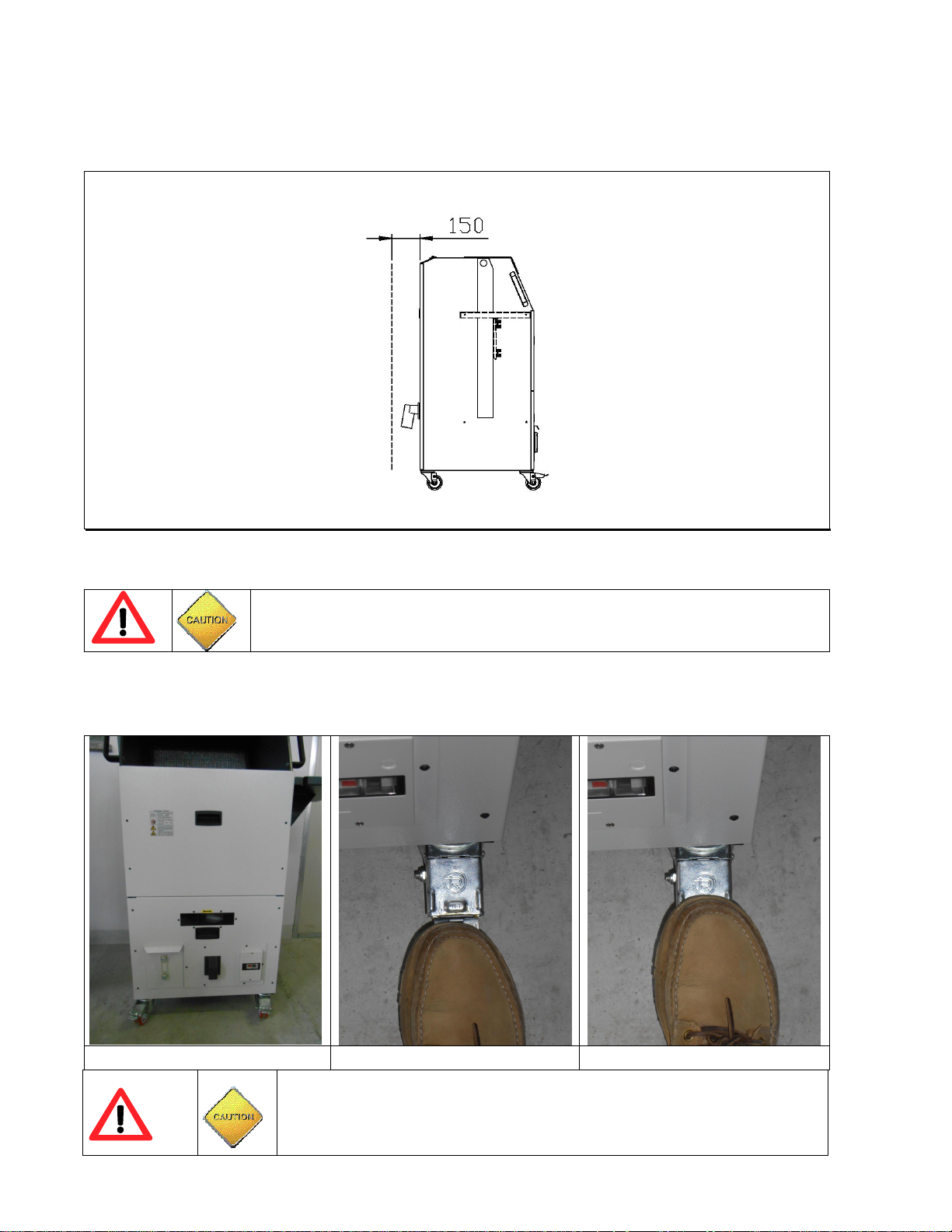
4.1. Minimum installation space..............................................................................................................10
4.2. Support floor, and wheel lock...........................................................................................................10
4.3 Preload siphon..................................................................................................................................11
4.4 Using side tray..................................................................................................................................11
4.5. Electrical connections......................................................................................................................12
4.5.1 Rotation control for the version with three-phase motor............................................................................12
4.5.2. Checking the setting of the motor protector .............................................................................................13
4.5.3. Available voltages/frequencies................................................................................................................13
4.5.4. Motor protector settings chart..................................................................................................................14
5. Unit use ..........................................................................................................................................14
5.1. Starting and stopping.......................................................................................................................14
6. Maintenance...................................................................................................................................15
6.1 Maintenance chart............................................................................................................................15
6.2. Routine maintenance.......................................................................................................................15
6.2.1. Pre-filter and filter tray maintenance........................................................................................................15
6.2.2. Main filtration cartridge maintenance.......................................................................................................16
6.2.3. Condensed liquid container.....................................................................................................................18
6.3. Periodic checks................................................................................................................................18
6.4. Troubleshooting...............................................................................................................................19
6.5. Disposal and scrapping....................................................................................................................19
6.5.1 Disposal of consumables .........................................................................................................................19
6.5.2 Scrapping ................................................................................................................................................19
7. Spare parts.....................................................................................................................................20
7.1 Spare filters ......................................................................................................................................20
8. Wiring diagrams ............................................................................................................................21

LNS ITALIA s.r.l. Instruction manual series SC 500 page 3 di 21 –05-2014
1. General information
1.1. Contents and symbols
Dear customer, this manual contains all the indications and suggestions necessary for the installation, use and
maintenance of SC series part spray cabin.
The indications in this manual can be divided into:
A) Regulations on Personal Safety
Partial or total non-compliance with these regulations may pose a serious hazard to the safety or
health of exposed persons
B) Regulations on Unit integrity
Partial or total non-observance of these regulations may result in damage to the unit and/or other
machines connected to it
C) Other indications and
Notes
of particular importance
Notes of particular importance that are not included in the two previous classifications
1.2. Safety
Before operating the unit described below, we ask that you carefully read this manual, paying particular attention to all
the Regulations on personal safety and unit integrity
This unit was designed and produced in compliance with the following European Community safety directives:
·Machine directive 2006/42/EEC
·Low Voltage Directive 2006/95/EEC
·Electromagnetic Compatibility Directive 2004/108/EEC
In compliance with the safety directives, each residual risk identified during the risk analysis has been inserted and
highlighted in this document.
Specific hazard and/or warning labels have been placed on the unit for additional safety.
“Personal safety –unit integrity”
LNS ITALIA is not liable for any damage to things or injuries to persons caused by non-
observance of any safety regulations.
1.2.1 Information label description and placement
A
Label that
emphasises
the
importance of
reading the
instruction
manual where
the main
safety
warnings on
electric and
mechanical
risks can be
found.
B
Serial number label which, in
addition to identifying the machine,
contains data on: weight, power,
electric current draw and air flow
rate.
C
Label with filtration data for the
main filter cartridge
D
Label indicating the impeller
rotation direction
E
Label:optical sensor for start
F
Label: max load on lateral tray
(8kg)
Fig. 1a Main warning labels

LNS ITALIA s.r.l. Instruction manual series SC 500 page 4 di 21 –05-2014
Fig. 1b Main label position
1.2.2. Main safety regulations
a) Consult this instruction manual thoroughly before installing, using or servicing the unit
b) Make sure the unit is isolated from the power supply (see maintenance chapter) before servicing it
c) Wear suitable protective (accident-prevention) clothing during installation and maintenance.
1.3. Unit range of use
1.3.1. Proper uses
The SC series spray cabins are used to vacuum spray mechanical parts dirtied with oil and/or metallic powder in user
safety conditions.
1.3.2. Improper uses
·Extraction of potentially flammable fumes
·Extraction of potentially explosive substances
·Extraction of solvents, paint or other adhesive substances
·Extraction of acid or base substances or those with corrosive properties
“Personal safety –unit integrity”
LNS ITALIA is not liable for any injuries to persons or damage to things caused by
improper use of the unit.

LNS ITALIA s.r.l. Instruction manual series SC 500 page 5 di 21 –05-2014
1.3.3. Operating conditions
Allowed operating conditions:
·Temperature: from 5 to 40 °
·Ambient air relative humidity: from 30 to 85%
·Extracted air relative humidity: from 30 to 98%
·Maximum installation altitude: 1000 m above mean sea level
"Unit integrity"
LNS ITALIA is not liable for any damage to the unit due to use in operating conditions different from
the ones specified above.
1.4. Machine identification and technical specifications
The main identification data of the unit is listed on the plate located in the rear near the electrical supply input.
Fig. 2 identification plate
The following data appears on this plate
Modello/Model
-
Matricola/Serial
-
Anno/Year
-
I max [A]
-
Portata/Air Flow
[m3/h]
-
Potenza/Power [kW]
-
Massa/Weight [kg]
-
3~[V/Hz]
-
LNS Italia srl
Via Ugo Foscolo 17- 24052 Azzano San Paolo - (BG) Italy
Ph.(+39) 035 4243756
1.5. Supply contents
The following are provided with the unit:
·this manual
·test certificate
·CE compliance declaration

LNS ITALIA s.r.l. Instruction manual series SC 500 page 6 di 21 –05-2014
1.6. Warranty
The LNS ITALIA supplier guarantees its products to be free of defects that may hinder normal use for a period of 24
months starting from the date of installation which, unless otherwise stipulated between the parties, must not take
place more than sixty days from the delivery date.
The warranty is ex works and, upon discretion of the supplier, is limited to repair or total replacement of products that
prove to be objectively defective or unsuitable for the use for which they were designed.
The buyer undertakes to communicate any irregularity found within 7 days to the supplier and to make the product
deemed defective available to the supplier. In order to prevent further damage, or upon specific request from the
supplier, the buyer undertakes to not use the unit from the moment the irregularity is found.
Failure to communicate the irregularity within the indicated time or further damage to the unit caused by use may,
upon the supplier's discretion, reduce or entirely void the warranty.
The warranty is ex the supplier's factory or ex works unless otherwise specified by the supplier.
In the event of repair work done on the customer's premises, the warranty does not cover the costs of meals,
accommodations and travel.
The warranty does not cover all imperfections or defects attributable to specific requests, material or immaterial by the
buyer or other persons acting in name of and on behalf of the buyer himself.
The warranty does not cover damage due to improper or non-compliant use of the unit, including improper use or use
not covered by the technical manual that accompanies the product.
The warranty is not valid for material subject to normal wear and tear or consumption (e.g. filter elements), except for
evident manufacturing defects that obstruct use.
Attempts to repair the unit by external personnel or personnel not directly commissioned by LNS ITALIA will reduce or
entirely void the warranty.
Except in the event of wilful misconduct or gross negligence attributable to LNS ITALIA, compensation cannot exceed
the value of the product that caused the damage.
ITALIA LNS is not liable for damages caused by failed or delayed productions due to unit malfunction or breakdown.
2. Handling, transport and storage
2.1. Handling and transporting packed material
“Personal safety –unit integrity”
LNS ITALIA is not liable for any injuries to persons or damage to things caused by
handling procedures that are non-compliant or contrary to safety standards.
The unit must be handled by properly trained personnel with appropriate lifting and transport equipment chosen
according to the weight and shape of the load.
Equipment weight is indicated on the machine plate. Any special handling instructions may be indicated on the single
packages.
2.2. Unit handling and transport
User appropriate lifting equipment for handling.
In the event of need, each unit can be lifted with a forklift.
“Personal safety –unit integrity”
Lifting must be done by trained personnel using equipment with suitable features for
lifting the load
2.3 Storage
Keep units in a dry place away from direct exposure to the elements in the following environmental conditions:
·Temperature: 0°C –40°C
·Relative humidity: 30 –80 %

LNS ITALIA s.r.l. Instruction manual series SC 500 page 7 di 21 –05-2014
3. Unit description and technical specifications
Fig. 3 U
nit description
a) Polycarbonate transparent cover
b) Start/stop button
c) Closable right or left side tray
d) Manoeuvre handles
e) Filter cartridge access door
f) Liquid container with level indicator
g) Fuse box with motor circuit breaker
h) Castor wheels with brake
i) Pre-filter access door
l) Filter cartridge
m) Wall socket
n) LED tube lighting
o) Perforated part holder
p) Window to control motor rotation (three phase version)

LNS ITALIA s.r.l. Instruction manual series SC 500 page 8 di 21 –05-2014
3.1. General features
Model
SC 500
Frequency
[Hz]
50 60
Nominal air flow rate
[m
3
/h]
-
[cfm]
750 900-530
Static
pressure
[Pa]
610 890
Sound level
[dB(A)]
67 69
Rotation speed
[min
-
1
]
2790 3350
Weight
[kg]
70
3.2. Electrical features
3.2.1. 3-phase motor
Standard model
SC 500
Shaft height
71
Structural form
B5
No. poles
2
IP Protection Rating
55
In
sulation class
F
Power (kW) 0.37-0.44
Absorption
230V
-
50 Hz
[A]
2.04
Absorption
400V
-
50 Hz
[A]
1.09
Absorption
200V
-
50 Hz
[A]
1.86
Absorption
220V
-
60 Hz
[A]
2.04
Absorption
230V
-
60 Hz
[A]
2.04
Absorption
400V
-
60 Hz
[A]
1.18
Absorption
460V
-
60 H
z
[A]
1.09
3.2.2. Single-phase motor
Standard model
SC 500
Shaft height
71
Structural form
B5
No. poles
2
IP Protection Rating
55
Insulation class
F
Power (kW) 0.37/0,44
Current draw 230V
[A]
3
Current draw 115V
[A]
7

LNS ITALIA s.r.l. Instruction manual series SC 500 page 9 di 21 –05-2014
3.3 Dimensions
Fig. 4 Dimensions (mm)

LNS ITALIA s.r.l. Instruction manual series SC 500 page 10 di 21 –05-2014
4. Installation
4.1. Minimum installation space
To permit air exhaust, the back must be positioned at least 150 mm from the wall or other surfaces that reduce or
hinder air exhaust.
Fig. 7 Minimum space for installation (mm)
4.2. Support floor, and wheel lock
“Personal safety –unit integrity”
To prevent injuries to persons or damages to things, unit installation must be done by
specialised personnel.
Identify a flat installation site before installing the units.
The purifier can be locked on the work site by pressing the front brake lever fig. 5b)
To release the brakes, use the release lever as indicated in figure 5c).
Fig.5a Fig.5b Fig.5c
“Personal safety –unit integrity”
Since equipped with castor wheels, the cabin should only be used on flat
surfaces, not slanted!!
LNS is not liable for any injuries to persons or damage to things caused by use
of the purifier on inclined surfaces

LNS ITALIA s.r.l. Instruction manual series SC 500 page 11 di 21 –05-2014
4.3 Preload siphon
Before using the spray cabin it is necessary to preload the drain trap as shown in the following steps:
- Remove the upper grille (Fig. 5a).
- Slowly pour about a liter of whole oil (do not use emulsions) in the collecting tray chips (5b).
- After a few minutes verify that the excess oil is drained into the container recovery (5c).
Fig.5d Fig.5e Fig.5f
"personal safety- unit integrity"
Failure of preload the siphon can compromise the life of the filters and the level of air
filtration in output.
Do not use emulsions but only neat oil for the preload of the siphon.
4.4 Using side tray
To use the side tray:
- Lift the tray by turning it around the hinge support
- Turn the holder and lock it in place between the two safety pins
- Check that the tray is fully locked in place.
"Personal safety –unit integrity"
In order to avoid damage to persons or property the maximum load that can be placed on
the tray-pieces is 8 kg.
Do not under any circumstances exceed the maximum load of 8kg.
Fig.5g Fig.5h Fig.5i

LNS ITALIA s.r.l. Instruction manual series SC 500 page 12 di 21 –05-2014
4.5. Electrical connections
“Personal safety –unit integrity”
To prevent injuries to persons or damage to things, the unit electrical connection must be
done by qualified electricians in compliance with safety procedures.
Before doing the electrical wiring, make sure the line is not powered and cannot be turned
on by external personnel
The unit is equipped with an equipotential protection circuit in compliance with standard EN 60204-1.
In order to have an effective protection system against indirect contacts, the power line must be outfitted with
a circuit breaker that will automatically interrupt power in the event of an insulation failure, in compliance with
the regulations 413.1 of standard IEC 364-4-41.
Unless otherwise indicated on the identification plate, the electrical wiring must be done with cables (with adequate
section and characteristics in compliance with the location).
The cabin comes complete with one of the following IEC 309 plugs according to the power mains:
•3P +PE
•P+N+PE
4.5.1 Rotation control for the version with three-phase motor
After connecting the power cable, check the motor rotation direction on three-phase versions. Proceed as follows for
this check:
- Press the start button located on the breaker (Figure 6)
- Place one foot below the proximity sensor (Figure 6)
- Press the start/stop button twice in a tow and make sure impeller rotation (clockwise rotation extraction side)
matches the direction of the arrow located at air inlet (fig 11 f).
- If the arrow and the direction of the impeller rotation do not match, after having sectioned the power line,
invert the two-phase power supply connection.
- Restart the unit and check that the rotation direction matches the arrow.
Figure 6a) Front view of cabin Fig.6b) View panel with proximity
sensor for starting Fig.6c) Motor protection switch
(breaker)

LNS ITALIA s.r.l. Instruction manual series SC 500 page 13 di 21 –05-2014
Fig.6d) Proximity sensor for starting
Fig. 6e) Start-stop green button ) Fig. 6f) Control of the impeller
rotation
Personal safety –unit integrity
Install a protective device that will automatically cut off the power in the event of a fault in
the unit or the power supply circuit itself.
Note
For special electrical plants (remote controls, disconnectors, etc.), refer to the attached documents.
4.5.2. Checking the setting of the motor protector
Should the motor protector need to be checked or calibrated:
- Unscrew the cover fastening screws
- Adjust motor protector calibrations (setting the absorption value printed on the motor plate) using the
regulation screw.
- Reinstall the cover and tighten the fastening screws
4.5.3 Available voltages/frequencies
The spray cabin is available in the following voltages/frequencies:
- 230 V 50 Hz Single-phase (standard version)
- 115 V 60 Hz Single phase
- 400 V 50 Hz Three-phase
- 200 V 50 Hz 220-230 V 60 Hz Three-phase
- 400-460 V 60 Hz Three-phase
7a) Unscrew the fastening screws
7b) Remove the motor protector cover
7c) Motor protector adjustments

LNS ITALIA s.r.l. Instruction manual series SC 500 page 14 di 21 –05-2014
4.5.4. Motor protector settings chart
Model
Connection voltage
[V]
Electric motor power
(kW)
Current draw
[A]
Motor protector settings
[A]
SC 500
230V 50 Hz Single-
phase 0.37 3 3
115V-60 Hz Single
phase 0,44 7 7
400V 50 Hz 3Ph 0.37 1.09 1.09
200 V 50 Hz 3Ph 0.37 1.86 1.86
220-230V 60 Hz-3 Ph 0.44 2.04 2.04
400 V 60 Hz 3Ph 0.44 1.18 1.18
460 V 60 Hz 3Ph 0.44 1.09 1.09
5. Unit use
5.1. Starting and stopping
To start the unit:
·Press the motor protector switch start button located at the bottom right
·Press the green start/stop button located on the right or left hand side of the cabin
·Place one foot below the proximity sensor for start.
8a) motor protector switch
8b) green start/stop button
8c) proximity sensor for start
The LED light tube turns on to indicate that the cabin is running.
The spray cabin will automatically turn off after about 3 minutes.
Press the green button if you want to stopping in advance the functioning of cabin without having to wait the
intervention of sensor.

LNS ITALIA s.r.l. Instruction manual series SC 500 page 15 di 21 –05-2014
6. Maintenance
“Personal safety
–
unit integrity”
·Before servicing the unit:
- Press the stop button on the motor protector switch, lock out the start up button,
close the protective lid and remove the keys.
- Isolate the unit from electrical power sources making sure that no one can restore
power; to this purpose, insert the padlocks and all other required devices on the
power line.
- Use signs or other appropriate means to indicate that maintenance is being done on
the unit.
- Wear proper protective clothing such as gloves, safety shoes, etc. while maintenance
is being done.
·To prevent injuries to persons or damage to things, unit maintenance must be
done by specialised personnel in compliance with safety procedures.
·Before using the nuts and bolts, make sure they are in perfect condition,
otherwise replace them with new components that are identical to the original
ones. Self-locking nuts must always be replaced with new components.
Note
The below maintenance intervals are indicative and refer to average situations as they may change
considerably according to the type and quantity of pollutant in the air extracted.
6.1 Maintenance chart
Cleaning
Replacement
Inspection/check
PREFILTRATION
Condensed liquid
filter tray As needed
- 500 h
Metal prefilter As needed
1000 h
Synthetic pre-filter
As needed
1000 h
MAI
N FILTRATION
Cartridge filter As needed
2000 h
6.2. Routine maintenance
6.2.1. Pre-filter and filter tray maintenance
Prefilters
- To remove pre-filters, rotate the hinged door located at the top
- Remove the metal and synthetic pre-filters.
The metal filter can normally be cleaned and reused without requiring replacement.
We recommend replacing the synthetic filter.
Alternatively, the synthetic filter can be cleaned using grease cutting dishwashing detergent, rinsing and letting the
filter drip dry or dry with a jet of compressed air.
Filter tray
- Remove the support grid
- Remove the filter tray
- Remove any scraps and sludge from the tray
- Accurately clean drain holes to allow liquid to drain.
- Remove any chips from the oil drain hole located behind the prefilters
- Reinstall the tray and grid support

LNS ITALIA s.r.l. Instruction manual series SC 500 page 16 di 21 –05-2014
9a Hinged door
9b Pre-filter removal
9c Metal and synthetic pre-filter
9 d) support grid removal
9 e) Filter tray removal
9 f) tray hole details
9 g) hole located behind the prefilters 9 h) reinstall the tray 9 i) reinstall the grid
6.2.2. Main filtration cartridge maintenance
"Personal safety"
Do not remove the main filter for any reason while the unit is on.
Removing the main filter while the unit is operating will expose you to hazards of a mechanical nature
(dragging, cutting, shearing etc.) due to rotation of the impeller.
To remove the cartridge from its housing:
- Unscrew the filter access panel fastening screws and remove the panel, lifting up and pulling out fig. 10 a,b)
- Remove the grate and filter tray to access the cartridge release system. Fig 10 c-d)
- Using a 17 mm wrench, release the cartridge and remove it fig 10 d-f-g-h)
"Note"
The cartridge in glass microfibre cannot be regenerated and for this reason must be replaced when
necessary.
Fig. 10a) Unscrew the panel
fastening screws
Fig. 10b) Opening the filter panel
Fig. 10c) Grate removal

LNS ITALIA s.r.l. Instruction manual series SC 500 page 17 di 21 –05-2014
Fig. 10d) Tray removal
Fig. 10d) Releasing the cartridge
Fig. 10f) Cartridge lock system detail
Fig.10g).
Lock system detail Fig.10h)
Cartridge removal Fig.10i)
Cartridge extraction
To install the cartridge in its housing:
- Clean the cartridge housing and remove any oil deposits or scraps
- Insert the new cartridge and push it fully in with both hands until it hits the two limit stops
- Lock the cartridge in place by rotating the lock screws clockwise
- Insert the tray
- Insert the grate
- Install the panel from the top and secure it with the fastening screws
Fig. 10 l) Cartridge insertion
Fig. 10 m) Cartridge lock
Fig. 10 n) Cartridge lock
Fig. 10 o) Tray insertion
Fig. 10 p) Grate insertion
Fig. 10 q) Securing the panel

LNS ITALIA s.r.l. Instruction manual series SC 500 page 18 di 21 –05-2014
6.2.3. Condensed liquid container
The cabin is equipped with a condensed liquid container with level indicator.
Before liquid in the cabin reaches the maximum level (indicated by the red line) remove the container from the cabin
and empty it.
For easier extraction, slightly lift and pull the container outward.
After emptying/cleaning, reinstall the container in its housing.
11) Cabin overall view
11 b) Liquid container
11 c) Liquid container removal
6.3. Periodic checks
“Personal safety
–
unit integrity”
Carry out periodic checks following the below timetable to prevent hazards to exposed
persons and/or damages to the unit
Every 5000 operating hours, the following checks should be conducted:
·Integrity of casings, sheaths and electric cables
·Continuity of equipotential protection circuit
·Integrity of the support structural parts of the motor-impeller unit
·Tightness of motor bolts
·Tightness of impeller screws
If irregularities arise, have the necessary repairs made immediately. Do not hesitate to contact our technical
department for any doubts or questions.

LNS ITALIA s.r.l. Instruction manual series SC 500 page 19 di 21 –05-2014
6.4. Troubleshooting
Possible problems and relative solutions to adopt follow. Our technical department is at your complete disposal for any
doubts.
“Personal safety –unit integrity”
·Before servicing the unit:
- Press the OFF button on the motor protector switch.
- Cut off the device from power sources (unplug) and make sure no one can restore
power. For this purpose, install a padlock or any other device foreseen on the
power line.
- Use signs or other appropriate means to indicate that maintenance is being done on
the unit.
- Wear proper protective clothing such as gloves, safety shoes, etc. while
maintenance is being done.
·To prevent injuries to persons or damage to things, unit maintenance must be
done by specialised personnel in compliance with safety procedures.
·Before using the nuts and bolts, make sure they are in perfect condition,
otherwise replace them with new components that are identical to the original
ones. Self-locking nuts must always be replaced with new components.
Problem
Possible cause
Solution
Insufficient extraction
Clogged filters
·
Remove pre-filters and check whether extraction
returns to normal levels. If necessary, replace
and/or clean pre-filters.
·If extraction remains insufficient even after pre-
filters are removed, check cartridge conditions and
replace the cartridge if necessary
Air exhaust grate clogged
·
Remove the object obstructing the purified air
outlet
·Move the cabin away from the wall/object that
blocks air exhaust
Unsatisfactory air
purification
Main filter deteriorated or
incorrectly installed Make sure the filter is correctly positioned and tightened;
replace the filter or seal if necessary
Excessive vibration
Unbalanced impeller
and/or worn bearings Turn off the unit and contact our technical department.
Motor shock absorbers
worn or broken Check shock absorbers, replace if broken or worn.
Abnormal noise Worn bearings Replace electric motor bearings
Interference between
impeller and air inlet or
other unit parts.
Turn off the unit immediately, find the reason for the
interference. Contact our technical department.
Motor protector switch
intervenes
Incorrect setting Check unit's electric current draw level and use the small
graduated wheel on the switch to set the correct level
Excessive motor electric
current draw or motor
short circuits
Find the causes of excessive current draw and correct
them. Replace the motor if it short circuits.
6.5. Disposal and scrapping
"Note"
To safeguard the environment and avoid fines, we recommend and ask that you abide by the
following indications scrupulously
6.5.1 Disposal of consumables
Materials such as filters and seals that are dirty with oil must be disposed of in compliance with the laws in force on
the matter of special waste.
6.5.2 Scrapping
In order to maximise recycling of raw materials in the unit, for scrapping we recommend that you take the unit to
specific scrapping companies

LNS ITALIA s.r.l. Instruction manual series SC 500 page 20 di 21 –05-2014
7. Spare parts
7.1 Spare filters
The following is a list of the various available filters.
Description
Code
Metal prefilter
350394000
Synthetic pre-filter
350395000
Main cartridge
350148000
Table of contents
Popular Air Cleaner manuals by other brands

Levoit
Levoit LV-PUR131S quick start guide

OION Technologies
OION Technologies APB-5000 Use & care instructions

Black & Decker
Black & Decker BAPT01 instruction manual

Honeywell
Honeywell HHT-100 - HEPA Air Purifier Safety guide

ifs
ifs IFE 2000 operating instructions

Boneco
Boneco Ionic Pro Turbo TA500 instructions