5 - ROUTINE MAINTENANCE
WARNING :
Risk of releasing hazardous material if maintenance
is not performed.
5.1 - Daily
Inspect the unit:
1. power cord is not broken, frayed or worn, and the plug is fully
engaged at the wall outlet.
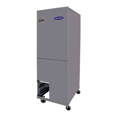
2. casters are locked.
3. red lter/obstruction indicator is not illuminated.
4. unit operates without excessive vibration or unusual noises.
5. exible exhaust ducting (if used) is not kinked or damaged,
and securely attached at both ends.
5.2 - Cleaning
Routinely clean any dust and contaminants from the exterior of
the unit and power cord with a mild cleaner. Do not use excessive
liquid neither running or high pressured water. Decontaminate as
necessary with a facility -and EPA- approved disinfectant.
5.3 - Filter Replacement
CAUTION :
PERSONAL PROTECTION
Consider the lters contaminated. Wear appropriate
Personal Protective Equipment (gown, gloves,
respirator, glasses, etc) when changing lters, and
seal them immediately in plastic bags for disposal.
Filter cells are ammable products, the risk of res
increases depending on the elements ltered by the
media.
Keep the lters away from ames.
WARNING :
MOVING PARTS & SHARP EDGES HAZARD
Failure to follow this warning could result in personal
injury. Do not place objects on top of the discharge
plenum.
Keep hands and face away.
Rotating blower wheel can cause serious injury.
Always use cut-resistant gloves when handling.
NOTE: Before replacing lters, check to make sure there is
nothing impeding the airow into the unit. Check under the
unit for paper, rubbish, etc., that may be trapped on the intake
side.
NOTE: If your facility already has a procedure in place for
replacing lters, follow your procedure. If guidance is needed,
then follow these instructions.
5.4 - Pre-Filter
The pre-lter must be replaced every 90 days.:
1. Put on Personal Protective Equipment.
2. Move the power switch to the OFF (O) position.
3. Unplug the power cord from the unit, and from the wall outlet.
4. Listen to make sure the blower wheel has stopped spinning,
then remove the side door panel.
5. Remove the lter holding frame on top of lters (Fig. 7).
6. Remove the HEPA lter and immediately put it inside an
approved containment bag.
7. Remove the pre-lter from cabinet and immediately put it inside
an approved containment bag. Dispose as ordinary industrial
waste.
8. Replace the pre-lter (See P.10 for reference). Note the air-ow
arrows on the lter and make sure they point up. Replace the
bottom front door panel. Replace the HEPA lter
9. Position the new HEPA lter into the unit with the gasket on
the lter facing up, on the discharge side of the lter. Make
sure the HEPA lter is centered and the edges align with the
pre-lter for a complete seal.
10. Replace the lter holding frame (Fig. 7).
11. Inspect the lter for a complete and tight t.
12. Replace the door panel.
13. Plug in the unit and rock the power switch up to the ON (I)
position.
5.5 - HEPA Filter
If the red indicator light is illuminated and did not extinguish after
prelter replacement, order a new lter within 2 weeks maximum.
See P.10 for reference.
1. Put on Personal Protective Equipment.
2. Move the power switch to the OFF (O) position.
3. Unplug the power cord from the unit, and from the wall outlet.
4. Listen to make sure the blower wheel has stopped spinning,
then remove the side door panel.
5. Remove the lter holding frame on top of lters (Fig. 7).
6. Remove the HEPA filter and immediately put it inside an
approved containment bag. Dispose as ordinary industrial waste.
7. Position the new HEPA lter into the unit with the gasket on
the lter facing down, on the discharge side of the lter. Make
sure the HEPA lter is centered and the edges align with the
pre-lter for a complete seal.
8. Replace the lter holding frame (Fig. 7).
9. Inspect the lter for a complete and tight t.
10. Replace the door panel.
11. Plug in the unit and rock the power switch up to the ON (I)
position.
Fig. 6 - Filters
Filter holding frame
HEPA Filter
Pre-lter
Fig. 7 - Filter holding frame
7
