WARNING
1. This product is made for general industry. Contact SMC before use, if you are planning to use for
other purposes.
2. Use under specified voltage and temperature.
Voltage out of specification may cause malfunction, breakage, electric shock and fire.
3. Use clean compressed air for fluid.
The construction of this product is not explosion proof. Do not use fluid such as inflammable gas or
explosive gas or use in atmosphere including such a gas. It may result in fire or explosion.
When using fluid other than compressed air, contact SMC.
CAUTION
1. This product has not been washed.
When bringing into clean room. Use after confirming its purification level after flushing.
WARNING
1. Get required space for maintenance, wiring and piping at installation.
Install connector and One-touch fitting for air supply to be able to eliminate and mount cable and tube.
Do not bend cable and tube with steep angle but fix them straight considering minimum bending
radius to prevent forcible stress applied to installation base of connector and One-touch fitting.
Forcible installation and elimination may cause malfunction, broken wire, fire and air leakage.
Minimum bending radius: Power supply cable
20mm
Sensor cable
20 mm
Note: Here is allowable bending radius when fixing wiring at 20
o
C. If bending cable at lower
temperature, it may apply forcible force to connector even with minimum bending radius or more.
See instruction or catalog for minimum bending radius fo tube.
2. Install on the plane face.
Forcible force may apply to frame or case due to concave and convex or deformed mounting face and
large level gap, and it may cause breakage or operation failure. Also, dropping or strong impact may
cause operation failure or accident.
3. Do not install with strong electromagnetic source.
Installation with strong electromagnetic source may cause malfunction. Install on the different panel
or separate the mounting.
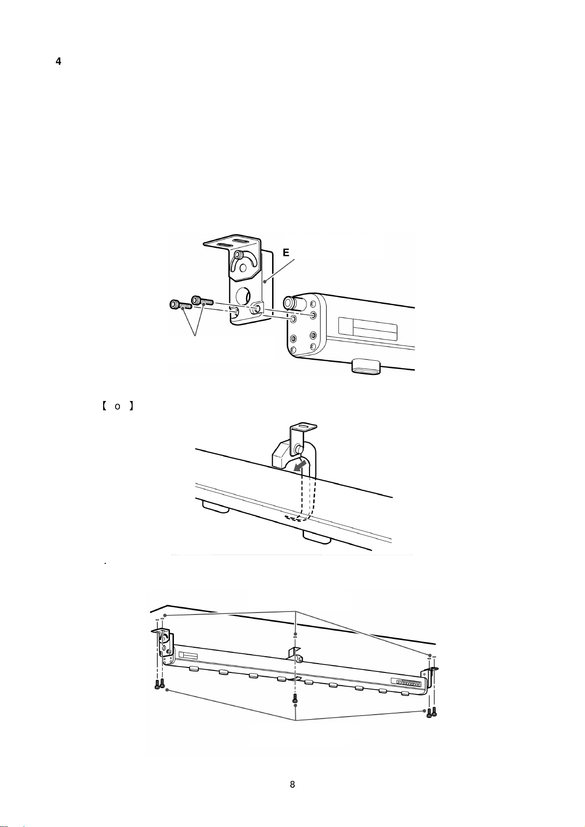
4. Tighten within the specified torque.
tightening torque: See “4. Installation”
When exceeding the tightening torque, mounting screw and mounting bracket etc. might be broken.
The screw might loosen for less than range of the tightening torque.
5. Do not touch electrode needle with finger or metal tool directly. It may cause injury.
If electrode needle or cartridge is damaged by tools, it will not only interfere the specification function
and performance but also may cause operation failure or accident.
6. Be sure to install and adjust after power supply is stopped.
CAUTION
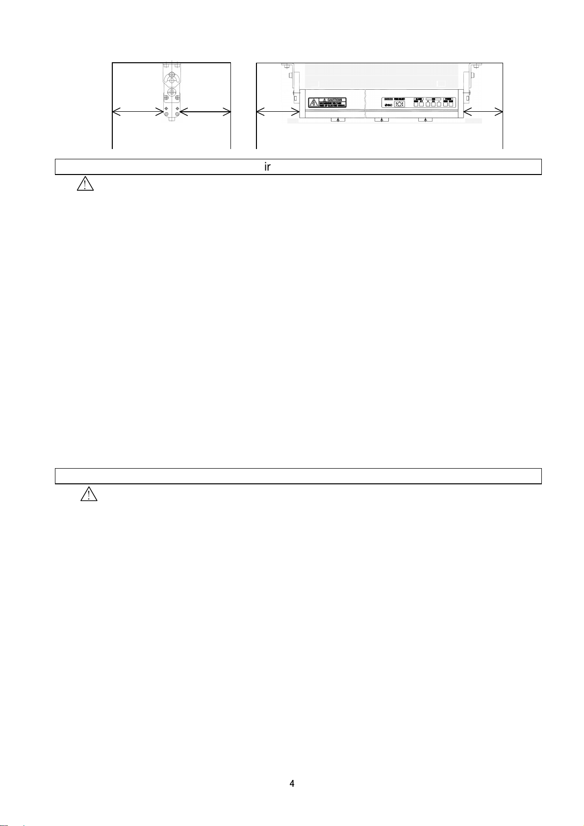
1. Install IZS30 series with keeping distance from the wall etc. as shown in the figure below.
The generated ion might not reach the target effectively and efficiency decrease, where there is wall
etc. inside the area shown in the figure below.
Selection
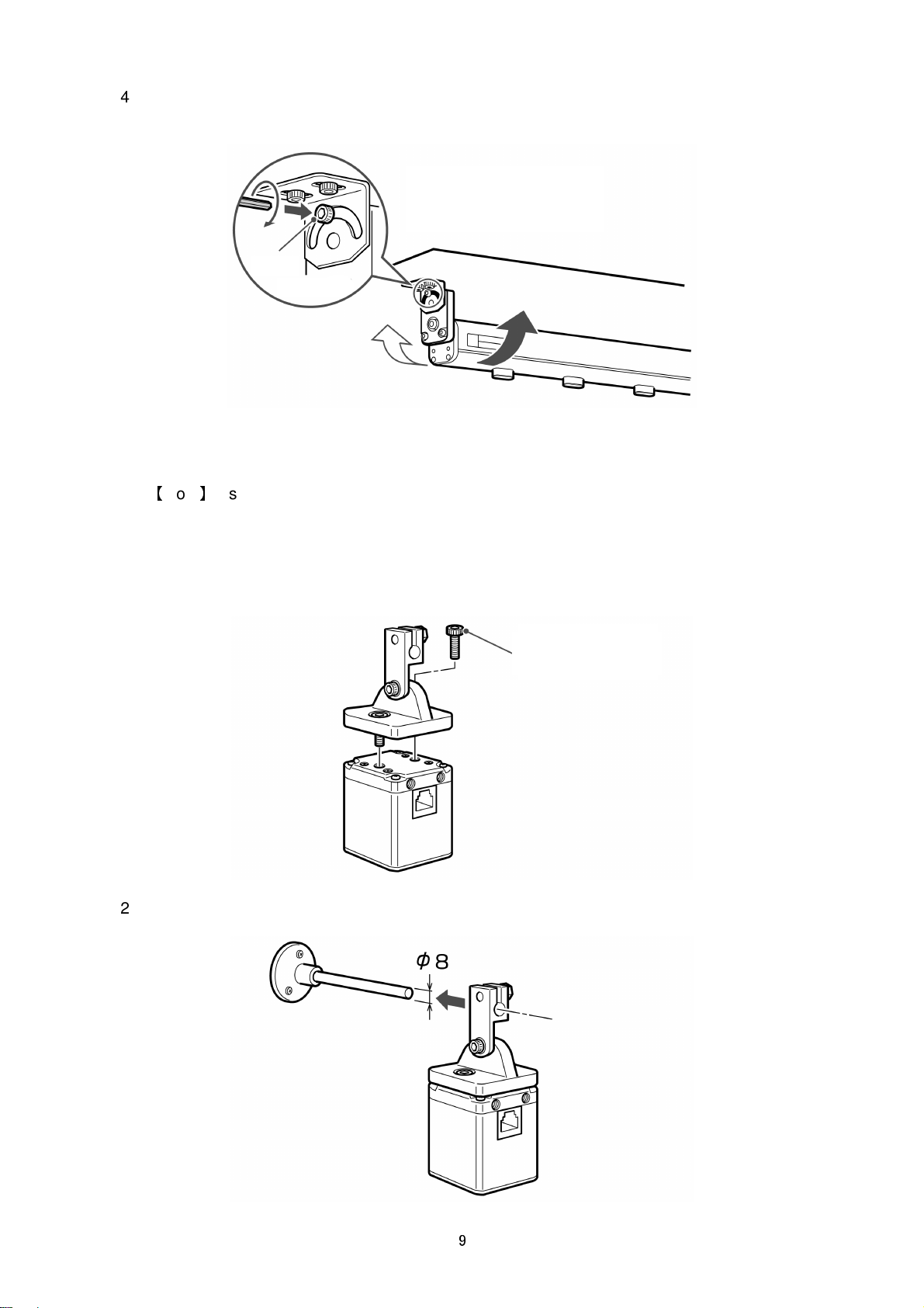
Installation