manuals.online logo
Brands
  1. Home
  2. •
  3. Brands
  4. •
  5. LOADMASTER
  6. •
  7. Truck
  8. •
  9. LOADMASTER EXCEL Series Operating instructions

LOADMASTER EXCEL Series Operating instructions

800−433−2768
[email protected]
100 west eleventh avenue
Norway, M ch gan 49870−0186
po box 186
tel 906−563−9226 tel
fax 906−563−9800 fax
LOADMASTER
….Your Waste Equipment Partner
EXCEL SERIES
Maintenance & Repair Manual
General Body & Hydraulics
General Body & HydraulicsGeneral Body & Hydraulics
General Body & Hydraulics
Released June28, 2007
This manual is publication 7700043
TABLE OF CONTENTS Excel
Maintenance & Repair…general
“body and “Hydraulics
Hydraulics Manual…w/ Hydraulics
Repair
Schematics…Hydraulics & Electrical
Nomenclature “LoadMaster lingo
Pgs a & b
Section 01 Hydraulics… how the system works
Sec01-pg01 thru sec01-pg08
Section 02 Hydraulics…Checking & Adjusting
the various Hydrau settings
Sec02-pg01 thru sec02-pg08
Section 03
Trouble shooting…
Sec 03-pg01 thru sec03-pg04
Section 04 Repairs (various)
Sec 04-pg01 thru sec04-pg08
Section 05 Schematics…
Hydraulics
Sec05-pg01 thru sec05-pg02
Section 06 Schematics…
Electircal
Sec06-pg01 thru sec06-pg04
June 2007
This is the Maintenance/ Repair manual for the
“Excel”.
It includes eneral body Maintenance & Repair
AND is the Hydraulics Manual as well.
The information contained in this Manual
applies ONLY to the EXCEL.
See other manuals for other LOADMASTER
products.
For the Excel Product…
There are 3 manuals for a complete set:
1- the OPERATOR’S MANUAL with Preventive
Maintenance Manual…which also includes
some schematics.
2- The Parts Manual
3- This Maintenance & Repair Manual
Which includes the Hydraulics
800-433-2768
EXCEL
{page date 06-19-07}
Some NOMENCLATURE…the “words” Loadmaster uses…l ngo to “talk”
The Hopper
Throttle-Advance Limit Switch
Upper Light Pod
“Tailgate
-
Mounted Valve”
The bod ’s Face
Ejector Blade
Under sill
“light
bar
Sweep
Blade
Hopper Sill
Riding S
tep
G
ate lift
c linders
Telescopic C linder
Slider
Blade
The “Chassis”
The “T
ailgate”
or
just “Gate”
The “bod ”
“Bod -Mounted Valve”
Main Wrist Pivot
Sweep C linder
C linder
’s Rod
Slider Shoes
Slider c linder
Slider Shoes
Slider Track
800-433-2768
EXCEL
{page date 06-19-07}
Some NOMENCLATURE…the “words” Loadmaster uses
Mud Flap
Gate’s main “Hinge”
Ladder rung
TurnB
uckle
Gate Ajar Switch
Knobbed Lever
s
Tail-side Controls
Bod Access Door
“Decals”
Gate
-
Ajar Lite
(red)
“Bod
-
Mount”
“Button” Switches
“PTO-Engaged” LIte (red)
Return Filter Lite (amber)
Pressure Filt
er
(opt)
Lite (blue)
Gate Lift
C linder
Section 01
rel june 28, 2007
HOW IT WORKS..THE HYDRAULICS
This section of the manual is an overview of the various
individual hydraulic components and how they all work
together as a “system” Reading this section will have
value to you because it will increase your overall
understanding of “how your EXCEL works”, which will
increase your problem solving skills and speed up any
troubleshooting
The components…
Most EXCEL’s are equipped with a
CHELSEA
PTO
When the PTO is engaged on, the pump
will begin to rotate The PTO may have a drive ratio of
1:1 3 (ratio may vary per
specifc
chassis) This means if
the diesel is rotating at 1200 RPM, the pump itself will
be rotating at 1530 RPM The EXCEL pump is typically a
COMMERCIAL INTERTECH P365 SERIES This is a
modern "journal bearing” gear pump that handles higher
speeds and pressures well Since it is a simple gear
pump, any time the pump is rotating it will create flow in
proportion to its rotational speed (RPM) The EXCEL
uses a 6 4 cubic inch per revolution pump The circuit
therefore is about a 42 GPM flow at a
diesel
speed of
1200 RPM
The
body-mounted valve
is a 2-spool GRESEN V20 The
lowermost cover is the
inlet cover
The inlet cover is
closest to the pump and directly connects to the pump
by the
pump pressure hose
The inlet cover holds the
main relief
and has a
gauge stem
from which all of your
pressure gauge readings will be recorded The EXCEL’S
main relief setting is 2900-2950 psi @ throttle advanced
The inlet cover also connects the
auxiliary return hose
to
tank This auxiliary return provides a path to tank for the
body-mtd valve’s functions, since the outlet of the body-
mtd valve has a
power beyond sleeve
that allows
pressurized fluid to be available downstream to the
tailgate-mounted valve
The first spool section is the
tailgate section,
which is a
single-acting (tailgate is powered up and gravity down)
spool in the case of the EXCEL This work section has
no
port devices installed (such as a port relief;
no
port
reliefs used in tailgate section)
The second spool section (highest from body floor) is
the
ejector section
which known as double acting The
ejector
telescopic
cylinder’s
extend (base-side) workport
has a fixed port relief set at 2400psi (“crack flow”)
This
relief will relieve (@2400 psi) during route compaction
only during the telescopic’s smallest stage (aka,
“plunger” stage…the
first
stage to drift closed during the
ejector’s on-route “automatic drift” (towards the cab)
[Sec01-pg01]
The EXCEL uses a valve called the
synkpak
valve to
control the ejector blade/tellescopic cylinder’s
automatic
drift forward (towards the cab) on the route See the
very next topic labeled “EXCEL SYNKPAK” for a detailed
description of how the Synkpak works
The final section of the body-mounted valve is the
outlet
cover
The
power beyond sleeve
is mounted into the
outlet cover
of the body-mounted valve The
PB sleeve
allows for feeding of pressurized fluid
downstream…through the
roof tubing
and to the
tailgate-mounted valve
The
tailgate-mounted valve
controls the blade actions
and most of the optional equipment, such as a roof
mounted “reever” or the “kick bar” It is a PARKER
VG35 valve that usually has 3 or more working sections
and hangs from the tailgate’s roof (The sections with
the “spools” are called “work sections” )
The first section of the tailgate-mounted valve is the
inlet cover
This inlet receives the flow from the roof
mounted pressure tube It also is the origin of the
return
line
since the cover on the other side is a plugged
turnaround outlet cover
The next sections are the option work sections such as
the “2-10 reever” and the “kickbar” Work sections have
“spools” which are spring centered and are manually
shifted in or out to direct flow to a desired function
Typically there are no workport devices used for options
on the EXCEL (see Kart Dumper exception later)
The
blade
section closest to the pump is the
sweep
blade work section
, and it always comes next, (which is
“upstream” of the slider blade work section) This
spooled section has a
knockout positioner
This knockout
postioner is a device that is controlled by one pressure
“’trip” setting for both directions of spool shift When the
spool is manually shifted, the KO mechanically
holds
the
spool shifted until the next time the pressure
rises
to its
setting, whereupon it releases the spool and the spool
knocks-out to centered-neutral position This pressure
rise typically occurs when the cylinders “bottom-out”
This sweep section has a port relief mounted to the
sweep cylinders
base-side, known as the
secondary port
relief
This secondary port relief can allow the sweep
blade to “unwrap” a little if the pressure induced should
exceed “critical” structural loads This important port
relief protects the structure from
excessively
high loads
that could otherwise cause structural damage or
componentry damage
Opposite the
secondary port relief
(at the opposite work
port) is an
anticavitation check
that allows some
“makeup oil” to go into sweep’s rod-side during this
slight blade unwrap Whenever the secondary port relief
is actually relieving, this anticavitation check precludes
powerful suction effects that could extrude the sweep
cylinder’s piston seals
The last working section (the one with the
throttle
advance switch
trigger) is the
slider blade section
This
slider blade section has no port mounted devices The
slider section also has a
knockout positioner
directly
coupled to one end of its spool
The two hopper blade work sections have an internal
flow path known as “tandem center” When a V40’s
tandem center spool section is shifted to do a function,
it blocks the valve’s power core on the
downstream side
This characteristic is important in terms of proper blade
sequence
Since the start of the first half and second
half of the semi-automatic blade cycle is the
“simultaneous” shifting of
both
blade spools, the
sweep
blade
will always move first since its spool is
tandem
center
and it is
upstream
(closest to pump)
of the slide
blade spool
The last section of the tailgate-mounted valve is the
outlet cover
In the case of the EXCEL, this cover’s outlet
port is actually plugged but this section is casted to be a
turnaround
cover The actual return hose is then
connected to an outlet port of the
inlet cover
Leaving the tailgate-mounted valve, the oil flows
through the
roof return tube
to the
return filter
The return filter is a 5-micron (MICROGLAS) with a 25
PSI bypass valve It is a in-tank element and has a
condition
indicator
affixed to the head casting
The
hydraulic reservoir
if fully dressed with a
level gauge
with thermometer, magnet type drain plug, filler/media
breather,
and
cleanout cover
The suction side of the tank has a 100 mesh replaceable
suction filter
It has a 3-PSI bypass valve built into it
The tank has a baffle that separates the suction side
from the return side to promote settling of dirt and
entrained air
The open loop…
When no functions are being
performed (all valve spools in their centered, neutral
position); the oil flow follows a path known as the “open
loop” It originates at the oil tank’s
suction line filter
,
through the
suction hose
, to the
pump
, through the
pump
pressure hose
, to the
body-mounted valve
, up the
roof tube pressure
, to the
tailgate-mounted valve
, back
through the
roof return tube
, through the
return line
filter
and back at the
tank
again As long as none of the
spools are shifted, the oil will flow in this simple open
loop
[Sec01-pg02]
The t ilg te up/down function…
The EXCEL’s
tailgate is power-up and gravity-down (known as
“single-acting”) The lowermost spool section of the
body-mounted valve is the “tailgate” section and is
plumbed to the tailgate lift cylinders
When the hand lever is pulled
outward
the spool itself
also moves outward and the pump’s output flow is
connected to the gate cylinders “up” port (which is the
“base-end” cylinder port) At this very same moment,
the same spool will also connect the “rod-side” ports to
tank So the gate will “raise” If the hand lever labeled
tailgate is pushed
inward
, the tailgate cylinder will
connect to tank and the gate will lower by the force of
gravity
Since the tailgate spool section has no
port
relief at all,
its
only
pressure-limiting device is the main relief of the
body-mounted valve
The tailgate cylinders have orifice restrictors built into
each port (at the cylinder itself) This purposeful
restriction precludes the tailgate from “over-running” the
pump flow when lowering the gate, allowing the gate to
lower smoothly
Never st nd or cross underne th r ised
t ilg te!! T ilg te m y unexpectedly nd
suddenly f ll c using serious injury or de th.
The auxiliary return hose provides the return path to
tank during tailgate raising or lowering
The ejector function…
The
telescopic cylinder
actuates the ejector blade The upper work section of
the body-mounted valve controls the ejector’s telescopic
When the telescopic is fully
extended,
the ejector blade
is fully rearward, towards the tailgate The ejector blade
does two jobs When the tailgate is fully raised at the
landfill or transfer station, the ejector blade is used to
“push-out” the payload This job requires the telescopic
cylinder have available 2000 PSI @ throttle advanced
When the EXCEL is on the route (tailgate fully lowered
and latched, of course), the ejector blade starts parked
at rear of body and then slowly automatically drifts
forward (towards cab) as the garbage is collected and
the payload builds This
drift
will occur automatically as
a pressure head is continuously maintained at the
extend
side of the telescopic This second
on-route
job is
to provide a resisting, yet drifting, front surface for the
hopper blades to compress garbage against This
resistance is created by hydraulic pressure on the
extend-side of telescopic as the telescopic
retracts
toward the cab (blade drifts forward towards the cab)
This head of pressure is controlled by the action of the
synkpak
valve (see next subject, labeled EXCEL
SYNKPAK for description of how it works)
[Sec01-pg03]
The compact blades function…
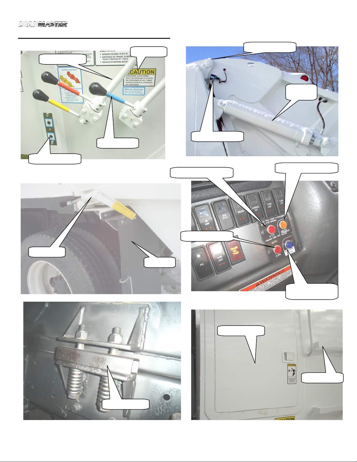
Two of the
tailgate-
mounted valve’s
working sections controls the two
compaction blades The blade that pivots (rotates) is
called the
sweep blade
The blade that slides in the track
channels is the
slide blade
If the tailgate-mounted valve
has more than two working sections (the sections with
moveable “spools”), the extra work sections are for the
“optional equipment” Work sections for the “options”
are always “in front” (upstream; closest to the pump) of
the blades work sections
The sweep blade’s work section is always upstream of
the slider blade’s work section These two blade sections
have a casted flow path known as
tandem center
A V40
“tandem center” work section has the “power core”
internally blocked
downstream
…this means that the
shifted spool
closest to the pump
(the upstream sweep
section) will consume
all
of the available pump flow with
any downstream spools that are also shifted (the slider
spool) getting no flow
until
the upstream section (the
sweep)
shifts back to neutral
This creates a simple function “sequencing” effect Since
the correct operator’s method of cycling the blades is to
shift and release
both
spools’ hand levers
simultaneously, the sweep blade rotates (sweeps)
first
while the slide blade sits motionless waiting for the
sweep’s spool to knock-out to neutral At the very
moment the sweep’s spool automatically shifts to
neutral, all of the pump’s flow is then directed to the
slider blade’s cylinders and the slider blade begins to
move
As mentioned earlier, both the sweep and the slider
work sections have knock-out positioners These
knockouts, when teamed with the plumbing scheme and
the “tandem” center section castings, provide for the
sequencing of the semi-automatic cycling of the
compaction blades The blades must
both
sequence in
their specific order and they must move distinct and
separate of each other to be functioning normally
The knockout positioner is the device that holds the
blade spools shifted until the hydraulic pressure in that
particular section
rises
to the knockouts
pressure
setting
When this setting is reached, the spool is
released and it shifts to neutral (spool centered)
position The pressure setting specification for the
EXCEL is…sweep knockout spec is 2200 PSI @ throttle
advanced and the slider knockout spec is 2700 PSI @
throttle advanced The pressure
rise
typically occurs
when each pair of cylinders bottom-out at the end of
their stroke
Having said all of this, the compact blades do a semi-
automatic compaction cycle as follows…The cycle begins
with both spools (via hand levers linkage controls)
manually simultaneously shifted outward and released
Both knockout positioners grab and hold the spools
shifted The
sweep
cylinders begin to move first with all
of the pump’s flow going to the sweep cylinders (The
sweep’s valve section is closest to the pump and its
internal casted passages are “tandem-center”, which
means all of the pump oil goes to its own workport and
nothing goes downstream ) The sweep blade continues
to rotate until its cylinders complete their stroke and
they bottom-out This bottoming-out causes a rapid rise
in sweep pressure and the sweep knockout will knockout
the sweep spool to
neutral
centered
Meanwhile, the
slider spool has been held shifted with no pump flow
available to it At the very moment the sweep spool
knocks-out to neutral, all the pump flow is
now
available
to the slider spool which begins directing the flow to the
slider cylinders The slider blade
now
begins to move
and it continues to move until its cylinders bottom-out
and the pressure rises to its setting The slider knockout
then knocks the spool to centered neutral and the first
half
of the semi-automatic blade
cycle
is complete
Both
spools are now at their centered neutral position The
blades are said to be stopped at their cycle
interrupted
position This is correct and normal functioning
The second half of the semi-automatic cycle begins
(after the operator visually assures it is safe to do so)
with both hand control levers being pushed inward
simultaneously The sweep blade again moves first (its
valve section is still upstream of slider, of course) and
the second half of the cycle occurs the same way but in
the opposite direction of the first half
The second ry port relief system…
As mentioned
earlier, the sweep work section has a port relief on the
sweep cylinders extend-side (cylinder’s base-end) and
an anti-cavitation check opposite of it (on the retract-
side; the rod-side) Acting together, these two port
mounted cartridges are a
system
that can relieve the
portion of the structural loads that are above allowable
amounts (This would be seen as a slight
unwrapping
of
the sweep blade when the slider blade is nearly all the
way up) In some applications this situation will rarely
occur and in others it may sometimes occur when the
EXCEL body is near its full capacity
The EXCEL sweep’s secondary port relief is set to 3800
PSI @ “crack” (Crack being 2 GPM)
When the slider blade is travelling upward (“compacting”
the garbage), the sweep blade has already been fully
rotated down to “capture” the hopper’s garbage and the
sweep worksection will be in its centered neutral
position The compacting action of the slider blade
travelling upward will necessarily
induce
a hydraulic
pressure on the sweep cylinders base-side The
only
relief located to relieve the excessive
portion
of this
induced load is the relief on the cylinder
ports
side…the
secondary port relief (This is because the sweep spool
is in its centered neutral position and the spool itself
[Sec01-pg04]
blocks
any inlet cover mounted relief from “seeing” the
induced pressure on the work port side)
The anti-cavitation check simply allows for oil to be
drawn into the sweep cylinder rod-side
during
any port
relieving that may occur This prevents any powerful
suction
effect from damaging cylinder seals
This secondary port relief
system
prevents expensive
component and structural failures by preventing blade
loads and pressures from exceeding allowable values
LOADMASTER uses a fixed, non-adjustable secondary
port relief that is set to the
correct
value for the EXCEL
Do not shim djust ny of LOADMASTER’s non-
djust ble reliefs.
[Sec01-pg05]
The optional equipment
… Most EXCEL’S will have an
optional attachment or two The option work-sections
are in the tailgate-mounted valve just upstream of the
hopper blades worksections
These option work sections are simple manually shifted
spools that must be held shifted for their function to
occur The “kickbar option”, the “2-10 reever”, or
“winch” may be installed options They are always
double-acting and the work sections may or maynot
have port reliefs/orifices See separate “chart”
Some options require
orifices
to be installed at the
tailgate-mounted valves option work sections’ work ports
(both ports) to reduce the flow This list identifies which
options use work port restricting orifices:
Kart dumper(s) yes
1-2 option yes
kickbar yes
drum winch no
2-10 reever no
Option l Regener tion…
The “regen” valve is a
available
option
that reduces the hopper blades’ “total
cycle time” It increases the
slider
blade speed in the
downward
(non-packing) direction only The schematic
below is the EXCEL hydraulic circuit with the regen valve
installed
Whenever the EXCEL is equipped with the
regeneration
option…the total hopper blade cycle time can not be
allowed to be less than 22-23 seconds For
example…if you “stopwatch” the total blade cycle time
to be, say, 19 seconds…it is
too f st
and the diesel’s
throttle advance must be reprogrammed to a
lessor
RPM
until the total cycle time is 22-23 seconds (a
slower
speed of blade movement)!
See SEC05 for how to “stopwatch”
Option l k rt dumper(s)…
If the EXCEL is equipped
with kart dumpers, one scheme to supply the hydraulic
oil, is to use one of the tailgate-mounted valve’s option
work sections to control the kart dumper There will be
in-line adjustable orifices installed at both work ports of
the “CT worksection” to control the up/down speed of
the kart dumper function
In the case of the EXCEL, there will also be work-port
reliefs installed for the kart dumper option
Cart-tipper up direction=1800 PSI @ crack flow
Cart-tipper down direction=700 PSI @ crack flow
These “port” reliefs are necessary to assure that kart
dumper operation does not interfere with functioning of
the SYNKPAK valve (which could cause poor
payload/densification performance)
The orifice size Loadmaster uses in most cases (for options) is 7/64”
diameter drill size
[Sec01-pg06]
EXCEL SYNKPAK
revision 10-03-02
On the route, the EXCEL’s ejector blade must slowly and
automatically
drift forward (towards vehicle cab) in a
controlled, pressured fashion to generate good payloads
(good garbage densification)
The EXCEL has a valve that controls the ejector blades
forward “drift” as garbage is collected and compressed
against the ejector blade on the route This valve is
called the “synkpak” valve
This valve
synchronizes
the slow drifting action of the
ejector blade to the
pack
pressure levels occuring at the
hopper blades (specifically, the slider blade) The
“settings” of this valve are
one
important factor in the
EXCEL’S overall payload generation performance
The synkpak valve consists of
two
sequence valves , in
series, built into a aluminum body Both sequence valves
are adjustable (It is located at the front body face about
2 feet above the “body-mounted valve”…a valve “block”
mtd to a bracket) The sequence valves are “cartridge”
style, meaning they can be readily unscrewed as a
whole
pre-set
unit from the manifold body without
needing to tamper with the plumbing connections
Each sequence valve has a controlling pilot hose…
The upper (physically highest in the manifold
body) sequence valve is plumbed to the slider blades
“pack” port and is labelled “C” (C=carriage; also called
“slider” blade)
The lower (closest to the ground) sequence
valve is plumbed to the pump discharge
port…sometimes simply called the “pump pressure”
hose Perhaps strangely, this sequence valve is labelled
“B”…remember Bump=pump
The sequence valve cartridges are BOTH set to the same
SETTING of…
C (CARRIAGE) = 2500 PSI
B (PUMP) = 2500 PSI
The synkpak’s body is plumbed between the ejector’s
extend port and the tank The port marked “CYL”
connects to the ejector’s tellescopics extend port The
port marked “T” connects directly to tank Review the
schematics Since the body-mounted valves spool
section for the ejector is in its’ centered, neutral position
(when on-route, collecting garbage), it’s work ports are
blocked
Therefore, the synkpak
controls
the only
available path to tank and thusly controls the ejector’s
telescopic on-route collapse (drift towards cab)
Whenever the
pilot pressure
at a sequence cartridge is
less than that sequence cartridge’s
setting
…the
sequence cartridge will block the to-tank path
Whenever the
pilot pressure
at a sequence cartridge is
greater than that cartridge’s
setting
…the cartridge
opens
As mentioned earlier, the two sequence cartridges are in
series
Therefore
both
sequence cartridges must be
piloted open before the ejector’s tellecopic has a path to
tank and can collapse (retract) This means that both
pilot pressures must rise to the set trip points
simultaneously
Both pilots have guage coupling nipples installed The
“C” (carriage; aka slider) nipple is screwed directly onto
the synkpak valve and the “B” guage nipple is located at
the body-mounted valve’s inlet cover A third guage
nipple is located at the tellescopic’s extend port See
schematic
A orificed fitting is installed directly into the synkpak’s
“cyl” port (5/64” dia) When both sequence cartridges
have opened, the path to tank is opened and the
telescopic will suddenly retract (collapse) just enough to
relieve
some
of the force in the garbage bale
The garbage bale can be thought of as a giant spring
that
must be released
just a bit to allow the hopper
compaction blades to be able to clear the loading
hopper This orifice assures that this oil release to tank,
through the now open synkpak valve, occurs in small
controlled amounts The orifice is therefore important to
good payload performance (good garbage densification)
ADJUSTING THE SYNKPAK VALVE
The
only
reason to attempt to adjust the synkpak valve
is if your payload performance has been determined to
be below normal or the ejector blade is not
“autodrifting” Read the OPERATION & MAINTENANCE
manual topics related to “generating payload”
before
you attempt to adjust the synkpak Check and
adjust all
the other settings
before approaching the synkpak valve
The most important thing to remember is to
not
adjust
the synkpak valve until after you have checked these
other system settings (which are, in effect, “timed” to
the synkpak’s settings…
Check the system m in relief to be 2900-2950 psi at
throttle advanced (EXCEL spec)
Check the slider knockout to be at 2700-2750 psi at
throttle advanced (EXCEL spec)
Replace the sweep port relief to be 3800psi crack (
if
excessive sweep blade unwrap occuring) (p/n 8800605)
Now run the unit for a week or two while monitoring the scale
weights of the true
full
loads and confirm “good” payload
performance
[Sec01-pg07]
If the payload still seems to be below normal, only then
turn your attention to the synkpak valve
To dial in your two synkpak settings would require
monitoring 3 pressure gauges
while the unit is on the
actual route
and body nearly full of garbage Since this
is highly dangerous (be aware vehicle runovers and
traffic related accidents are serious refuse truck
accidents), LOADMASTER does not recommend this
method Trained personnel only should perform this type
of monitoring
After you have checked all of the other relevant,
payload generation factors…use the simple turn-of-the
–screw method to reset the synkpak valve Turn both
synkpak adjusters inward 1/8 TURN Then place the
truck back in service and monitor loads for another week
or two Turning
both
synkpak adjusters inward ( loosen
jamb nuts and remember to re-jamb) increases the
resistance of ejector blade and therefore will increase
your payload density Always turn the two adjustments
in unison…if you turn c inward 1/8 turn, then turn b
inward 1/8 turn (exactly)…unison
If after monitoring/weighing several true,
full
(not
partial) loads and the payload performance is still not
acceptable, you can make another 1/8 TURN “in” and
repeat the weighing of true,
full
loads (not partial loads)
This is ¼ total turns inward If payload performance is
then still
not
corrected, call LOADMASTER and order the
two cartridges from LOADMASTER in new, benchset
condition Replace the c and b cartridges
correctly…remember the cartridges will look the same
but have different settings that you will not have to
touch
The synkpak valve’s two adjusters are fairly
sensitive
…small 1/8 turns of adjuster can make big
changes in payload generation and ejector blade
behavior Do not overadjust If you dial-up too much
ejector drift resistance, the ejector will not
automatically
drift forward towards the cab This is a functional
defect…the ejector must drift automatically (If the
operator is “manually” moving the ejector blade forward,
the EXCEL will not achieve good payload performance )
Tip…after you have loosened one of the jamb nuts…get a
mental picture
of what 1/8 turn will look like
before
you
actually do your turning…once you become confused, you will
become “lost” and can not get back to where you were Do
this adjustment thoughtfully and carefully
Immediately
after
you adjusted the first cartridge, do the second exactly the
same way This can not be stressed enough…think about it
before doing it After inserting allen wrench in adjuster, use a
magic marker to create a “reference” line on valve body which
is aligned with the allen wrench…then “turn”
exact
amount
Reminder…always adjust
both
adjusters exactly the
same amount
If you become “lost”, acquire fresh
pre-set
cartridges
from LOADMASTER Then remember to install in proper
positions the settings are different Save your old
cartridges, they could be reset on the bench
W rning!!!
BEFORE ENTERING THE BODY, ALWAYS SHUTDOWN THE
DIESEL, PLACE THE IGNITION KEYS IN YOUR POCKET AND
ATTACH A SIGN TO THE STEERING WHEEL THAT SAYS “DO
NOT START ENGINE”! PERFORM YOUR SHOP’S DETAILED
LOCKOUT/TAGOUT PROCEDURE. THE EJECTOR BLADE
COULD MOVE UNEXPECTEDLY CAUSING SERIOUS INJURY OR
DEATH.
IF ENTERING THE FORWARD (CAB) SIDE OF EJECTOR,
FIRST
EXTEND THE EJECTOR BLADE ALL THE WAY REARWARD
(TOWARDS TAILGATE) AND “PARK” IT THERE. THEN DO YOUR
COMPLETE LOCKOUT/TAGOUT PROCEDURE.
TIP: a good rule of thumb…if “lost” where adjsuter’s are
at…gently bottom out the adjuster and then “back-out” exactly
1 5/8 Turns…do it to both adjusters…this has proven to be
very close to correct settings for both
Troubleshooting tips…
If the ejector blade will not
automatically
drift forward on the route (a
functional defect)…
1-Inspect the orifice to be clear and free
2-Remove both synpak cartridges and inspect the o-ring seal at the
tip of the cartridge…if erroded seal, the synkpak can not ever open
and ejector blade can not ever auto-drift (Do one cartridge at a
time…do
not
flip-flop the cartridges!) Replace all cartridge seals
3-If both of above are “ok”’,
only then
adjust both synkpak adjusters
outward (ccw) exactly 1/8 turn (or slightly less than 1/8 turn) and then
retest the excel on the route to confirm the return of automatic ejector
drift forward After inserting a allen key in adjuster, make a magic
marker reference mark, on the synkpak’s body, that is aligned with the
allen key…then turn ccw ex cly 1/8 turn (Remember…seemingly very
small adjustments will have large effect on ejector’s drift behaviour )
[Sec01-pg08]
c pilot
c pilotc pilot
c pilot
b pilot
b pilotb pilot
b pilot
c cartridge
c cartridgec cartridge
c cartridge
b cartridge
b cartridgeb cartridge
b cartridge
tank line
tank linetank line
tank line
telly cyl line
telly cyl linetelly cyl line
telly cyl line
orifice
orificeorifice
orifice
OVERVIEW OF CORRECT EXCEL
SPECIFICATIONS…
This page lists the EXCEL specifications needed for
checking and setup These values apply only to the
EXCEL; other LOADMASTER models will have other
specifications Refer to the manual that specifically
applies to that model Alw ys p y ttention to the
diesel RPM specified…if you me sure t some
other diesel RPM, the re ding will
not
be correct!
MAIN SYSTEM RELIEF…
This is located in the inlet cover of the body-mounted
valve The body-mounted valve is the valve just inside
the body access door Take your reading at the gauge
stem provided at the inlet cover of the body-mounted
valve
Spec is 2900 PSI +/-50 PSI @throttle dv nced
SYNKPAK VALVE…
This aluminum-housing valve is mounted at the body’s
forward face about 2’ above the body-mounted valve
This valve controls the ejector blades automatic drifting
forward on-route as payload builds-up in the body It
consists of two sequence valves (in series) each with a
pilot line See schematics and separate write-up for
detailed information Spec is
C-PILOT (SLIDER PACK) 2500PSI
B-PILOT (PUMP PRESSURE) 2500 PSI
These are “cartridge-style” sequence valves that can be
replaced easily with f ctory pre-set cartridges when
needed
SWEEP KNOCK-OUT POSITIONER…
This device is directly coupled to the sweep
worksection’s spool of the tailgate-mounted valve
Spec is 2200 PSI +/-50 PSI @ throttle dv nced
This device is very fast acting and can
not
be measured
with a common glycerin-filled gauge A glycerin filled
gauge will give a reading that is very false
SLIDER KNOCK-OUT POSITIONER…
This device is directly coupled to the slider worksection’s
spool of the tailgate-mounted valve
Spec is 2750 PSI +/- 50 PSI @ throttle dv nced
This device is very fast acting and can
not
be measured
with a common glycerin-filled gauge A glycerin filled
gauge will give a reading that is very false
SECONDARY PORT RELIEF…
This cartridge type port relief is screwed into the
sweep
worksection (on the cylinder’s base-end) of the tailgate-
mounted valve (on cylinder’s base-end…pack side)
Spec is 3800 PSI @ “cr ck” flow
This setting is not adjustable (and do not “shim”)
For more detailed explanations of these specifications,
see the “check and setup” writeup that applies to each
particular specification
THROTTLE ADVANCED RPM… (“T-A”)
This is the
diesel
RPM that the diesel will raise to when
the EXCEL’s electric controls signal the need
Spec is 1150 RPM-1350 RPM (typic lly).
When the diesel speed does advance, it will be
noticeable to the ear and can be read at the cab’s
tachometer
DIESEL IDLING RPM…
This is the diesel RPM with diesel at idle
Spec is per wh tever the diesel m nuf cturer
s ys it is supposed to be; usu lly bout 750 RPM.
EVERY SPECIFICATION IS TO BE MEASURED WITH THE
GAUGE COUPLED AT THE INLET COVER OF THE BODY
–MOUNTED VALVE!
If the readings are taken at some
other spot in the hydraulic circuit, the readings will be in
error
LOADMASTER has installed the male gauge stem for
gauge coupling at the inlet cover of the body-mounted
valve as standard equipment
LOADMASTER has available the 3000 PSI glycerin filled
gauge, 2 feet of hosing, and the matching female
coupler all preassembled (Order LOADMASTER P/N
0130014)
This particular type of coupler requires that the pressure
be low to cleanly couple/uncouple Shut down the
diesel and disengage the PTO when
coupling/uncoupling the gauge to avoid having hydraulic
oil escaping
[Sec01-pg09]
OVERVIEW OF MAJOR EXCEL
COMPONENTRY…
PTO… Varies… a CHELSEA PTO that will allow the pump
to be direct coupled to the PTO Drive ratio is typically
near 1:1 3, which is to say a 30% speed increaser The
specific part number will vary depending on the type of
chassis transmission, rotation required, etc Will be
OMFB manufacture PTO if unit equipped with “Piston-
Pump”
PUMP…Usually a COMMMERCIAL-INTERTECH P350 in a
6 4 cubic inch per revolution displacement The specific
part number will vary depending on the rotational
direction needed Will be OMFB brand if “Piston-pump”
BODY-MOUNTED VALVE…A GRESEN V20 SERIES
configured to LOADMASTER’s specification This valve
always has 2 spooled work sections One worksection
controls the tailgate cylinders and the other worksection
controls the ejectors telescopic
TAILGATE-MOUNTED VALVE…A PARKER VG35
SERIES (april2004) configured to LOADMASTER’s
specification This valve has usually has 3-4 work
sections Closet to the pump will be any “option”
worksection(s), followed by the sweep worksection, and
lastly the slider worksection The sweep and the slider
worksections have devices called knockout positioners
directly coupled to their spools
RETURN LINE FILTER… A INTERNORMAN 5 micron
(nominal), tank-top filter with synthetic “microglass”
element and a condition indicator gauge
OIL RESERVOIR…In-the-body 42 gallon capacity tank
with magnetic type drain plug, fill level gauge with
thermometer, top surface clean-out cover, combo
screened filler/breather, and a full port ball valve at
suction line Inside the tank, near the bottom, is a 100
mesh suction line strainer
TELESCOPIC CYLINDER…The ejector blade is
actuated by a HYCO telescopic cylinder It is built to a
LOADMASTER dimensional specification for to suit the
EXCEL When the telescopic is fully extended, the
ejector blade is fully rearward, towards the tailgate
SWEEP CYLINDERS…A pair of rod-type hydraulic
cylinders The EXCEL uses a 5” bore x 23-5/8” stroke
with a 3” rod diameter These are internally cushioned
to reduce end of stroke pounding Premium quality
design and manufacture by PETTIBONE All of the
EXCEL’s various cylinders have zero-leak o-ring boss
ports and feature chrome plated rodding
SLIDER CYLINDERS… A pair of rod-type hydraulic
cylinders The EXCEL uses a 5” bore x 43” stroke with a
2-1/2” rod diameter These are internally cushioned to
reduce end of stroke pounding Premium quality design
and manufacture by PETTIBONE
TAILGATE CYLINDERS… A pair of rod-type hydraulic
cylinders The EXCEL uses a 4-1/2” bore x 30-1/8”
stroke with a 3-3/4” rod diameter These cylinders are
single-acting since the EXCEL has a gravity lowered
tailgate These have integral,port-mounted orifices
IN-CAB ROCKER SWITCH PANEL…The various
switched electrical circuits will have their “inside the cab”
switches grouped together here A switch is “on”
(closed) if the red color band is visible This switch panel
is typically located just to the left of the steering wheel
FUSE BLOCK…All of the various branch circuits
originate at this ATO style fuse block which is typically
located nearly under the dash in a protected location
near the operator’s left foot
IN-CAB RELAYS…Some EXCEL’s require relays to
control the “throttle advance” or other functions The
exact number of relays on any particular EXCEL is
dependent upon factors that include the particular
chassis used LOADMASTER uses IDEC brand quality
relays These relays are the yellowish, transparent “ice
cube” relays that are typically located in a protected
“inside-the-cab” spot usually somewhere near the
driver’s left foot
FIREWALL TERM STRIP…Every EXCEL has a term
strip mounted to the firewall located “under the hood”
ahead of the driver’s side The color-coded, labeled
wires “pass through” this strip LOADMASTER includes
this as a “troubleshooting” feature to speed up finding
the source of an electrical circuit malfunction
HARNESSES…The electrical wires are bundled, labeled,
colorized, and protectively covered in a “harness” The
overall electrical harnessing is made up of several
independent
subharnesses
connected together at
strategic locations with premium quality DEUTSCH
metallic body multi-pin connectors
LIMIT SWITCHES…The throttle advance limit switch
and the tailgate ajar switch is the same switch The
throttle advance switch is wired N 0 (and closes
whenever the slider spool is shifted out of neutral) and
the tailgate ajar switch is wired N C (and is held open by
a lowered tailgate) This switch is a MICROSWITCH
brand wobble stick with sealed body A cable connector
seals the cable as it enters the switch
BUTTON SWITCHES…The “buzzer signal” and
“throttle” advance switches are fully encapsulated and
mounted to a stainless steel panel with a stainless
unpainted
grounding post Has a “click” feel when it
switches
[Sec01-pg10]
Section 02 Checks and Setups
CHECK and SETUP… BLADES
“
CYCLE T ME”
rel June 2007
“CYCLE TIME” IS THE TOTAL NUMBER OF SECONDS IT
TAKES THE SLIDE AND SWEE BLADES TO COM LETE
ONE ACK CYCLE, WHILE THE DIESEL IS AT ADVANCED
THROTTLE R M.
The EXCEL specification is 26-27seconds without
optional regeneration and with the diesel’s RPM
advanced to 1150-1350 RPM. (The specific diesel
rpm will vary with pump/pto options.) The
hopper blade cycle time W TH OPT ONAL
REGENERAT ON specification is 21-23 seconds.
One complete pack cycle is to start with both blades at
“home” position and end up also at “home” position.
Checking Procedure:
1- Both the slider and sweep blades are parked in
“home” position.
2- Diesel running; Transmission in neutral; ark Brake
is applied on; TO is engaged on; Throttle Rocker
switch is on (red band will show)…
3- This is a two person task. One person with a stop
watch and one person manning the blade’s hand
control levers.
4- ull both control levers outward simultaneously
(and release them) as stop watch is triggered on
spoken “go”.
5- The person manning the controls must be in a state
of ready to “push in” (and release) the hand control
levers at the very instant that both levers are seen
to kick-out to neutral. (This is the “interrupted” or
half-way point of the automatic cycle.) This
interruption must be kept as brief as practical to
correctly measure the “cycle time”. Meanwhile, the
stop watch has continued to run.
6- Now the stop-watch holding person must be alert to
stop the watch at the exact moment the blades are
both back to home position (both hand levers will
have “kicked-out” to neutral).
7- Record this number of seconds and repeat the time
measuring process a total of three times for best
confidence of accurate measurement.
STAY CLEAR OF MOV NG HOPPER BLADES AND THE HOPPER
LOAD NG S LL WHEN BLADES ARE MOV NG! F YOU OR A
WORK PARTNER S CAUGHT N THE BLADE ACT ON, SER OUS
NJURY OR DEATH W LL RESULT.
To adjust the cycle time, alter the diesel’s throttle
advanced R M setting.
Do not adjust outside the
previously specified range….damage to componentry
may occur.
Most diesels today are “E-DIESELS”. You will most likely
need to schedule a visit to your local chassis dealer since
the
advanced throttle R M
is a programmed setting and
will require a programming device that you will most
likely not posses.
If you do adjust the diesel’s advanced throttle to 1300-
1350 R M (maximum allowable EXCEL R M) and the
measured “cycle time” is still “slow”, see troubleshooting
section for identifying and remedying other causes of
“too slow” blade movements.
REGENERAT ON OPT ON AND CYCLE T ME
If your EXCEL is equipped with the
optional
regeneration
valve…the correct hopper blades
total cycle time
will be
21-23 seconds (excel specification).
The regeneration valve will “speed up” the movement of
the slider blade during slider blade
downward
travel
(only). (The regeneration valve does
not
affect the
speed of any other blade movement.)
If your EXCEL has regeneration, the diesel’s throttle-
advanced setting must be programmed to assure that
the hopper blades total cycle time
does not exceed
the
22-23 seconds! This may require programming the
diesel throttle advance parameter to a value as low as
1150 rpm.
Never allow the EXCEL to operate with a hopper
blades
total cycle time
at value less than the 21-
22 seconds (which is to say…”faster” blade
movements).
For example, if you stopwatch the
EXCEL
and it
times to 19-20 seconds (too “fast”)…then you must
immediately have the diesel’s throttle advanced setting
reprogrammed to a lower R M value that results in a
timing of 22 to 23 seconds.
[Sec02-pg01]
BLADES AT
BLADES ATBLADES AT
BLADES AT
THEIR
THEIRTHEIR
THEIR
HOME POSITION
HOME POSITIONHOME POSITION
HOME POSITION
CHECK and SETUP…THE “MA N
REL EF” OF BODY-MTD VALVE
rev12-01
THE MAXIMUM OVERALL HYDRAULIC SYSTEM
RESSURE IS REGULATED BY THE “MAIN RELIEF”
VALVE, WHICH IS A CARTRIDGE TY E VALVE SCREWED
INTO THE INLET COVER OF THE EXCEL’S BODY-
MOUNTED VALVE.
The EXCEL specification is 2,950 PS +/- 50 PS
@ Throttle Advanced RPM (usually about 1400
rpm).
To check the setting of the system “main relief”, do the
following procedure.
Checking Procedure:
1- Shut down diesel, place the ignition keys in your
pocket and a sign on the steering wheel that says
“DO NOT START”.
2- Connect a 0-3000 SI glycerin filled pressure gauge (on a
¼” hose about 2 feet long) to the body-mtd valve’s gauge
stem that you will find at this valve’s inlet cover. (The
“body mounted valve” is the 2-section stack valve located
just inside the body’s access door). Exit the body and get
your feet back on the ground.
3- Start Diesel running; Transmission in Neutral; ark Brake
is engaged on; Throttle Rocker switch is on; Tailgate fully
down and fully
latched on both
sides…
4- Extend the ejector blade fully rearward (all the way
towards the tailgate) if it isn’t already and leave it there.
5- Depress and hold the nearby
“throttle”
advance button
switch…diesel R M will be heard to raise to the advanced
R M.
6-
Shift “tailgate” hand lever to
“raise”
position (refer to the
decal that is affixed to the body) and hold (soak)…read
the gauge while
still holding throttle advanced
. This is the
“setting” of the main relief valve. Release the hand lever
labeled “tailgate” and then repeat taking a reading for a
second time.
If the main relief setting needs adjustment to be brought
within the above specification, follow this procedure.
Adjustment Procedure:
1- Shutdown diesel, place ignition keys in your pocket
and a place a sign on the steering wheel that says
“DO NOT START”.
2- Open body side access door and enter the body.
3- Remove the acorn nut, which acts as a cover over the
adjuster stem.
4- Loosen (ccw) the jambing nut.
5- Use a hex key to turn the adjuster…start with about 1/8
turn. Turning adjuster inward (cw) will increase the
setting. Turning the adjuster outward (ccw) will decrease
the setting.
6- Tighten jamb nut and install acorn nut cap.
7- Never exceed the LOADMASTER specification. Expensive
component failures and/or structural damage can occur.
Also, if the main relief is set too low, loss of compaction
and/or functional performance can occur.
8- Exit the body (your feet back on the ground) and restart
diesel. Diesel running; Transmission in Neutral; ark Brake
on; TO engaged on; Throttle Rocker switch on…
9- Recheck the main relief’s setting again using previously
listed procedure. It is worth mentioning again that you
must
advance the throttle
to accurately check this relief
setting. If it is within specification, you are done.
Otherwise repeat the checking and adjusting until it is “to
spec”.
TI ….Throughout this manual you will notice that all the pressure
settings are stated at a certain diesel R M speed. It is important that
you check the setting at the stated R M since pump flow is dependent
on diesel’s R M. One “setting” of the main relief will measure
differently @diesel idle (typically about 750 R M) versus @ diesel
throttle advanced (typically about 1400 R M).
BEFORE ENTER NG THE BODY, ALWAYS SHUTDOWN THE
D ESEL, PLACE THE GN T ON KEYS N YOUR POCKET AND
ATTACH A S GN TO THE STEER NG WHEEL THAT SAYS
“DO
NOT START ENG NE”!
PERFORM YOUR SHOP’S DETA LED
LOCKOUT/TAGOUT PROCEDURE. THE EJECTOR BLADE
COULD MOVE UNEXPECTEDLY CAUS NG SER OUS NJURY OR
DEATH.
F ENTER NG THE FORWARD (CAB) BODY S DE OF EJECTOR,
F RST EXTEND THE EJECTOR BLADE ALL THE WAY REARWARD
(TOWARDS TA LGATE) AND “PARK” T THERE. THEN DO YOUR
COMPLETE LOCKOUT/TAGOUT PROCEDURE.
[Sec02-pg02]
0130014
CHECKING AND ADJUSTING THE KNOCK-OUT
POSITIONERS
The EXCEL’s correct knock-out specifications are…
SLIDER 2700-2750 PSI @ THROTTLE ADVANCED
(will advance” automatically during procedure)
SWEEP 2200-2250 PSI @ THROTTLE ADVANCED
(A second person will have to hold depressed a t-
adv button switch for sweep).
The
EXCEL’s
correct system main relief specification is
2900-2950 PSI @ THROTTLE ADVANCED
“CHECKING” WHERE THE
EXCEL’S
SLIDER’S KNOCK-
OUT POSITIONER (”K-O”) IS PRESENTL SET…
This procedure will identify the knockout-positioners present
setting. (See separate procedure below to adjust” a k-o.) You will use
the system main relief’s adjustment feature to identify where the k-o is
set. This relief is located at body-mounted valve’s” inlet.
 1- Move the ejector blade fully rearward (towards tailgate) and
leave it there.
 2- Attach a 0-3000 psi glycerin filled gauge on a 2-foot hose with
the female coupler…to the gauge stem that exists at the body-
mounted valve’s inlet cover. <FIG 1>
 3- Loosen jamb nut at main relief. Arbitrarily turn outward (CCW)
the main system relief 2 to 3 turns to lower its setting a great deal.
<FIG 2>
 4- Diesel running; PTO to engaged; Throttle’s in-cab, master
rocker switch to ON (red band will show)
 5- Go the tailgate; move the orange slider control lever to shifted
position (push for up”) and let go of lever. <FIG 3>
The lever should not knockout to neutral because the main
relief is very low and therefore undercutting the K-O. (Many
people will call this soaking” the relief.) The throttle should
be automatically advancing to 1200-1300RPM.
 6- Go back to the body-mounted valve. Affix your eyes upon the
pressure gauge. Hold the gauge in one-hand so you can clearly
read it…. the slider is still soaking”.
 7- Begin slowly turning upward (cw) the main relief’s hex key
adjuster…slowly and smoothly. All the while, keep your eyes
affixed upon the gauge. Soon you will feel and hear the slider’s
knock-out kick to neutral. Memorize and jot down on paper the
gauge reading that occurred at the very moment it kicked-out.
This is the present slider k-o setting.
 8- Repeat steps 3-7 again…until you have confidence your
reading” is accurate…jot this down on paper
.
[This procedure will also work for checking the sweep’s k-o, but a
second person must hold pressed a throttle-advance button switch.]
Important! Always remember to return the main system re ief to
its correct specification of 2900-2950 PSI @ throttle advanced
when you are finished identifying what the knock-out is set to.
(Set main relief” by locking both tailgate turn buckles and
shifting tailgate raise/lower lever to raise” while holding throttle
advanced. See earlier topic in this manual.)
“RESETTING/ADJUSTING” THE
EXCEL’S
SLIDER’S K-O
POSITIONER
!DANGER! Be sure diesel is not running, ignition keys
are in your pocket, and affix a sign on steering wheel that
reads do not start”… before you enter the hopper or get
near the hopper’s blades!
Repeat these lockout/tag out steps each and every time
you must enter the hopper! (Your shop may have a more
detailed LOCKOUT/TAGOUT procedure. If so, then perform
the detailed LOCKOUT/TAGOUT procedure.)
To make a adjustment (the checking above has shown k.o. to be out
of spec”)…
 1-Remove the small, rubbery hole plug from the end of the K-O
positioner’s bonnet (at the end face of it)…the adjuster” is behind
it <FIG. 4> [Sec 02-pg 03]
 2-Do the checking” procedure (above) to find out where” the K-O
positioner is presently set at. (CONT’D NEXT PAGE)
TOOLS REQUIRED…
5/32” ALLEN WRENCH AND 9/16” OPEN END FOR MAIN RELIEF;
3/32” ALLEN WRENCH FOR K.O. ADJUSTMENT; 3000PSI
GUAGE & HOSE ASSY
Fig.1
Fig. 2
Fig. 3
SLIDER
CHECKING AND ADJUSTING THE KNOCK-OUT
POSITIONERS…CON’TD
 3-The rule of thumb” is…1/4 turn of the k-o’s allen-head adjuster
is roughly equivalent to 100 PSI of setting change.
Based upon where the k-o positioner is presently checked” to be
set at…turn the k-o’s allen head adjuster inward (cw…raising the
pressure setting) or outward (ccw…lowering the pressure setting)
to get closer to the EXCEL specification. <FIG. 5>
EXAMPLE... The correct EXCEL spec for the slider is 2700 psi @
throttle advanced.
Your checking” procedure reveals the slider’s knock-out to be
presently set to 2500 psi @ throttle advanced.
Calculate 2700 minus 2500=200 psi on the low side”…that is ¼
turn x 2= ½ turn total needed.
Turn slider k-o adjuster’s allen-hex inward (cw; the raising”
direction) exactly ½ turn.
(The V40 knock-out adjuster has no jamming
nut…adjustment is held in place by internal friction.)

4-Now repeat the page 1” checking procedure again
(repeating steps 3-7)…jot down where k-o setting is now
set”

5-Continue if need be… using smaller /8 turn or / 6
turns next, until you are dialed” into the correct
specification.
Note : There are two k-o positioners…be sure to first correctly
identify the one you choose to work on. (The slider k-o is the
lowest one, nearest to the hopper’s loading sill; the slider work-
section has the switch trigger on its push-pull rod.)
!DANGER! Be sure diesel is not running, keys
are in your pocket, and affix a sign on steering wheel
that reads do not start”… before you enter the
hopper or get near the hopper’s blades!
Repeat these lockout/tagout steps each and
every time you must enter the
hopper!
(Your
shop may have a more detailed LOCKOUT/TAGOUT
procedure. If so, then perform the detailed
LOCKOUT/TAGOUT procedure.)
[This procedure will also work for adjusting the sweep’s k-o,
but a second person must press and hold a throttle-advance
button switch. Sweep will not have automatic throttle-advance.]
Important! Always remember to return the main system
re ief to its correct specification of 2900-2950 PSI @
throttle advanced when you are finished adjusting the
knock-out setting. (Set main relief” by locking both
tailgates turn-buckles and shifting tailgate raise/lower lever to
raise” while holding throttle advanced.)
Important! Always remember to replace the rubber hole plug
(see parts manual)…Do not allow dirt or water to enter the
knock-out device. Always keep the knock-out sealed” by
installing the rubber hole-plug.
End Knock Out check and adjust
Fig 4
Fig 5
[Sec02-pg04]
CHECK and SETUP…”SECONDARY
PORT REL EF”
THE TAILGATE-MOUNTED VALVE’S SWEE SECTION HAS A
ORT RELIEF INSTALLED ON THE BASE-SIDE OF THE SWEE
CYLINDERS AIR.
THIS “SECONDARY ORT RELIEF” IS SET SIGNIFICANTLY
HIGHER THAN THE OTHER RELIEF SETTINGS AND IS
ROVIDED TO ALLOW FOR SOME RELAXING OF “INDUCED
LOADS” THAT WOULD EXCEED THE CRITCAL ALLLOWABLE
STRUCTURAL LOADS
.
See Table of Contents for a write up of how this particular
hydraulic component functions in the system.
The EXCEL’S specification for this S.P.R. is 3800
PS @ “crack” (with crack being defined as 2
GPM).
Checking Procedure:
Actually, there is no commonly available method to field
“check” where this relief is set. This is because it is “test-stand
set” at its
crack
value of 3800 SI
@ 2 G M
. If you suspect
that this port mounted relief is not correct, it is most practical
to order from LOADMASTER a brand new bench set cartridge.
Fortunately, changing out this cartridge type valve is a
relatively fast operation and the cartridge itself is not
expensive. See the Table of Contents to locate a write-up on
change-out procedure in Repair Section. It is worth repeating
here to pay particular attention to (a) assure a clean valve
cavity (magnet wand and penlight and hooking tools) before
putting in the new cartridge, and (b) the “cartridge tip seals”
rubber 0-ring and plastic backup ring are well doped up with
axle grease when you (slowly & gently & straightly) insert the
new preset cartridge into this
cavity. All the
old junk
must
be purposefully “fished out” of cavity; it does not come
out on its own.
Sometimes it is a nicked or
extruded “tip seal” that is the
real culprit and the cartridge
(and its setting) are actually fine.
A typical “symptom” that might lead you to replace this
cartridge is that the sweep blade is “tending to unwrap” when
the body is nearing its full rated payload capacity. Be careful in
your observations here because some occasional unwrap of
sweep blade is
normal
(such as when the body
really is full
and
the payload is at its rated value).
One worthwhile
check
you can do is to physically trace the
sweep cylinder’s base side hoses to be sure the Secondary ort
Relief is correctly located on the
base-side
(not the
rod-side) of
the sweep’s cylinders.
Adjustment Procedure:
This S. .R. is
not
adjustable; it must be replaced with a totally
new preset and
fixed
cartridge.
Never “shim adjust” this port relief cartridge. Eventually this
could cause expensive structural damage and/or componentry
damage. LOADMASTER warranties are void if this is done.
Replace the entire port relief cartridge with a new
LOADMASTER preset cartridge and always replace the old
seals with new. See EXCEL parts manual.
n the unlikely event that cartridge replacement
does not solve the blade unwrapping symptom,
refer to the Troubleshooting Section of this
manual for other possible causes and remedies.
BEFORE ENTER NG THE LOAD NG HOPPER, ALWAYS
SHUTDOWN THE D ESEL, PLACE THE GNT ON KEYS N YOUR
POCKET AND ATTACH A S GN TO THE STEER NG WHEEL THAT
SAYS “DO NOT START ENG NE”! DO YOUR SHOP’S DETA LED
LOCKOUT/TAGOUT PROCEDURE.
THE BLADES COULD UNEXPECTEDLY AND SUDDENLY BEG N
MOV NG WH CH W LL CAUSE SER OUS NJURY OR DEATH.
CAUT ON!!: BEFORE REMOV NG TH S PORT REL EF, BE
SURE THE SWEEP BLADE F FULLY DOWN SO GRAV TY
CAN NOT MOVE T UNCONTROLLABLY…WHEN TH S
PORT REL EF S REMOVED…THE SWEEP BLADE W LL
BE NO LONGER HYDRAUL CALLY “LOCKED” N
POST ON.
[Sec02-pg05]
V
G
35
PORT RELIEF
SECONDARY

Other manuals for EXCEL Series

1

Other LOADMASTER Truck manuals

LOADMASTER ELITE Series User manual

LOADMASTER

LOADMASTER ELITE Series User manual

LOADMASTER LEGACY 3 Series User manual

LOADMASTER

LOADMASTER LEGACY 3 Series User manual

LOADMASTER EXCEL Series User manual

LOADMASTER

LOADMASTER EXCEL Series User manual

Popular Truck manuals by other brands

Komatsu HD785-7 Shop Manual

Komatsu

Komatsu HD785-7 Shop Manual

Vestil EPT Series instruction manual

Vestil

Vestil EPT Series instruction manual

Scheppach DP4500 Translation of original instruction manual

Scheppach

Scheppach DP4500 Translation of original instruction manual

Sovan's CBD25T Operation manual

Sovan's

Sovan's CBD25T Operation manual

Victory BXH-5x10 owner's manual

Victory

Victory BXH-5x10 owner's manual

Roto-Mix 720-16 Operations & parts manual

Roto-Mix

Roto-Mix 720-16 Operations & parts manual

Vestil AWST-3672-PU manual

Vestil

Vestil AWST-3672-PU manual

AluTeam BR 13x-3 Assembly instructions

AluTeam

AluTeam BR 13x-3 Assembly instructions

freightliner PT126SLP Maintenance manual

freightliner

freightliner PT126SLP Maintenance manual

U-Line BT H-1003 manual

U-Line

U-Line BT H-1003 manual

Volvo D12 Service manual

Volvo

Volvo D12 Service manual

SAC MAXI-MIXER 4700 TRUCK Operator's manual

SAC

SAC MAXI-MIXER 4700 TRUCK Operator's manual

Capacity TJ5000 OFF ROAD Operator's handbook

Capacity

Capacity TJ5000 OFF ROAD Operator's handbook

Clark CTX 40 Operator's manual

Clark

Clark CTX 40 Operator's manual

TOOLCRAFT 1681945 operating instructions

TOOLCRAFT

TOOLCRAFT 1681945 operating instructions

Volvo FH Service manual

Volvo

Volvo FH Service manual

Mercedes-Benz Unimog U 20 manual

Mercedes-Benz

Mercedes-Benz Unimog U 20 manual

Komatsu HM300-2R brochure

Komatsu

Komatsu HM300-2R brochure

manuals.online logo
manuals.online logoBrands
  • About & Mission
  • Contact us
  • Privacy Policy
  • Terms and Conditions

Copyright 2025 Manuals.Online. All Rights Reserved.