Lobo Drives LX80 User manual


i
LOBO Drives Model LX80 Expansion Interface

ii
TABLE OF CONTENTS
SECTION DESCRIPTION PAGE
SECTION I 1-1
1.1 Introduction 1-1
1.2 System Description 1-1
SECTION II - UNPACKING THE INTERFACE 2-1
2.1 Visual Inspection 2-1
2.2 Unpacking the Expansion Interface 2-1
2.3 Unpacking Disk Drives 2-2
SECTION III - SETTING UP THE SYSTEM 3-1
SECTION IV - TROUBLESHOOTING HINTS 4-1
SECTION V - DISKETTE CARE 5-1
SECTION VI - TECHNICAL DATA 6-1
6.1 Memory Map 6-1
6.2 Input/Output Port Map 6-1
6.3 Interface Specifications 6-2
6.4 Installing Your Own 16K RAM 6-4
6.5 Configuring the Alternate ROM Jumper Plug 6-4
6.6 Configuring the RS-232 Jumper Plugs 6-5
6.7 Modifying Power Supply for 235VAC/50HZ
or 117VAC/60HZ 6-7
6.8 Keyboard Power Cable Installation 6-9
LIST OF ILLUSTRATIONS
FIGURE TITLE PAGE
1-1 LX80 Expansion Interface Peripheral Connections 1-2
3-1 Keyboard Flat Cable Installation 3-1
3-2 Mini and 8" Floppy Disk Connections 3-3
3-3 Drive 0 Configuration Switches 3-4
6-1 AC Power Voltage Modifications 6-8
6-2 Keyboard Power Cable Installation 6-9

1-1
SECTION I
INTRODUCTION
1.1 INTRODUCTION
The LOBO DRIVES LX80 Expansion Interface greatly increases the power and capabilities of your Radio
Shack Level II TRS-80 microcomputer. When properly installed, it allows you to connect a wide variety of
peripheral devices (printers, disk drives, communication modems, voice synthesizers, etc.) as well as to
increase the amount of Random Access Memory (RAM). The increased RAM will be needed to hold longer
programs and process more data quickly.
1.2 SYSTEM DESCRIPTION
The Model LX80 Expansion Interface is designed for the serious user who wants to improve the performance
and capabilities of the TRS-80 computer. Incorporating many of the features of Radio Shack's expansion
interface, the Model LX80 offers many improved and new features. It enhances system performance by
expanding disk storage capabilities to 40 million bytes, adding a second serial port, and facilities for 32K of
RAM. A switch permits overriding the keyboard ROM for booting in diagnostics and customized operating
systems.
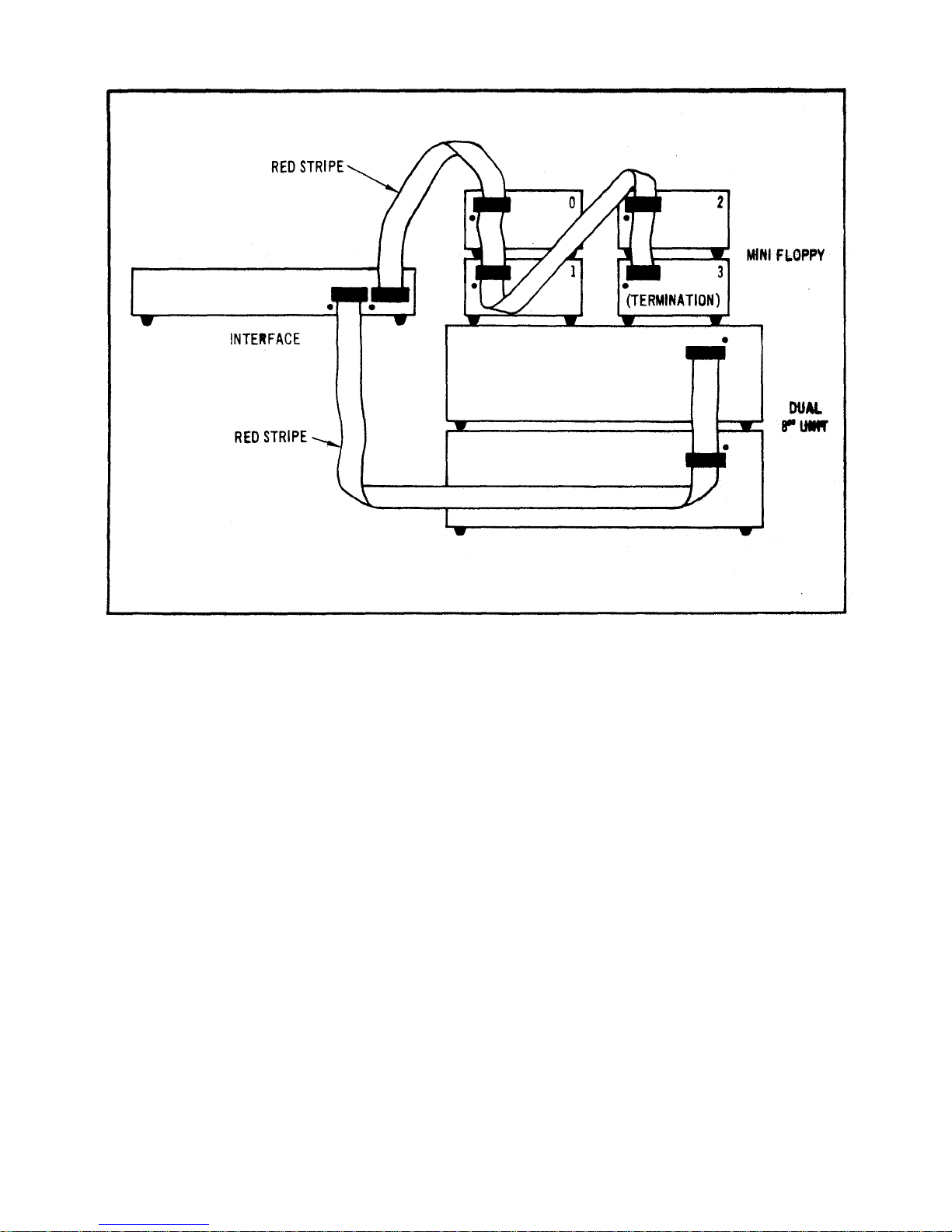
One of the outstanding features of the Model LX80 Expansion Interface is its disk memory expansion
capabilities The interface can support up to four (4) of any of the following disk drives, in any combination,
providing a maximum of 40 million bytes of storage on your TRS-80 computer:
a. 5.25-inch Mini Floppies, single or double density, single or double sided.
b. 8-inch standard floppies, single/double density, single/double sided.
c. LOBO Model 1850T Dual Fixed/Floppy Disk Drives, 5 or 10 Megabyte fixed, up to 1.6 megabytes
floppy (unformatted).

1-2
Connections between the disk drives and the expansion interface are conveniently located on the rear and
side panels. (See Figure 1 -1.) There is a separate bidirectional parallel port exclusively for connecting hard
disk drives.
Other features include: a parallel port that functions like the Centronics printer port on the Radio Shack
interface; a screen printer port; two programmable bidirectional serial ports; and a crystal controlled "Real
Time" clock.
Figure 1-1. LX80 Expansion Interface Peripheral Connections.

2-1
SECTION II
UNPACKING THE INTERFACE
2.1 VISUAL INSPECTION
Before you open the shipping container, visually inspect it for evidence of shipping damage or mishandling, If
such damage is present, a report should be filed with the carrier as soon as possible. Do not remove or
operate the expansion interface if any possibility of damage is evident.
2.2 UNPACKING THE EXPANSION INTERFACE
Carefully unpack the expansion interface and proceed as follows:
a. Check the tag or label on the interface to verify you have received the options you ordered: 16K or
32K of RAM; Dual Serial Communications ports; keyboard power cable; 230 VAC/50Hz power supply
(includes cable).
b. Check that you have a 6-inch, 40-conductor keyboard flat cable.
c. Check that you have a diskette containing the Disk Operating System (DOS) software.
CAUTION
Be very careful when handling the diskette. READ SECTION V DISKETTE CARE before
handling any diskettes.

2-2
2.3 UNPACKING DISK DRIVES
Any disk drives you may have ordered from LOBO DRIVES will be packaged separately. Carefully inspect
and unpack the drives as described in paragraphs 2.1 and 2.2. Check that you have the correct long flat data
cable for your type of drive. Contact your local dealer or LOBO DRIVES if any item(s) is missing.
a. Mini Floppies - require long 34-conductor, five connector cable.
b. Dual 8-inch Floppies - requires a long 50-conductor, two connector cable (three connectors if you
have two dual-drive units.)
c. Model 1850T - same as Dual 8-inch Floppies, plus disk controller unit, power supply and special
cable assemblies.

3-1
SECTION III
SETTING UP THE SYSTEM
Find a space large enough to hold all the components of your system, plus adequate work space. Be sure
you will have enough AC power outlets to run all the components of your system. LOBO DRIVES
recommends the use of a fused, switched power distribution box. To set up your system, proceed as follows:
1. For safety, be sure the entire system is OFF and everything is unplugged from the AC power line.
2. Referring to Figure 3-1, plug one end of the 6-inch keyboard flat cable onto the connector visible
through the slot in the bottom of the interface.
NOTE
The colored wire at the edge of the flat cable should be on the right side when looking at the
front of the interface.
Figure 3-1. Keyboard Flat Cable Installation.

3-2
3. Remove the protective plastic connector cover from the back of the keyboard. Plug the free end of the
interface cable onto the exposed connector
Do not attempt to connect the interface to a keyboard with a DIN cable modification Do not use a
"Buffered" or "Shielded" keyboard cable,
4. Place the video monitor on top of the interface. Plug its DIN cable into the keyboard VIDEO socket.
NOTE
If your interface has no keyboard power cable, skip step 5 and proceed to step 6,
5. Identify the five-conductor DIN cable coming from the rear of the interface Feed the cable under the
interface and plug it into the keyboard's POWER socket.
NOTE
You no longer need the keyboard's old power module, The interface will now supply the correct
keyboard power for 230 VAC installations and the keyboard will run cooler than before. Proceed to
step 8,
6. Plug the keyboard's original power supply module into the POWER socket on the back of the
keyboard.
7 Place power module off to the side. It car cause the picture to squirm if placed too close to the back of
the video monitor.
8. If you have purchased floppy drives place them to one side of the interface and plug them into the flat
cable as shown in Figure 3-2.

3-3
Figure 3-2. Mini and 8" Floppy Disk Connections
NOTE
Check the drive part numbers. Only one drive can contain termination resistors, and that drive
must be the furthest from the interface, Any unused connectors must be at the END of the
cable.
9. If you are installing standard 8-inch floppies, refer to Figure 3-2 and connect the drives using the
supplied flat cable. If you are using one dual-drive unit, then connection is simple. This unit should be
labeled DS1/DS2/TERMINATORS. If you are using two dual-drive units, then you must be sure to
have a double connector cable and two specially configured dual-drive units. The first unit on the
cable must be DS1/DS2/NO-TERMINATORS while the second must be DS3/DS4/TERMINATORS.

3-4
10. If installing a hard disk drive, refer to its own information sheet and connect to the interface.
11. You must set the "drive configuration" switches on the rear panel of the interface. These switches
tell the interface what to do when you power-up or reset the system. Normally, you want the interface to
load the operating system software from your fastest disk drive (this will be DRIVE 0). Refer to Figure
3-3 for the location of the DRIVE 0 select switches. If you have an 8" floppy drive or a hard disk that you
want to be DRIVE 0 then you must have an 8" diskette or a hard disk that contains the disk operating
system software. If your only copy of the operating system is on a mini diskette, they you must select
DRIVE 0 as a mini floppy and proceed as if it were the only drive available to you. Later, you may use
the disk operating system commands to copy the mini disk data onto an 8" floppy or hard disk.
Figure 3-3. DRIVE 0 Configuration Switches.

3-5
NOTE
Selection of DRIVE 1, DRIVE 2, DRIVE 3, . . . depends upon the operating system software.
Refer to the appropriate section in the disk operating system manual.
12. Place the interface's NML-ALT switch in the NML position.
13. Turn all of the units OFF. Plug everything into the AC line (or into the power distributor box), Turn
everything ON following this sequence:
a. Turn ON video monitor.
b. Turn ON drives, (Wait 20 seconds if you have a hard disk drive.)
c. Turn ON interface.
d. Turn ON keyboard.
e. If DRIVE 0 is a floppy drive, refer to DISKETTE CARE and insert the system diskette.
f. Press RESET button on keyboard to "boot in" and run the disk operating system software.
14. At this point, your computer system should be operational. A message on the video display should
indicate that the system is working and awaiting further keyboard commands. Turn to the disk operating
system manual and learn how to use your new system.
15. To turn OFF the system, follow this sequence:
a. Close any files you may have opened. Wait for all disk activity to stop.
b. Remove all diskettes from all floppy drives.
c. Turn OFF everything, sequence doesn't really matter.

4-1
SECTION IV
TROUBLESHOOTING HINTS
Due to the complex nature of the circuitry utilized in the Model LX80 Expansion Interface, user
troubleshooting must logically be limited to a few simple checks. Should an Expansion Interface malfunction
persist after the hints provided in this section are followed, the user should refer the problem to the nearest
LOBO DRIVES dealer or contact LOBO DRIVES directly.
Here are a few hints to help you get your system running:
a. Double-check all connections. Be sure everything is plugged in and turned ON.
b. Check each unit's fuse. Replace defective fuses.
c. Turn up video monitor brightness to verify its operation.
d. Recheck cable orientations against the Figures 3-1 and 3-2.
NOTE
One reversed cable can disable several components. A reversed cable can cause a floppy
drive to erase diskettes.
e. Be sure the NML-ALT switch is in the NML (normal) position.
f. Check the drive serial number. Be sure you have selected the correct DRIVE 0 with the drive
configuration switches (see Figure 3-3).

4-2
g. Check that DRIVE 0 has an operating system diskette in it.
h. Try turning the keyboard OFF for a few seconds, then back to ON.
i. Try setting DRIVE 0 to be "NO DRIVE" (both switches off, see Figure 3-3). Now, press the keyboard
reset button, There will be a 1/2 second pause and then MEMORY SIZE? will appear on the screen (you
are in BASIC LEVEL II). If this message does not appear, or if there is no momentary pause, there is a
problem with the interface or the interface/ keyboard cable.
WARNING
The solid state devices contained in the Expansion Interface are sensitive to static electricity
charges too small for you to feel. Technicians work on them under special anti-static conditions
with grounding straps and other equipment not normally available to user/owners. Unless you
are a trained computer technician, refer all service to your local LOBO DRIVES dealer.

5-1
SECTION V
DISKETTE CARE
Diskettes are precision recording media. Handle them very carefully to get maximum life from each one. In
general, follow the special handling precautions used with both tape cassettes and high fidelity records and
the instructions below:
a. Keep the diskette in its storage envelope whenever it is not in one of the drives.
b. Keep diskettes away from magnetic fields (transformers, AC motors, magnets, etc.). Strong
magnetic fields will destroy data on the diskettes.
c. Handle the diskette by the jacket only. Don't touch any of the exposed surfaces. Don't try to wipe or
clean the diskette surface; you may scratch it and destroy data.
d. Keep the diskette away from heat and direct sunlight.
e. Avoid contamination of the diskette with cigarette ashes, dust, or other particles.
f. Use only felt-tip pens to write on diskette labels.
g. Insert the diskette into a drive carefully. Never force the door closed. Gently remove and reinsert
the diskette.

5-2
h. Remove the diskette from the drive before turning the power ON or OFF.
i. Special "write protect" stickers may be placed over the write protect notch in the edge of the diskette
to protect your data, When a sticker covers the notch of a mini diskette, it becomes impossible for the
computer to add or change information stored on the diskette. The reverse is true for an 8-inch
diskette . . . remove the sticker to write protect the data.

6-1
SECTION VI
TECHNICAL DATA
6.1 MEMORY MAP
ADDRESS USE
0000H-2FFFH alternate ROMs if selected by the switch
3000H- 33FFH disk boot and I/O ROM
37E0H-37E3H read for interrupt code (clears RTC interrupt)
37E8H-37EBH read for line printer and hard disk status, write
for line print output
8000H-BFFFH first 16K RAM add-on
C000H-FFFFH second 16K RAM add-on
6.2 INPUT/OUTPUT PORT MAP
PORT INPUT OUTPUT
E0 hard disk data hard disk data
E1 floppy FIFO data floppy FIFO data
E2 FIFO counter FIFO mode (0-read, 1-write)
E3 dip switch floppy select and modes
E4 1791 status register 1791 command register
E5 1791 track register 1791 track register
E6 1791 sector register 1791 sector register
E7 1791 data register 1791 data register
E8SIO data A SIO data A
E9 SIO data B SIO data B
EA SIO status A SIO command A
EB SIO status B SIO command B

6-2
PORT INPUT OUTPUT
EC -- BAUD rate A
ED -- BAUD rate B
EE -- --
EF -- --
FC -- --
FD -- --
FE -- --
FF -- reset boot logic
6.3 INTERFACE SPECIFICATIONS
a. Outside dimensions:
Height 2.8" (7 cm)
Width 19.0" (48 cm)
Depth 11.8" (30 cm)
b. Power Requirements:
117VAC 60HZ or 235VAC 50HZ (internally jumpered)
Three wire (grounded) power cord
40 watts
c. Maximum number of disk drives:
Depends upon software, hardware can run four single or double-sided mini floppies, plus four single or
double-sided 8" floppies, plus any number of hard disk drives (limited only by the type of hard disk drives
used).

6-3
d. Disk storage (maximum formatted, depends upon software):
SA-400 (single sided mini floppy drive)
single density 89K bytes
double density 161K bytes
SA-450 (double-sided mini floppy drive)
single density 179K bytes
double density 322K bytes
SA-800 (single sided 8" floppy drive)
single density 335K bytes
double density 611K bytes
SA-850 (double sided 8" floppy drive)
single density 670K bytes
double density 1,222K bytes
e. Real time clock (RTC)
Interrupts CPU every 25 milliseconds, crystal accuracy
f. Two RS-232 serial channels (both identical):
Controller Zilog's Z80-SIO/2
Serial formats: ASYNC, SYNC (with CRC), HDLC & SDLC
Baud rates: programmable, 12.5 to 316.8K
Cable configuration selected by jumper plugs
g. Alternate ROMs:
Replace keyboard ROMs (0000H-2FFFH) by toggling switch
Three 24-pin sockets are configured by a jumper plug to accept one type of ROM: 2708s, 2716s, or 2732s
Alternate-ROM code runs about 30% slower than in RAM
h. Expansion port:
A duplicate of the keyboard port, except for no +5V power on pin 37,
i. Parallel printer port: Talks to a Centronics-like printer.

6-4
6.4 INSTALLING YOUR OWN 16K RAM
a. It is easy for you to install your own RAM chips that you can purchase as an upgrade kit. Simply UNPLUG
THE INTERFACE AC CORD, remove the two cover screws, and carefully lift the cover.
b. The first eight RAM chips will go into the bottom row of sockets at the right side of the circuit board. The
second set of eight will go into the upper row. One at a time, push the new chips into their sockets. Be sure
that the orientation notch points toward the top of the circuit board (the way all the other chips go). Be very
careful not to bend any of the pins. After inserting all of the chips, double check your work, then reassemble
the cabinet.
c. Now, load in BASIC and do a PRINT MEM. Do you have 16,384 more bytes than before?
6.5 CONFIGURING THE ALTERNATE ROM JUMPER PLUG
a. To use the alternate ROM sockets, first open the cover: UNPLUG THE INTERFACE AC CORD, remove
the two screws, and carefully lift the cover. Remove the 16-pin jumper plug from the circuit board (just above
the ROM sockets, mounted sideways). Refer to the guides below and solder jumpers across the removed
plug. Don't melt the plastic. Reinsert the plug (pin 1 is oriented toward the upper-right corner), insert your
ROMs into the three sockets (the leftmost socket is at address 0000H) and reassemble the cabinet.
NOTE
AMP brand sockets are Mil-spec devices that sometimes require puller tools to remove the ICs.
b. Jumpering for 2308s, 2708s (+5v, -5v, +12v):
Connect pins 1-4, 2-3, 9-19, 12-13-14-15
Table of contents
Popular Computer Accessories manuals by other brands

ZALMAN
ZALMAN Z11 Plus user manual

Apevia
Apevia X-Cruiser user manual

TerraTec
TerraTec ModdingSystems MYSTIFY H2O 2010 Product information

Fujitsu
Fujitsu Silicone Sleeve user guide

Microchip Technology
Microchip Technology MPLAB ICD 4 user guide

Pro-Ject Audio Systems
Pro-Ject Audio Systems usb box Instructions for use