Latch speed.
Velocidad picaporte.
Fast.
Rápido.
Slow.
Lento.
Closing speed.
Velocidad de cierre.
PARA UTILIZAR LA PLANTILLA DOBLE ESTA ORILLA / TO USE THE TEMPLATE FOLD THIS SIDE.
L5243AL
L5241AL
L5242AL
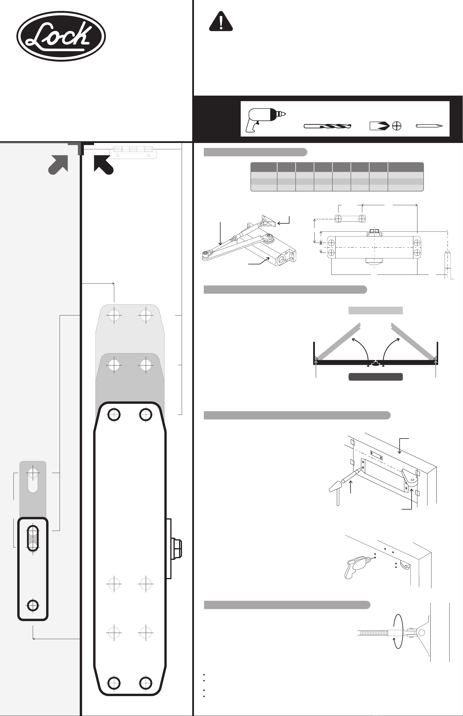
Coloque en la esquina del
marco de la puerta.
Place in the corner of the
door frame.
105 mm
95 mm 130 mm
20 mm
135 mm 165 mm
PLANTILLA PARA
INSTALACIÓN DEL CUERPO
BODY INSTALLATION TEMPLATE
PLANTILLA PARA
INSTALACIÓN DE LA ZAPATA
LINK SHOE INSTALLATION TEMPLATE
29 mm
DERECHA / RIGHT HAND
CIERRA PUERTA
DOOR CLOSER
Coloque en la esquina
del marco (lado de la
bisagra).
Place on the corner of top
Jamb forward the hinge.
Urrea Herramientas Profesionales S.A. de C.V. km 11,5 Carretera A El Castillo, El Salto, Jalisco, México. C.P. 45680, Tel. (33) 3208 7900,
RFC UHP900402Q29, garantiza este producto por el termino de 100 años en sus piezas, componentes y mano de obra contra cualquier defecto de fabricación a partir de la fecha de
entrega.
Condiciones: Para hacer efectiva la garantía deberá presentar el producto junto con la póliza de garantía debidamente firmada y sellada por el establecimiento donde la adquirió, en
cualquiera de los centros de servicio autorizados. Los gastos de transportación que se deriven del cumplimiento de la garantía serán cubiertos por Urrea Herramientas Profesionales
S.A. de C.V. Esta garantía no será valida en los siguientes casos:
· Cuando el producto haya sido utilizado en condiciones distintas a las normales o al desgaste natural de sus partes.
· Cuando el producto no haya sido operado de acuerdo al instructivo de uso que lo acompaña.
· Cuando el producto haya sido alterado o reparado por personas no autorizadas.
Urrea Herramientas Profesionales S.A. de C.V. km 11,5 Carretera A El Castillo, El Salto, Jalisco, México. C. P. 45680, Tel. (33) 3208 7900, RFC UHP900402Q29,
warranties this product for a life time in its parts, components and manual labor against any manufacture defect from the purchasing date.
Terms: In order to make warranty effective you must present the product along with the warranty properly filled and signed to an authorized distributor or
service center. Urrea Herramientas Profesionales S.A. de C.V. will cover the transportation cost related to the warranty.
This warranty is not applicable in the following cases:
· When the product has not been used according to normal conditions or natural wear of its parts.
· When the product has not been used according with this user’s manual instructions.
· When the product has been fixed or modified by unauthorized or unqualified person.
L5241AL
L5242AL
L5243AL
40 mm
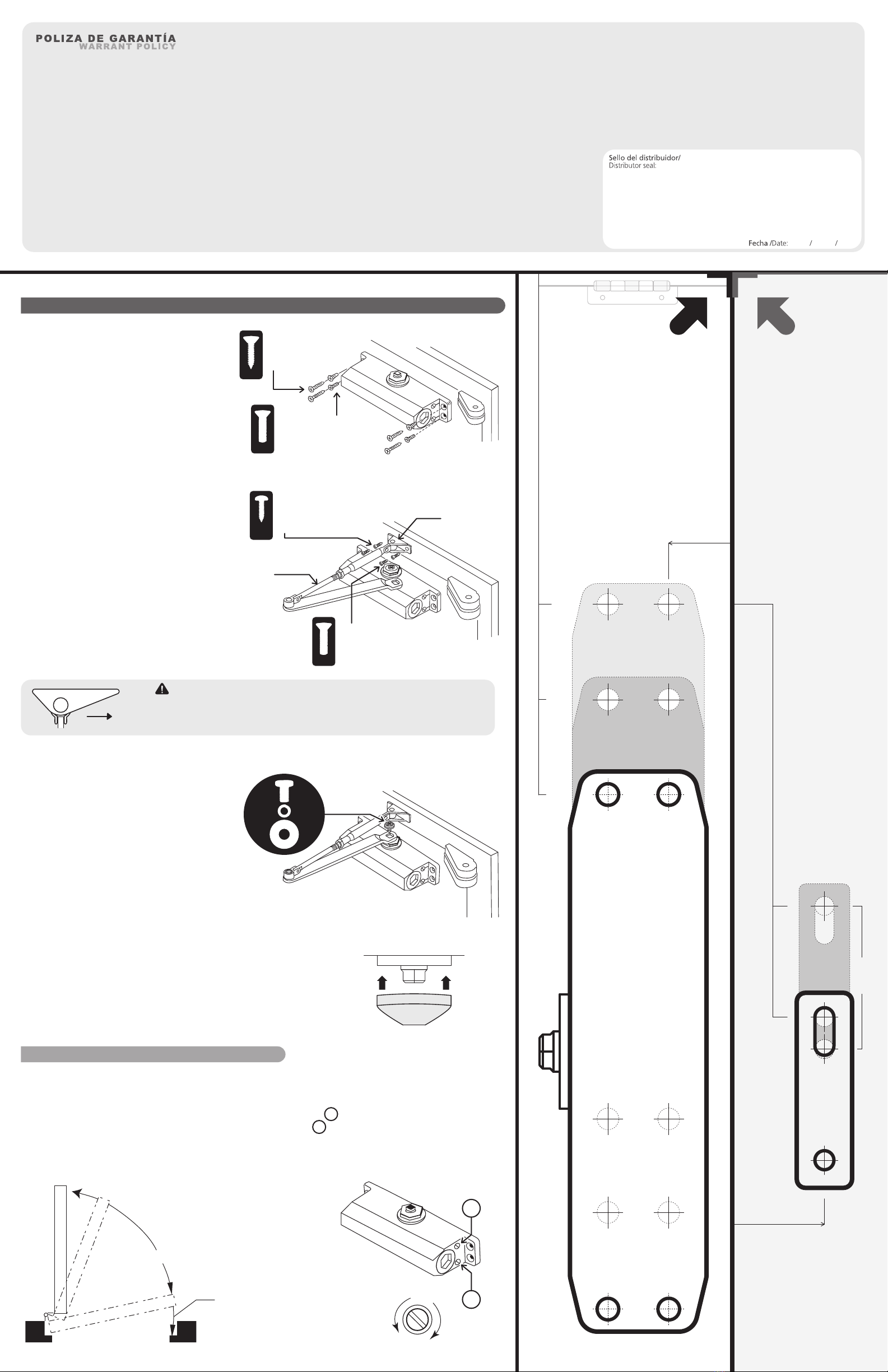
BODY INSTALLATION
INSTALACIÓN DEL CUERPO
Mount body in the door and tighten securely
with the 4 screws provided.
Monte el cuerpo en la puerta y apriete
firmemente con los 4 tornillos
suministrados adecuados al material.
1. Para puertas
de madera.
For wood doors.
Para puertas
de metal.
For metal doors.
INSTRUCCIONES DE INSTALACIÓN /INSTALLATION INSTRUCTIONS:
SHOE INSTALLATION
INSTALACIÓN DE LA ZAPATA
a) Unscrew the link until it reaches the door frame.
b) Install the shoe with the appropriate screws
supplied.
NOTE: Make sure the guide is perpendicular to the
frame when installing.
a) Destornille la guía hasta alcanzar el
marco de la puerta.
b) Instale la zapata con los tornillos
suministrados adecuados al material.
NOTA: Asegúrese que la guía esté
perpendicular al marco cuando instale.
2.
COMPLETE INSTALLATION
COMPLETE LA INSTALACIÓN
Put pinion cap onto the and complete the installation.
Ponga la tapa del piñon para completar la instalación.
4.
INSTALL ARM WITH BODY
INSTALACIÓN DEL BRAZO MÓVIL
CON EL CUERPO
Attach the square inlet with the end of the
pinion to the body, place the screw, split lock
washer and washer. Tighten firmly.
Ensamble la entrada cuadrada de la
guía con el extremo del piñon en el
cuerpo. Coloque el tornillo, arandela de
presión y rondana. Apriete firmemente.
3.
Para marcos de
madera.
For wood frames.
Para marcos
de metal.
For metal frames.
Guía.
Link.
Zapata.
Shoe.
x4
x4
x2
x2
x1
1
2
AJUSTES FINALES /FINAL SETTINGS
SPEED ADJUSTMENT OF THE DOOR AND LATCH
AJUSTE LA VELOCIDAD DE LA PUERTA Y PICAPORTE
Adjust closing speed by turning 1st screw.
Adjust latch speed by truning 2nd screw. Turn screw clockwise to reduce speed.
Ajuste la velocidad de cierre de la puerta girando el tornillo 1 .
Ajuste la velocidad de picaporte (final) girando el tornillo 2 . Girar el tornillo en sentido de
las manecillas del reloj reducirá la velocidad.
IMPORTANTE: El extremo más largo de la zapata tiene que estar
direccionado a la bisagra (sin importar de que lado se instale).
IMPORTANT: The steepest part of the shoe must be directed to the hinge
(regardless of which side is installed).
Hinge
Bisagra
PAG. 2-2