F.C.C. PART 15 INTENTIONAL RADIATOR MANUAL STATEMENT
RADIO FREQUENCY INTERFERENCE STATEMENT
Note, this equipment has been tested and found to comply with the
limits for an intentional radiator, persuant to Part 15, subpart C of the
F.C.C. Rules. This equipment generates uses and can radiate radio
frequency energy. If not installed and used in accordance with the
instructions, it may cause interference to radio communications.
The limits are designed to provide reasonable protection against such
interference in a residential situation. However there is no guarantee
that interference will not occure in a particular installation. If this
equipment does cause interference to radio or television reception,
which can be determined by turning the equipment on and off, the user
is encouraged to try to correct the interference by one or more of the
following measures:
qReorient or relocate the receiving antenna of the affected radio or
television
qIncrease the separation between the equipment and the affected
receiver.
qConnect the equipment and the affected receiver to power outlets
on separate circuits.
qConsult the dealer or experienced radio/TV technition for help.
MODIFICATIONS
Changes or modifications not expressly approved by Skidmore 4wd
Ltd. could void the users authority to operate the equipment
Skidmore 4WD Limited Warranty for LODAR Valid Worldwide
Limited Warranty.
Skidmore 4wd Ltd (“Seller”) warrants to the original buyer (“You”) all parts and components to be free of faults in materials workmanship for a period of two (2) years
from provable date of purchase. Any Lodar product that is faulty will be repaired or replaced without charge to you, upon compliance with these procedures. The
Warranties set forth herein are exclusive and in lieu of all other Warranties, whether oral or written, express or implied.
Limited Warranty Performance Procedure
Upon discovery of a faulty Lodar product, you shall notify the Seller in writing, at his factory or at any authorised distributor, details of the said fault and mail, or
otherwise ship the faulty Lodar product, postage or other carriage prepaid. Repairs or replacements by the Seller under this Limited Warranty will normally be
accomplished within fifteen (15) working days after the receipt of the faulty Lodar product. The Seller, or its authorised distributor, may make reasonable charges for
repairs that are not covered by this Limited Warranty
Warranty and Remedy Limitations and Exclusions
The following exclusions or limitations of Warranties and limitations of remedies shall be expressly applicable:
Express Warranties.Seller warrants that the Lodar is as described in the “Lodar Owners Manual” provided herewith: no other express Warranty is made in respect to
the Lodar. If any model or sample was shown to you, such model or sample was used for illustrative purposes only, and shall not be construed as a Warranty that the
Lodar will conform to the sample or model.
Implied Warranties. The implied Warranty of merchantability and all other implied Warranties shall only extend from the provable date of purchase for two(2) years.
Some States within the USA do not allow limitations on how long an implied Warranty lasts, so the above limitation may not apply to you.
Incidental and Consequential Damage. Subject to the Sellers Limited Warranty obligations set forth herein, the Seller shall not be responsible for incidental damages
of any kind, or for consequential damages to property, loss of profits and loss of use which may be caused by any fault in, or malfunction, or failure of the enclosed
Lodar. Some States within the USA do not allow the exclusion or limitation of incidental or consequential damages, so the above limitation may not apply to you.
Condition of Warranty. The Seller shall not be required to comply with its Warranty duties provided herein if the fault, malfunction or failure of the Lodar was caused
by damage (not resulting from faulty or malfunctioning components) or unreasonable use by you. Unreasonable use shall include, but not be limited to, the failure to
provide reasonable and necessary maintenance or installation or use of the Lodar without compliance with the instructions contained in the Lodar Owners manual.
Sellers liability under this Warranty or for any loss or damage to the Lodar product shall not exceed the cost of correcting the defects in or replacing the Lodar product,
and upon expiration of the Warranty period, all such liability shall terminate. The agents, distributors and employees of the Seller are not authorised to make
modifications to this Warranty, or additional Warranties binding on the Seller. Accordingly, additional statements, whether oral or written, do not constitute Warranties
and should not be relied upon.
Legal Remedies of the Buyer
This limited Warranty gives you specific legal rights, and you may also have other legal rights, which may vary from State to State within the USA and from country to
country. You also have implied Warranty rights. In the event of a problem with Limited Warranty service or performance, you may be able to go to a small claims court,
a state court or a federal district court in the USA or to appropriate jurisdictions outside the USA.
Enquiries
Any enquiries regarding compliance with Warranties provided herein may be addressed in writing to:
Skidmore 4WD Limited, 60 Sandwell Street, Walsall WS1 3EB, England.
We, Skidmore 4wd Ltd., 60 Sandwell St., Walsall. WS1 3EB England.
Declare under our sole responsibility that the product:
Product Details Name - Lodar
Series - 92
Type - 92 x 20
To which this declaration relates is in conformity with the essential
requirements and other relevant requirements, and is compliant with the
standards and/or other documents, of the following directives :
EN 301 489-3
R&TTE (1999/5/EC)
Safety Low Voltage Directive 300.683
EMC 2004/104/EEC ETSI 300-220 v1.1.1
Automotive EMC Approval Granted - e11*72/245*95/54*3087*00
FCC Approval Granted
Spectrum 433.92 MHz F1D (EUROPE )
418.0 MHz F1D (USA)
Please note that this certificate only covers Lodar and not the installation
Martin Skidmore Position Date
CEO September 2009
TRANSMITTER REGISTRATION - IF YOUR LODAR DOES NOT WORK TRY THIS FIRST
During transit security scanning can sometimes cause a Receiver to loose the Transmitter registration in its
memory.
To register a Transmitter to Receiver.
Step 1. Switch OFF or DISCONNECT the power to the Receiver.
Step 2. Switch ON or Reconnect the power to the Receiver.
This opens a 20 second registration window in the Receiver processor.
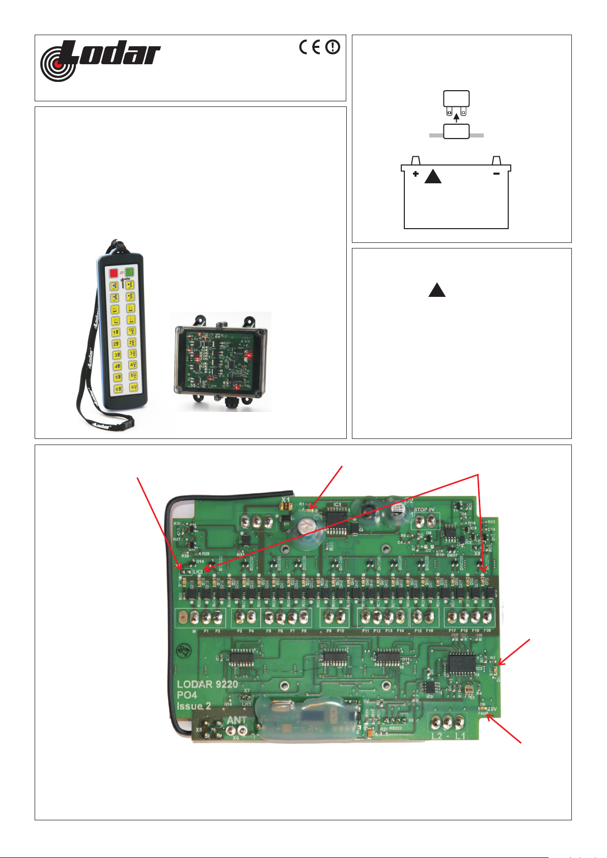
If you are looking at the Receiver PCB the Fault LED Flashes.
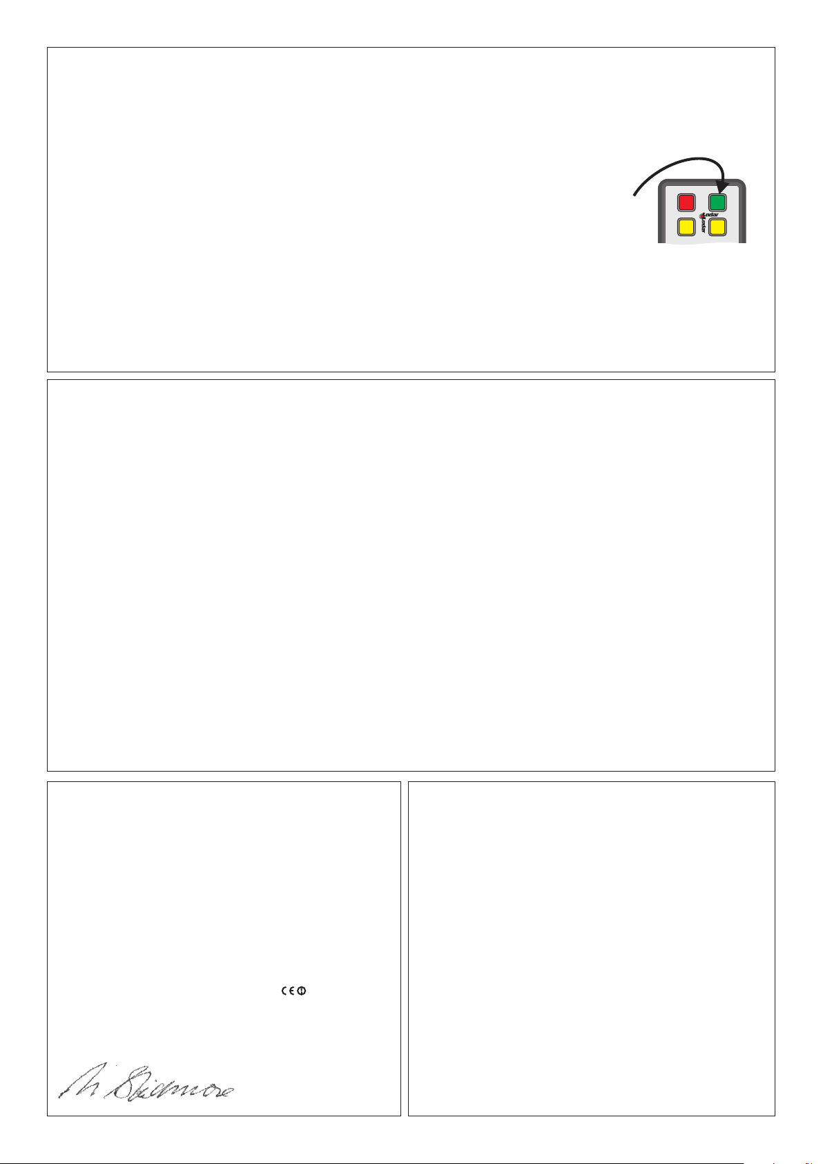
Step 3. Immediately PRESS and HOLD the Transmitter Reset Button (The Green Button)
for a minimum of 10 seconds during this 20 second window.
When the Transmitter is Registered the Fault LED goes out, and the Set LED comes on.
Your Transmitter is now operating the Receiver.
1 2
PRESS
&
HOLD