Loepfe YARNMASTER ZENIT+ Installation manual

YARNMASTER ®ZENIT
50338003 en
V 5.9.x.x / 03.2019
First Startup
Step by Step

Loepfe Brothers Ltd.
Kastellstrasse 10
8623 Wetzikon/Switzerland
Phone +41 43 488 11 11
Fax +41 43 488 11 00
E-Mail service@loepfe.com
Internet www.loepfe.com
This Instruction Manual is protected by copyright.
Complete or partial reproduction and dissemination of this
Instruction Manual to third parties – even in form of extracts
– as well as the use and /or disclosure of the contents are not
allowed without the written approval of Loepfe Brothers Ltd.,
except for internal purposes.
YarnMaster®is a registered trademark of Loepfe Brothers Ltd.
in Switzerland and / or in other countries.
© 2019 Loepfe Brothers Ltd., Switzerland

3
First Startup Zenit+
Variant 1
External power supply
24 V DC
Variant 3
External power supply
24 V DC
Variant 2
External power supply
90–264 V AC
Central unit (LZE-V)
Power
supply
unit
24 V DC
Spindle
adapter
(SA)
Loepfe 2-wire-bus (L2B)
LAN connection (crossover cable)
Sensing head cable
Sensing head (TK)
1 Installation
Spindle
computer
or
All cable connections are pluggable.
Central unit
(LZE-V Faceless)

First Startup Zenit+
4
2 Connections LZE-V
Front USB interface (USB port) for import /
export of settings and data as well as
screenshots.
A removable cap protects the USB
interface from dust and humidity.
Rear
24 V DC -
+
Marking Type Description
Power Sub D PSC Power supply 24 V DC
Contact 1 (+ ) 24 V DC
Contact 2 not connected
Contact 3 ( –) 0 V DC
ATTENTION
Only 24 V DC may be supplied to this
connection!
Threaded connection Protective ground
DANGER
This separate grounding point must be
connected with the protective ground!
LOEPFE 1 Sub-D,
9-pole connector
Connection of Loepfe 2-wire bus (L2B)
PWR LED green / red Power supply OK
HDD LED red Compact-flash drive active

5
First Startup Zenit+
Marking Type Description
Microswitch
(Power ON/OFF)
LED green Tap
< 1 Sec.
Switch to standby mode con-
trolled by operating system
(LED becomes orange)
LED green Press
> 1 Sec.
Only in emergencies!
Forced, uncontrolled switch
to standby mode
(LED becomes orange)
Unsaved data are lost!
LED orange Tap
< 1 Sec.
Start
(LED becomes green)
LAN 1 RJ45 Dedicated connection for LZE-V Faceless
IP: 192.168.1.200 (Default)
Attention: Mistakenly changing the LAN 1 IP address
might cause the LZE-V to lose the required communica-
tion link to the Savio PC!
LAN 2 RJ45 Connection for network
IP: DHCP (Default)
USB 2.0 USB port
Display port (HDMI) DP, maximum resolution 1600 x 1200
COM 1 Sub-D,
9-pole connector
RS 485
COM 2 Sub-D,
9-pole connector
RS 232

First Startup Zenit+
6
3 User Interface / Navigation
1 Main navigation
2 Menu contents (list, overview, details)
3 Navigation path
4 Selection bar for group/ spindle or article
5 Message window
6 Messages requiring intervention
7 Data selection filter (Dashboard, Monitoring and Quality menus)
8 Login / access level
9 Language selection
10 Online help
11 Action buttons / function buttons
12 Connection status (Ethernet / MillMaster TOP / Remote / Data Exist)
13 Active user level / logged on user
14 Date / time
15 Software version
16 Switch-over Loepfe / Savio GUI (only LZE-V Faceless)
516 6
3
7 8 9 10
1
4
2
11
12
13
14
15

7
First Startup Zenit+
Language selection
Login / access level
Online help
List of messages requiring
intervention
Create screenshot /
save on USB stick
Create reports /
save on USB stick
Data export / import
Back
Next
Edit settings
Confirm selection / input
Cancel selection / input
Undo input
Copy article
Start lot / group
Stop lot / group
Adjust
(groups / spindles in production)
Reset monitoring data /
quality data
Change password
Logout / user logout
Add user
Delete user
Acknowledge last message
Acknowledge all messages
Firmware Update
Input information
Function Buttons

First Startup Zenit+
8
4 Language Selection
1. Tap Language button.
5 Login
1. Tap Login button.
3. Tap password input field.
5. Confirm entry with .
2. Select user “Foreman”.
(Foreman login is required for all settings during
initial start-up.)
4. Enter Foreman password (=12911291).
2. Select desired operator language.
6. Confirm password / Login with .

9
First Startup Zenit+
SERVICE > Setup >Date and Time
1. Activate the Edit mode by tapping .
2. Enter date / day.
3. Enter time (hour, minutes, seconds).
4. Confirm each entry with .
6 Set Date and Time
5. Save date and time with .
6. Confirm pop-up “Save date and time settings” with .

First Startup Zenit+
10
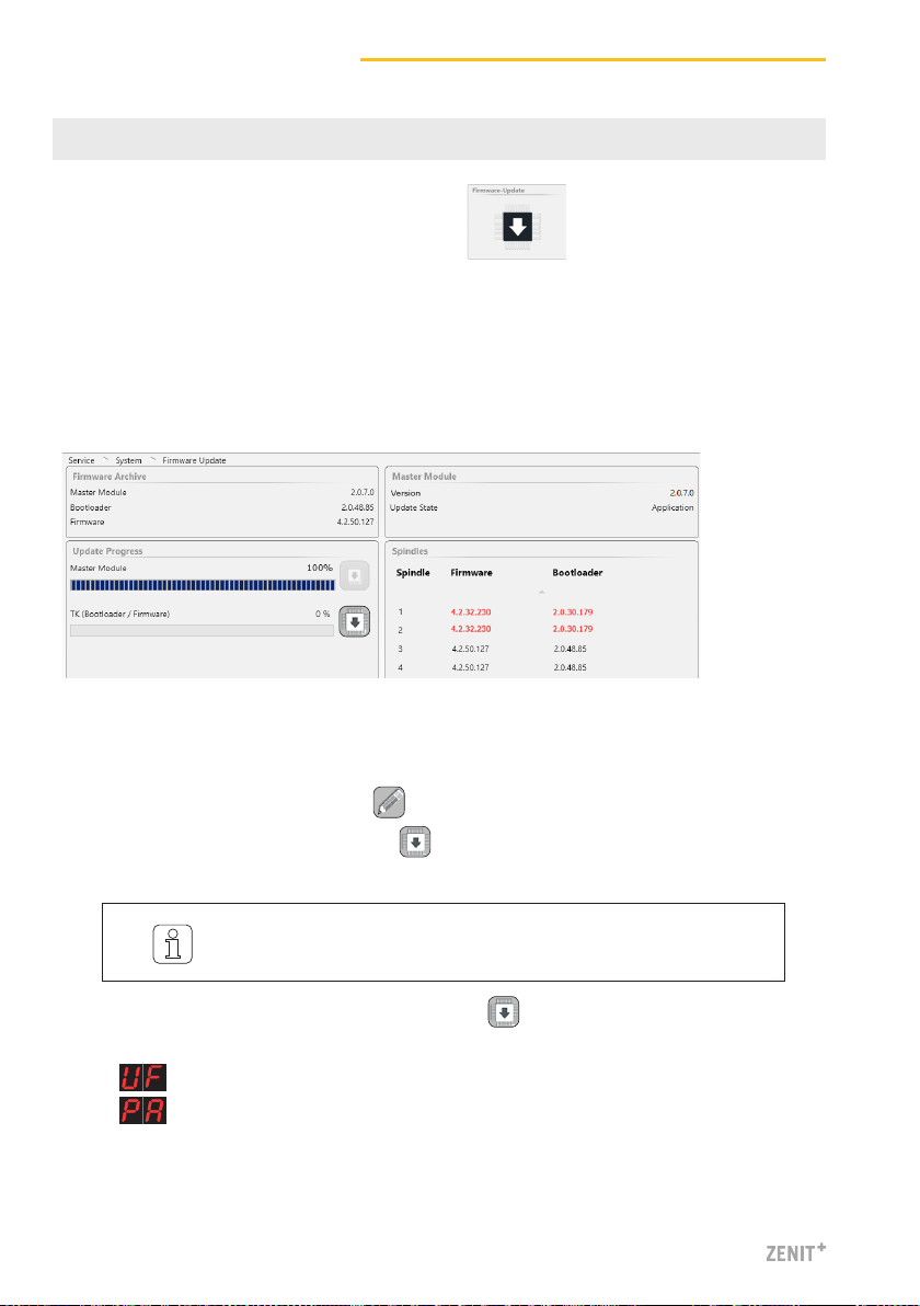
SERVICE >System >Firmware Update
7 Firmware Update
3. Start the TK (Bootloader / Firmware) update with .
»The status of the update is displayed in the progress bar.
»(Update Firmware) is displayed for all sensing heads which do not match.
»is displayed after a successful update.
4. Check firmware and bootloader version of the spindles.
5. Terminate the firmware update.
Master Module, Bootloader and Firmware Versions
The versions shown in the “Master Module” field and in the “Spindles” field must match the
versions shown in the “Firmware Archive” field.
Perform the Firmware Update
A firmware update must be performed if the versions do not match:
1. Activate the edit mode by tapping .
2. Start the Master Module update with .
»The status of the update is displayed in the progress bar.
»Red version number: versions do not match
»Grey version number: TK is offline
It can take some time (30s) until the update is terminated and the
respective next update button becomes active!

11
First Startup Zenit+
SETTINGS > Machine
8 Check and Complete Base Settings
1. Activate the edit mode by tapping .
2. Check and complete the base settings as follows:
Machine Type Read only
Machine Name Enter name (optional)
MillMaster Link On / Off
Total Spindles Enter total number of
winding units of machine
Yarn Count Unit Select unit (Nm, Ne, Tex, Den)
Sensing Head Type Installed sensing head type
(D, DF, DFP)
Splice Check Length Use default setting
Previous Shift km / kg
>Default Group Settings
6. Use default settings.
7. Return to the overview with .
> Default Data Acquisition
8. Use default settings.
3. Save settings with .
4. Confirm pop-up “Save machine settings!” with .
5. Return to the overview with .
> Base Settings

First Startup Zenit+
12
9 Define a Group
SETTINGS > Group (List)
1. Select group no. 1.
2. Double-clicking group no. 1 in the list opens the
overview of the respective group settings.
3. Activate the edit mode by tapping .
> Settings Group
4. First Spindle / Last Spindle: Enter spindle range (first
and last spindle of the group)
5. Article: Tap entry field and select a predefined article
from article list.
> Settings Optional
6. Use default settings.
>Data Acquisition
7. Use default settings.
8. Save group settings with .

13
First Startup Zenit+
10 Start Group
SETTINGS > Group (List)
1. Select group no. 1.
2. Start group no. 1 with .
3. Confirm pop-up“Start Group” with .
»(Adjust) is displayed for all sensing heads.
Afterwards, an adjustment must also be performed for each non-pilot spindle.
»The Ad display goes out for each non-pilot spindle when adjustment is terminated.
The adjustment is started:
»“Production” is displayed in column “Status” and “Active” in column “Adjust”.
4. Start and monitor the respective number of pilot spindles individually.
»The Ad display goes out for each pilot spindle when adjustment is terminated.
After successful adjustment of all pilot spindles:
»“Completed” is displayed in column “Adjust”
If “Completed [x]” is displayed after adjustment, it was not possible
to complete adjustment with all pilot spindles. In this case it is recom-
mended to repeat adjustment with other pilot spindles! The other
spindles may be started only when adjustment status “Completed” is
displayed!

First Startup Zenit+
14
Sensing Head Display
A 1 F 00
E G 00
H 1
with = class cut without = channel cut
C 00 D 00
with = thin place without = thick place
S 1 R 1
I 1 O 1
with = bright without = dark
Nep Joint nep
Short Joint short
Long Joint long
Thin Joint thin
with = class cut without = channel cut
flashing display indicates ALARM (selected no. of repetitions reached)
Sensing Head Display
Cut Type
Nep - unclassified Long - unclassified
Short - unclassified Thin - unclassified
Off Count SFI / D
Short Off Count VCV
with = minus without = plus
Cluster nep Upper Yarn
Cluster short Bunch
Cluster long
Cluster thin
F (foreign matter) F Cluster
with = bright without = dark
P(synthetics)
Zeroing
flashing display indicates ALARM (selected no. of repetitions reached)
Class Type
Yarn runs – Diameter difference _< + / - 10 %
Yarn runs – Diameter difference > +10 %
Yarn runs – Diameter difference > -10 %
Technical Alarm (alternating)
Cutter supply or coil failure (alternating)
Internal power supply failure TK (alternating)
No NTP signal (alternating)
Knife blocked (alternating)
Zeroing failed (alternating)
Spindle cycle timeout (alternating)
Class Alarm
Off Limit Alarm
IPI Alarm
Adjust
Doffing
Waiting for spindle communication
Waiting for central unit parameters
Spindle locked, group not started
Reset
Update TK Firmware
Cut by spindle
Zeroing failed
Cut by user (Test / Reset button)
D brightness regulator out of limit
F brightness regulator out of limit
Adjust cut
Cut failed
Adjust failed
Configuration changed by LZE
Spindle power failure
Spindle System Info
System Cuts
Technical Alarms
Textile Alarms
50320003 en


Loepfe Brothers Ltd.
8623 Wetzikon / Switzerland
Phone +41 43 488 11 11
Fax +41 43 488 11 00
www.loepfe.com
Subject to technical modifications
Other manuals for YARNMASTER ZENIT+
1
Table of contents
Popular Controllers manuals by other brands

Datakom
Datakom D-300 MK2 user manual

MKS
MKS 937B Series Operation and maintenance manual

Mitsubishi Electric
Mitsubishi Electric MELSEC iQ-R Series user manual

KOHSEL ELEPHANT
KOHSEL ELEPHANT M40 installation guide

Larson Electronics
Larson Electronics EXP-MTSTR-DOL-3P-480V-5HP-5A instruction manual

Multiplex
Multiplex ROXXY PROcontrol Series manual