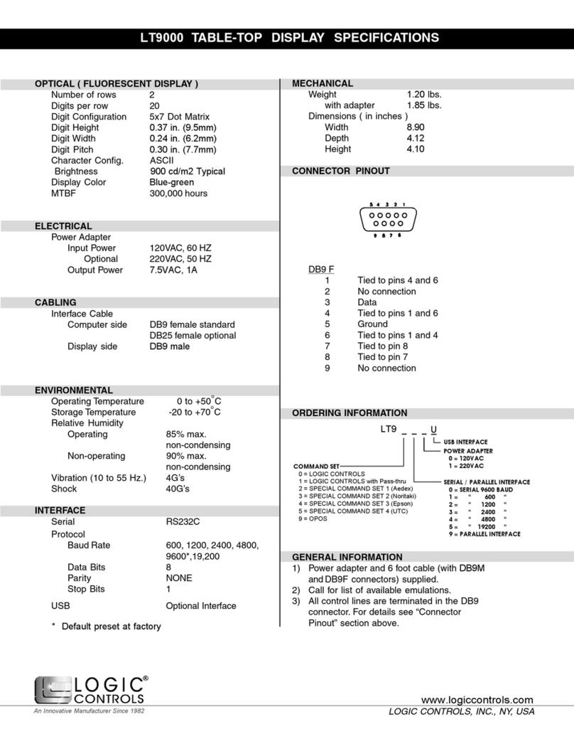
OPTICAL (FLUORESCENT DISPLAY)
Digits per Row 20
Number of Rows 2
Digit Configuration 5 x 7 Dot Matrix
Digit Height 0.44 in. (11.25mm)
Digit Width 0.28 in. (7.2mm)
Character Configuration ASCII
Brightness 204 fl (700 cd/m2) max.
Display Color Green
MTBF 300,000 hours
ELECTRICAL
Input Power (to adapter) 120VAC, 60Hz
220VAC, 60Hz (optional)
Output Power (from adapter) 7.5VAC, 1000mA
Connector 2 conductor female jack
Pole Connector 6-pin DIN (male)
Interface Cable
Pole side connector 6-pin DIN (female)
Computer side connector DB9 (female)
Power connector 2 conductor male jack
ENVIRONMENTAL
Operating Temperature -20 to +70C
Storage Temperature -40 to +85C
Relative Humidity
Operating 85% max. non-condensing
Non-operating 90% max. non-condensing
Vibration (10 to 55 Hz) 4 G's
Shock 40 G's
INTERFACE
Serial RS232C
Protocol:
Baud Rate 600, 1200, 2400, 9600*, 19,2000
Data Bit 8
Parity None
Stop Bits 1, 2*
RTS/CTS Control lines are tied together in the connector.
DSR/DCD/DTR Control lines are tied together in the connector.
Parallel Optional Interface
Pass-Thru Serial, Parallel
* Preset at Factory
GENERAL INFORMATION
Power adapter and 6 foot cable (with DIN 6F and DB9F connectors) are
supplied with product.
POLE DISPLAY EMULATION
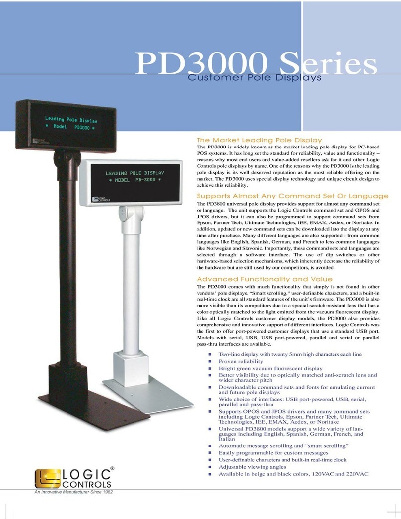
The PD6000 series pole display is extremely versatile. It can
emulate many pole display command sets and support OPOS.
MECHANICAL
Weight 3.1 lbs.
Dimensions (in inches) (width x height x depth)
Fluorescent Display 11.00 x 3.24 x 1.72
Rectangular Base 2.12 x 2.00 x 2.25
Base Plate 4.00 x 0.90 x 8.00
Overall Height 8 to 25 inches
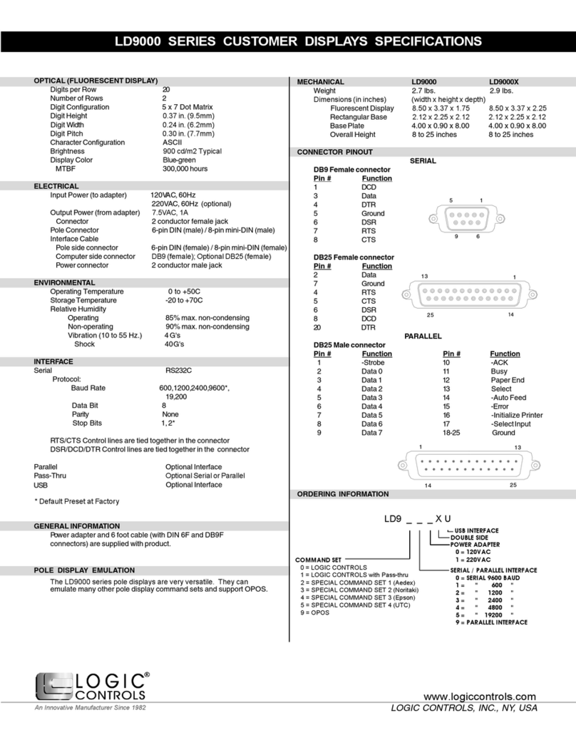
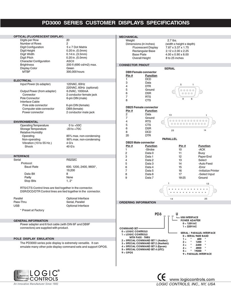
CONNECTOR PINOUT
SERIAL
DB9 Female connector
Pin # Function
1 DCD
3 Data
4 DTR
5 Ground
6 DSR
7 RTS
8 CTS
DB25 Female connector
Pin # Function
2 Data
7 Ground
4 RTS
5 CTS
6 DSR
8 DCD
20 DTR
PARALLEL
DB25 Male connector
Pin # Function Pin # Function
1 -Strobe 10 -ACK
2 Data 0 11 Busy
3 Data 1 12 Paper End
4 Data 2 13 Select
5 Data 3 14 -Auto Feed
6 Data 4 15 -Error
7 Data 5 16 -Initialize Printer
8 Data 6 17 -Select Input
9 Data 7 18-25 Ground
ORDERING INFORMATION
PD6000 SERIES CUSTOMER DISPLAYS SPECIFICATIONS
1
1
1
5
6
9
13
14
25
13
14 25
POWER ADAPTER
0 = 120VAC
1 = 220VAC
SERIAL / PARALLEL INTERFACE
0 = SERIAL 9600 BAUD
1 = " 600 "
2 = " 1200 "
3 = " 2400 "
4 = " 4800 "
5 = " 19200 "
9 = PARALLEL INTERFACE
COMMAND SET
0 = LOGIC CONTROLS
1 = LOGIC CONTROLS
WITH PASS - THRU
LOGIC CONTROLS, INC., NY, USA
An Innovative Manufacturer Since 1982
www.logiccontrols.com
USB INTERFACE
USB Optional Interface
2 = SPECIAL COMMAND SET 1 (Aedex)
3 = SPECIAL COMMAND SET 2 (Noritaki)
4 = SPECIAL COMMAND SET 3 (Epson)
5 = SPECIAL COMMAND SET 4 (UTC)
9 = OPOS
