LogicPower EA33KTLSI User manual

1
Table of Contents
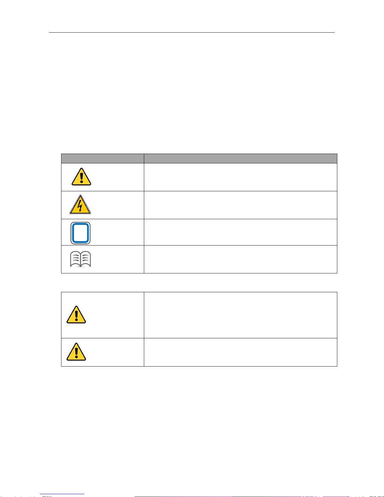
1 Important Safety Instructions............................................................................................................................................2
2 Product Overview.............................................................................................................................................................3
2.1 Product description............................................................................................................................................... 3
2.2 Product features.................................................................................................................................................... 3
2.3 Working principle ..................................................................................................................................................4
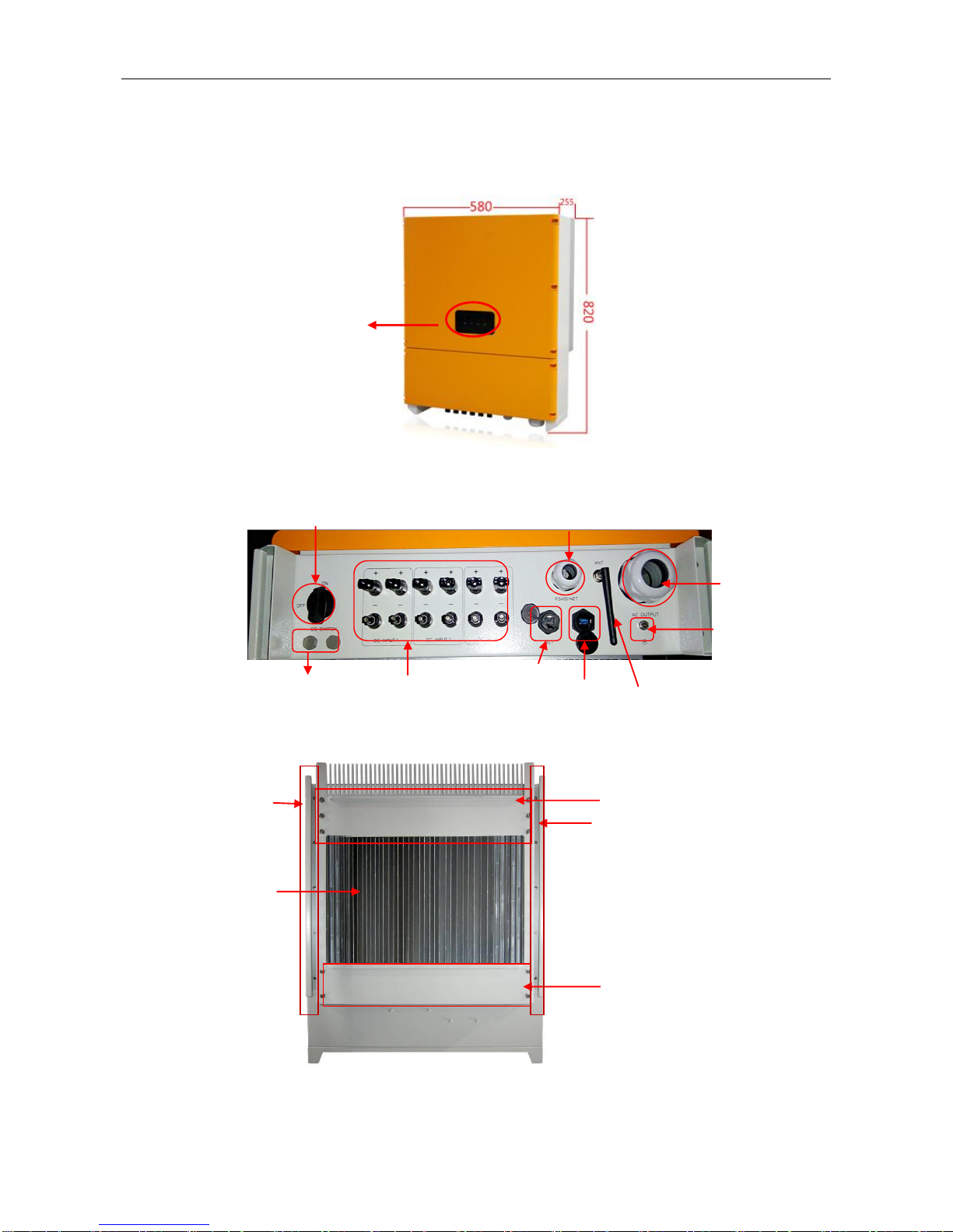
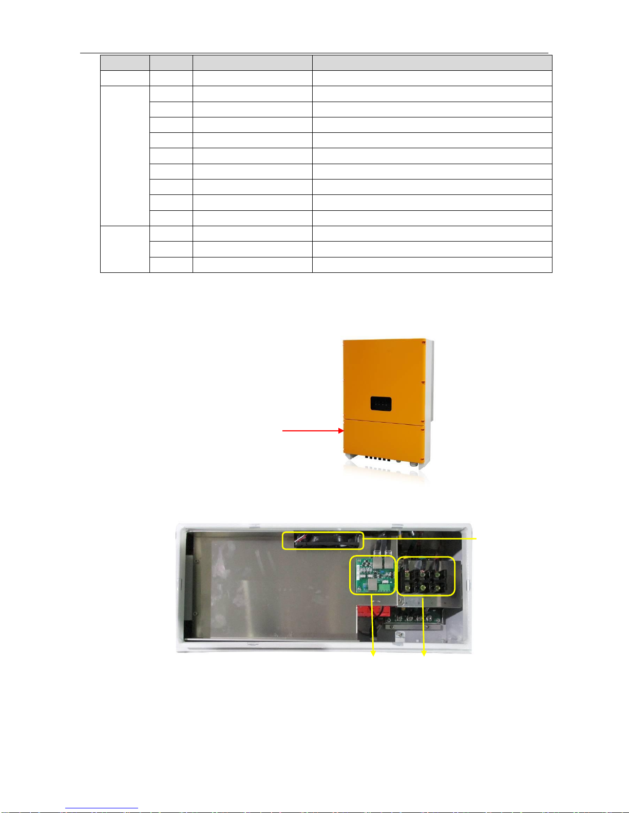
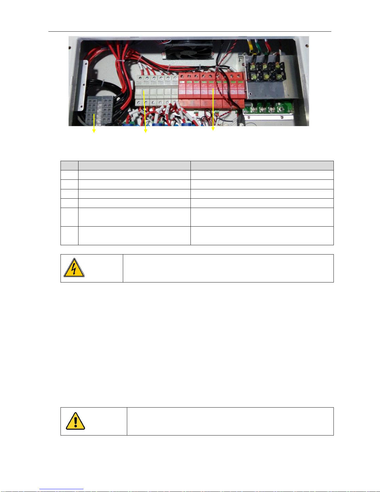
2.4 Product view .........................................................................................................................................................5
3 Installation........................................................................................................................................................................7
3.1 Inspection before installation.................................................................................................................................7
3.2 Transport............................................................................................................................................................... 7
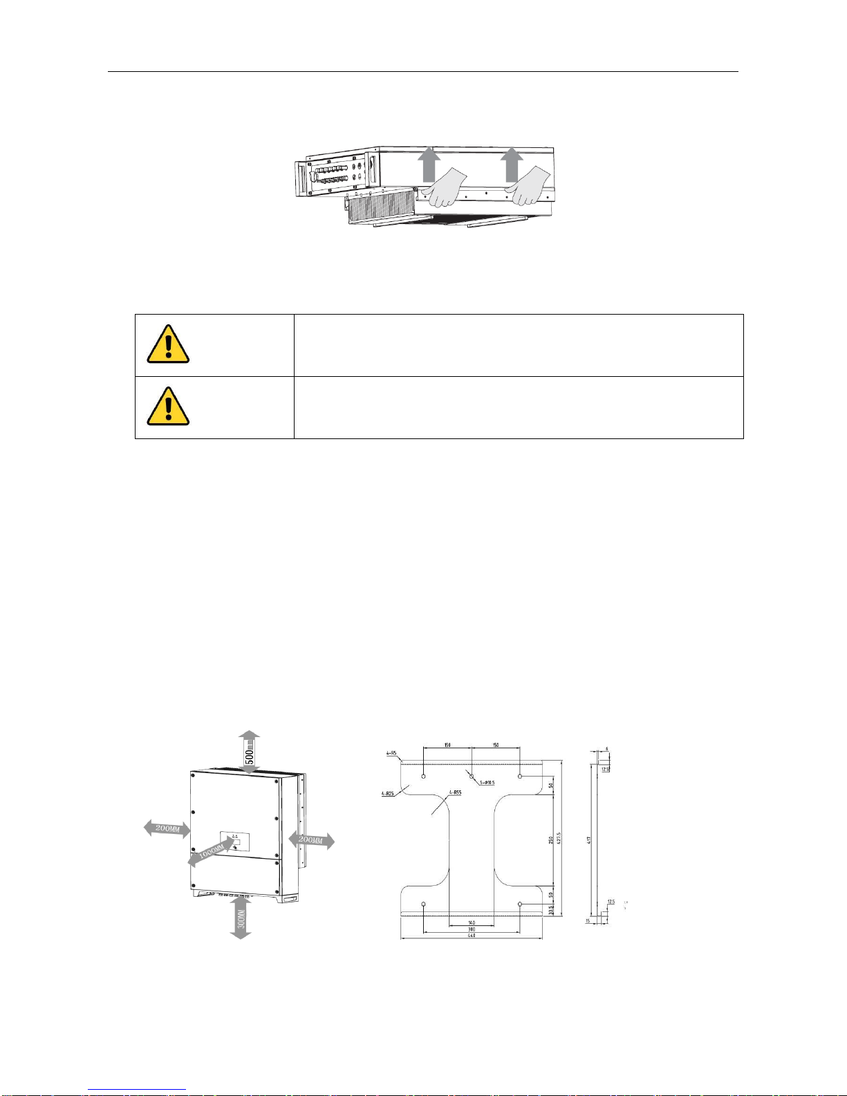
3.3 Mounting...............................................................................................................................................................8
4 Electrical Connection........................................................................................................................................................9
4.1 Cable sizes ...........................................................................................................................................................9
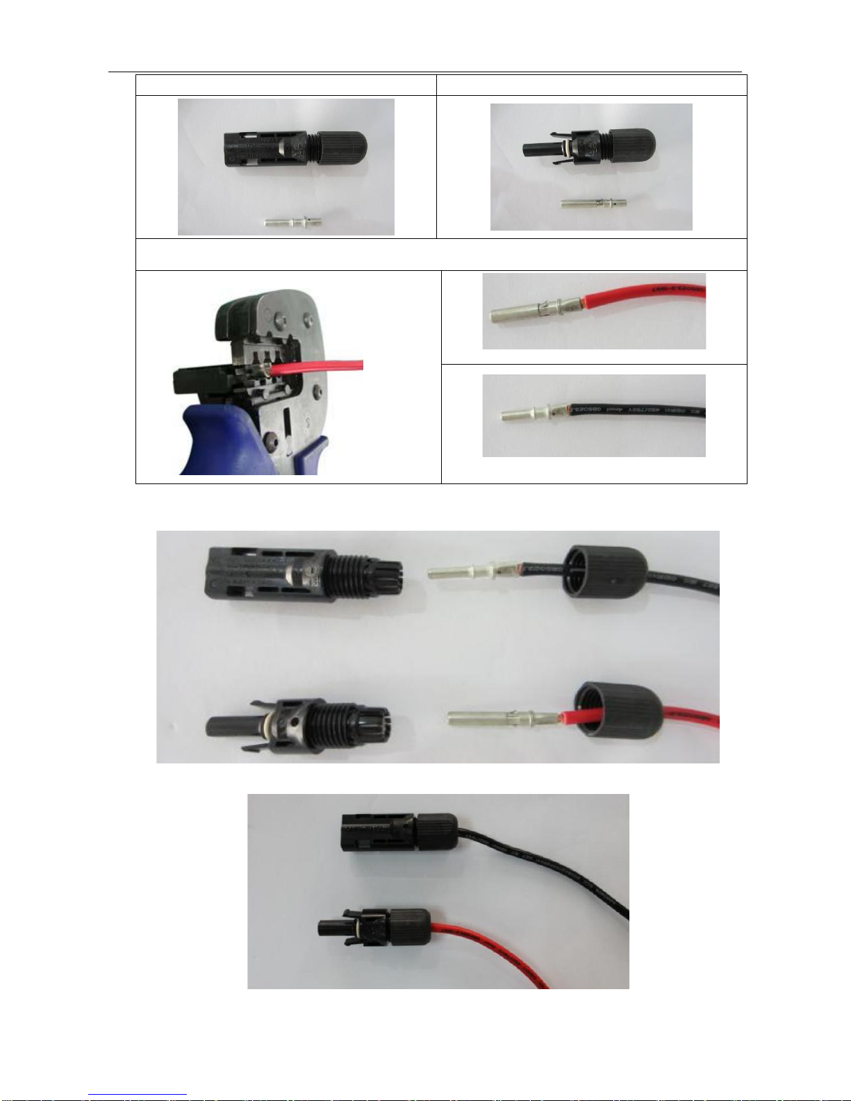
4.2 Making PV input cable and assembling connector................................................................................................ 9
4.3 Making the inverter output cable and installation instructions..............................................................................11
4.4 Making RS485 communication cable and connecting......................................................................................... 12
5 LED Indicator Lights.......................................................................................................................................................12
5.1 LED status information........................................................................................................................................ 12
5.2 View alarm information ....................................................................................................................................... 13
6 Operation .......................................................................................................................................................................14
6.1 Switching On and Off.......................................................................................................................................... 14
6.2 Operation modes ................................................................................................................................................ 15
6.3 Monitoring mode................................................................................................................................................. 16
7 Solar AssistantAPP Operation Manual ..........................................................................................................................17
7.1 Local monitoring APP (iOS &Android) installation.............................................................................................. 17
7.2 Operation of Solar Assistant APP(IOS).......................................................................................................... 18
7.3 Operation of Solar Assistant APP(ANDROID)................................................................................................ 20
7.4 How to distinguish Wi-Fi hotspot......................................................................................................................... 23
8 Troubleshooting..............................................................................................................................................................24
Appendix A........................................................................................................................................................................27

2
1 Important Safety Instructions
Read the manual carefully to become familiar with the equipment before attempting to install, operate, service or
maintain the inverter. Store the manual and other data attached to the product at an easily accessible location.
As standards, specifications and designs are changed from time to time, users should comply with the actual product
purchased if there is any discrepancy between the actual product and the content of the manual.
The product is designed and tested in accordance with international safety requirements, but as with all electrical and
electronic equipment, certain precautions must be observed when installing and operating the product. To reduce the
risk of personal injury and ensure the safe installation and operation of the product, you should carefully read and follow
all instructions, cautions and warnings in this manual.
The following safety message may appear throughout this manual or on the product to warn of potential hazards to call
attention.
Symbol
Description
WARNING
WARNING indicates a hazardous situation which, if not avoided, could result in
serious damage or personal injury.
DANGER
DANGER! HAZARD OF ELECTRIC SHOCK
DANGER indicates a hazard of electric shock, if not avoided, could result in
death or serious injury.
TIPS
TIPS indicate the important information for users to optimize PV system.
Description
Description indicates additional information in the manual, which emphasizes
or supplements on the contents, provides with tips or tricks of the product to
help you solve some problems or save your time.
Safety precautions
WARNING
WARNING! HAZARD OF ELECTRIC SHOCK
EA33/40KTLSI Grid-connected PV inverter must be installed, operated,
serviced and maintained only by trained electrically qualified persons.
Never touch live components in PV system during operating of the inverter.
Follow all safety instructions in this manual.
WARNING
WARNING! Damage to inverter
Input DC voltage must be less than 1000 V, as excessive high voltage may
result in equipment damage.
Inverter should be correctly transported, stored, assembled, installed, operated and maintained.
All operations and wiring should be performed by professional electrical or mechanical engineers so as to ensure
that all electrical installation is in accordance with relevant standard. And in order to ensure safe operation, it is
required to provide correct earthing and necessary short-circuit protection.
Ensure no electricity at DC andAC side before inspection or maintenance.
PV arrays should be covered with lightproof material when they are installed in daytime, otherwise PV arrays will
cause high voltage under sunlight.
After finishing installation or maintenance, firstly close up the AC circuit breaker, and then switch DC power. When
switching DC power, please close up the inverter DC input switch first.
i

3
Follow all instructions in the manual, and completely comply with all danger, warning and safety information.
Storage
If the inverter does not come into use at once, users need to store the inverter and note the following instructions:
Do not unpack.
Maintain a storage temperature of -40℃~+70℃and relative humidity of 5% RH ~ 100% RH.
Storage place free from vibration, conductive dust, direct sunlight and moisture.
The maximum stacking is four floors, excessive stacking may cause equipment damage.
Regular checking is required during storage. Replace packaging if find out any damage by rats or vermin.
After long term storage, the inverter can not come into use until checking by qualified personnel.
2 Product Overview
2.1 Product description
EA33/40KTLSI Grid-connected Inverters apply to PV grid-connected power generation system. In the PV system,
they constantly enable solar panels to output maximum power, and deliver the converted energy from solar panel to
power grid. The PV grid-connected power generation system is composed of PV modules, PV grid-connected
inverters, AC combiner boxes, metering devices and power distribution system, as shown in the Figure 1.
Fig. 1 PV grid-connected power generation system
TIPS
Connecting the product to the electrical utility grid should be approved by the local utility
company, and the connection and operation must be made only by qualified personnel.
2.2 Product features
More energy generated
Transformerless design, maximum conversion efficiency up to 98.6%, Europe efficiency up to 98.4%;
Three MPP inputs, acquiring maximum energy generated by shadowed PV cells
Wide MPPT voltage range (320 ~ 900V), longer daily power generation time
PV modules
PV grid-connected
inverter
Metering device
i
AC combiner
box
Grid

4
Intelligent MPPT algorithm, the maximum power point tracking is not affected by abrupt change of illumination
Accurate identification technology for power change guarantees accurate and stable static MPPT;
Wide operating temperature range (–25 °C ~ + 60 °C), continuous power generation at full load in high temperature
High reliability
Long lifetime design of film capacitor, 25 years of designed service life for complete machine
Natural heat dissipation, waterproof, dust resistance, salt fog resistance and corrosion resistance
Active+passive islanding protection, grid-connected relay redundancy disconnection protection
Multilayer, step-by-step overcurrent, overvoltage, overtemperature and short-circuit protections for software and
hardware
6 strings fault monitoring with rapid positioning
Advanced control technology
Double modulation of three level SPWM and SVPWM, natural and smooth switchover
Adaptive control, adapting to harsh weak power grids environment
Harmonic current compensation, THD < 1%
Supporting active and reactive power grid dispatch and SVG function at night
LVRT function
User-friendly and flexible
Status display with LED indicators, concise interface
Built-in DC SPD and fuse, no need of DC combiner box, reducing cost for users
DC shut-off circuit breaker for safe and convenient maintenance operating
IP 65 protection level for outdoor use
Wall mounting design, one-step forming of aluminum shell
Standard RS485 / APP / GPRS / Wi-Fi / Bluetooth communications; Optional PLC viewing the system operation
information
2.3 Working principle
Figure 2 shows the schematic diagram of EA33//40KTLSI inverter. Electric energy generated by PV module passes
through lightning arrester which absorbs surge voltage at DC side, and capacitive energy storage maintains DC
voltage stable. With the application of three-level SPWM and SVPWM dual modulation, three-phase full-bridge
inverter transforms DC power into AC power with the same frequency and phase as power grid, and sine wave AC
power is generated through filter, high-frequency signal conducted interference is restrained by AC filter, then the
electric energy is sent to the power grid.
Fig. 2 Schematic diagram of EA33/40KTLSI inverter

5
2.4 Product view
Front panel
Bottom panel
Rear panel
11 Handle arm
11 Handle arm
13 Hanging backboard
12 Radiator
4 RS485/NET
2 DC switch
3 PV connectors
10 NET port
7 Air vent valve
6 AC connectors
1 LED indicators
8 External Wi-Fi antenna
9 Grounding
5 USB port
13 Hanging backboard

6
NO.
Name
Description
Front
1
LED Indicators
Indicate inverter status
Bottom
2
DC switch
Control PV input
3
PV connectors
Connect with PV battery
4
RS485/NET
RS485/NET Port
5
USB port
USB port
6
AC connectors
Connect with three-phase AC
7
Air vent valve
Waterproof and breathable
8
External Wi-Fi antenna
External antenna of Wi-Fi module
9
Grounding
Insulation equipment enclosure grounding
10
NET port
NET port
Rear
11
Handle arm
Convenient for handling and installation
12
Radiator
Reduce temperature of inverter power device
13
Hanging backboard
Hang inverter on the wall
Inside
Remove the lower cover of the inverter to see components inside
Remove this cover to
see components inside
2 Communication Lightning protection board
3AC terminals
1 Fan

7
No.
Name
Description
1
Fan
Enhance radiating capacity of radiator
2
Communication Lightning protection board
prevent RS485 and Ethernet cable from lightning strike
3
AC terminals
connect three-phase AC power
4
DC rotary switch
Switch On/Off DC input
5
DC fuse holder / fuse
Avoid damage to the components inside caused by
excessive DC current
6
DC lightning arrester
Avoid damage to the components inside caused by
lightning strike
WARNING
To avoid the risk of electric shock, do not disassemble the cover of the inverter
Make sure the power is completely disconnected before wiring.
3 Installation
3.1 Inspection before installation
EA33/40KTLSI grid-connected inverter has been tested carefully before delivery, while it may be damaged in
transportation. Do not power on and notify the carrier and dealer if find damaged or parts missing.
3.2 Transport
Follow these instructions in the manual to handle with EA33/40KTLSI inverter. Avoid risk of injury due to the inverter
falling during transport.
WARNING
Take the weight and dimensions of the inverter into account. Watch out for falling and
collision during transport.
4 DC rotary switch
子
5 DC fuse holder / fuse
6 DC lightning arrester

8
Two operators hold the handle arms at two sides of inverter, as shown in Figure 3, take out the inverter from the
packing box and carry it to the installation location.
Fig 3 Handling method
3.3 Mounting
CAUTION
Danger to life if installed in improper locations
The mounting location or bracket must be suitable for the weight and
dimensions of the inverter.
CAUTION
Carefully aim at the position and gently hang the inverter on the mounting
frame. Falling may result in damage to inverter or danger to life.
EA33/40KTLSI inverter is suited for indoor and outdoor installation and corresponds to degree of protection IP65.
Mount on a solid support surface. It must be suitable for the weight and dimension of the inverter. The mechanical
dimension of EA33/40KTLSI is 580mmx820mmx255mm (WxHxD), weigh about 65kg.
In order to maintain sufficient ventilation and service access, a clearance between the inverter and surrounding
objects should be observed as following (as shown in Figure 4) : ≥ 200mm at the sides; ≥ 500mm at the top; ≥
300mm at the underside; ≥ 1000mm from the front.
According to the EMC and noise level, the inverter is applicable to industrial environment and should be installed
away from living area as far as possible.
Mount vertically or tilted backwards by max. 15°. Never mount it with a forward tilt. The wiring terminal should be
down.
Place the wall mounting bracket (see Figure 5) against a suitable wall with explosion screws, aim the groove of the
hanging backboard of the inverter at the convex edge of the wall mounting bracket, then attach the inverter to the
wall mounting bracket.
Fig. 4 Minimum clearance Fig. 5 Wall mounting bracket

9
4 Electrical Connection
DANGER
Before the electrical connection, make sure that the inverter is undamaged and in a
safe state.
Before connecting DC terminal cables, ensure the inverter DC switch is
disconnected or PV panels are covered with lightproof material.
All cables must be firmly connected, well insulated and meet the specification
requirements.
The open-circuit voltage of configured PV arrays must be less than 900V.
WARNING
Electrical connection should only be made by electrically qualified personnel.
Prohibit electrical installation under the state of electricity, otherwise it may result in
damage to inverter or danger to life.
TIPS
Connecting the inverter to the electrical utility grid should be approved by the local
utility company
4.1 Cable sizes
Cable
Cable size (mm2)
PV array DC+
Provide 6 inputs, cable diameter > 4mm2
PV array DC-
Provide 6 inputs, cable diameter > 4 mm2
Power grid L1 phase
Provide single input, cable diameter > 10 mm2
Power grid L2 phase
Provide single input, cable diameter > 10 mm2
Power grid L3 phase
Provide single input, cable diameter > 10 mm2
Power grid N
Cable diameter > 10 mm2
Ground wire
Cable diameter > 8 mm2
TIPS
The above table of cable size is based on UL, If use other cables, refer to the
standard for reasonable replacement.
For actual installation cable size, refer to the output value of equipment
specifications.
4.2 Making PV input cable and assembling connector
Step 1: Strip the insulation layer from DC cable about 6mm to expose copper wire, insert the copper wire into the metal
tube core of connector and press it firmly with a crimping plier.
i
i

10
-pole input terminal and tube core
+ pole input terminal and tube core
Strip the cable, insert it into tube core and press it firmly with a crimping plier
Step 2: Loosen the terminal cap and lead cable through the cap. Insert tube core into wire slot until the connection is
completed.
Step 3: Tighten the terminal cap.

11
Step 4: Insert terminals with connected wires into corresponding + and –terminal at the bottom of inverter.
.
4.3 Making the inverter output cable and installation instructions
Step 1: Use wire stripper to strip the sheath and insulation layer from AC output cable at a suitable length, and press the
terminal firmly.
Step 2: Put the AC output cables (L1, L2, L3, N, PE) into the waterproof terminals.
TIPS
Making the inverter output cable and installation instructions is only for reference. Please
note that EA30-33KTLSI output wiring is 3W + N + PE; EA35-40KTLSI output wiring is 3W
+ PE.
For specific internal installation wiring, refer to the output specification value of the inverter
grid.
Step 3: Use a Phillips screwdriver to loosen the bolt in each jack, and insert each cable into the corresponding position,
and then tighten each bolt. PE cable is connected to jack.
Step 4: Tighten the sealing cap to the housing.
i

12
4.4 Making RS485 communication cable and connecting
Recommended RS485 communication cable is 0.5mm2 twisted-pair with 10mm stripping length.
Step 1: Use a wire stripper to strip the insulation layer of RS485 cable at a suitable length.
Step 2: Connect the red tube terminal to the RS485 cable, and press it firmly with a crimping plier.
Step 3: Insert the pressed RS485 cable into the corresponding RS485 waterproof terminal and follow below picture to
connect the cable. (RS485-A on the PCB corresponds to red; RS485-B on the PCB corresponds to black)
5 LED Indicator Lights
5.1 LED status information
There are 4 LED indicator lights on the inverter LED panel to display the system state or alarm.

13
Description of LED main interface
When work normally, LED indicator lights indicates:
Illumination
No illumination
Flash
LED 1 (green)
At least one PV input
PV input voltage is less than 200 V
Unused
LED 2 (green)
The inverter is connected to the
grid
The inverter is not connected to the
grid
Unused
LED 3 (green)
Unused
RS485 communication interruption
RS485 communication
normal
LED 4 (red)
When the inverter is in the state
of self-test, standby, sleep and
shutdown
The system is in the grid-connected
state, and no fault alarm
When the system has
fault alarm
When insert U disk, carry out USB-related operations:
LED 1
(green)
LED 2
(green)
LED 3
(green)
LED 4
(red)
Description
☆
☆
☆
☆
Flashes 5 times, U disk is inserted or
pulled out
☆
☆
☆
○
Loading file
○
○
○
○
No U-disk operation
●
○
○
○
Exporting history
○
●
○
○
Cleaning history
○
○
●
○
Loading firmware upgrade file
●
●
●
☆
Operation fails
●
●
●
○
Operation succeed
☆
○
○
○
DSP1 is in the process of upgrade
☆
○
○
☆
DSP1 upgrade fails
●
☆
○
○
DSP2 is in the process of upgrade
●
☆
○
☆
DSP2 upgrade fails
●
●
☆
○
CPLD is in the process of upgrade
●
●
☆
☆
CPLD upgrade fails
● LED indicator is illuminated ○ LED indicator is not illuminated ☆LED indicator flashes
5.2 View alarm information
User can follow the tips of LED indicator lights to view the inverter fault information.
Export history with U disk.
Connect monitoring and control software via RS485/NET communication to view running information of the
equipment.
Connect APP via Wi-Fi / GPRS (optional) communication devices to view running information of the system.

14
6 Operation
6.1 Switching On and Off
WARNING
Verify again that the voltage at both DC andAC side is in line with the inverter
range allowed.
Switching On
After electrical connection, follow the following steps to turn on EA33/40KTLSI inverter:
Ensure correct connection between inverter and power grid.
Ensure PV array polarity is correct.
Ensure AC and DC terminals are securely fixed;
Close AC output switch
Turn DC switch to “ON” position.
When input voltage is more than 320V and power is more than 200W, the inverter will be automatically operated
with grid connection.
Switching Off
The inverter will be automatically turned off when fails to meet grid-connected conditions. For manual shutdown,
users monitor the inverter via Solar assistant APP, click “Power Off”, here the inverter enters standby state. Under
this state, manual startup is required or the inverter is automatically turned on after power failure, otherwise the
inverter will always be in standby state. Manual startup needs to use Solar assistant APP monitoring the inverter and
click “Power On”.
APP Power On/Off

15
6.2 Operation modes
EA33/40KTLSI supports unattended monitoring, automatic operation and judges if grid-connection power generation
is required according to the output power of PV arrays. The system operation process includes five work status:
startup, grid-connected operation, standby, sleep, shutdown and troubleshooting. Figure 6 presents the operation
mode conversion process for EA33/40KTLSI grid-connected inverter (Vpv means the DC output voltage of PV array)
Startup
Detect fault or shutdown instruction
Vpv> 320V and PV power complies with startup condition
No warning and compliant with operation condition
Insufficient illuminated found
Vpv < 200Vand normal power grid voltage
Fault removed, after 20s
Vpv > 200Vand normal power grid voltage
Detect fault or shutdown instruction
Standby Sleep
Shutdown/Fault
Grid-connection
operation
Fig. 6 Operation mode conversion process
Startup
Startup refers to the preparation stage from standby mode to grid-connected operation mode. In this mode,
grid-connected inverters constantly detect if PV modules have sufficient energy to generate power connected to the
grid, namely when the open-circuit voltage of PV modules is up to 320V and the output power of solar panels is up to
above 200W, PV grid-connected inverters will convert from startup state to grid-connected operation state.
Grid-connected operation
Grid-connected operation mode is that grid-connected inverters convert DC power of PV arrays into AC power and
connect to the power grid. In order to maximize the use of PV arrays energy, the system is designed with maximum
power point tracking (MPPT) control, namely no matter what condition of sunshine and temperature, the system
constantly enable PV arrays to maximize power output.
Standby
Standby refers to the state in which the input voltage of the inverter is more than 200V and less than 320V,
meanwhile parameters of grid voltage and frequency are within allowable range and the inverter has no fault. In this
mode, the inverter constantly detects open-circuit voltage of PV arrays, and accesses to startup state when detects
that its open-circuit voltage is more than 320V.
Sleep
Sleep refers to the state in which the output voltage of PV arrays is less than 200V, fails to support auxiliary power
supply and power grid is normal. When the system detects the output voltage of PV arrays is less than 200V and no
demand for SVG scheduling in night, it will automatically access to sleep state to reduce system energy
consumption.
Normal shutdown or fault
Normal shutdown or fault refers to the specific state in which the system will protect itself when the output power of
PV arrays is low or has shutdown failure.

16
When the output power of PV arrays is low and less than 100W in consecutive 5 minutes, and no demand for SVG
scheduling in night, the system will access to shutdown mode.
When the system detects a failure, it will separate the inverter from the power grid under any circumstances. In this
state, LED fault indicator flashes giving alarm prompt. According to the LED fault alarm prompt, users can view fault
record via communication devices and handle it against the troubleshooting table. When the failure is automatically
cleared, the system will automatically detect whether meet conditions of grid-connected power generation or not in
20s, when conditions are complied, start generating power normally, otherwise maintain the fault state until the
system returns to normal.
Danger
In order to avoid the risk of electrical shock, ensure that the equipment is completely
powered off, and troubleshooting should be made only by qualified personnel.
6.3 Monitoring mode
Wi-Fi communication system
If you purchase optional wireless communication kits, the grid-connected PV inverter is equipped with Wi-Fi wireless
communication function without external RS485 cable. It is used with upper-supervision software or mobile APP to do
real-time monitoring of inverter datas.
Wireless monitoring is divided into two modes, mobile monitoring and computer monitoring. Users need to install PV
inverter monitoring software on computer or install mobile application program.
Wi-Fi module connection has AP mode and STA mode. AP mode is a wireless access point, by which mobile phone,
computer or other devices can be connected to Wi-Fi module. STA mode is a terminal. Wi-Fi module is connected to the
router, and users may connect to the router via mobile phone or computer, and view the real-time inverter datas via
monitoring software on the phone or computer. There are two ways to diagrammatize connection modes as shown below.
Mobile terminal monitoring
Access method 1:
Fig. 7 Mobile phone –Router - Inverter
This access method is most common used. Users can either surf the internet by phone or monitor the inverter datas at
any time.
Access method 2:
Fig. 8 Mobile Phone - Inverter
This access method is used without wireless Router. Users’ phone is directly connected to the inverter via Wi-Fi to
view the inverter datas.

17
Computer terminal monitoring
Access method 1:
User may connect to wireless router via computer, and access Router via Wi-Fi or network cable, and use PV inverter
monitoring software to view the inverter datas.
Fig. 9 Computer- Router- Inverter
Access method 2:
Users’ computer is directly connected to the PV inverter. The computer must be equipped with wireless Wi-Fi function.
Real-time monitoring of the inverter datas can be made with PV monitoring software.
Fig. 10 Computer- Inverter
Wi-Fi module configuration
The inverter Wi-Fi module has two operation modes, AP mode and STAmode. Users may switch working mode by
software in mobile phone or computer. Users should download and install software smartlink3.6.3 in mobile phone and
configure the mode according to specific process. For the computer terminal, users may configure Wi-Fi module
parameter via debugging software SecureCRT, and the default configuration of inverter is AP mode before delivery.
7 Solar Assistant APP Operation Manual
7.1 Local monitoring APP (ISO & Android) installation
7.1.1 Installation information
iOS version installation requires iOS 7.1 and higher system. Android version installation requires Android 4.0 and
higher system. Bluetooth parts require system above 4.3.

18
7.1.2 Solar Assistant APP(IOS)installation
Use mobile browser to input http://www.idbksolar.com/sa/app.html to enter the download page to install App.
Scan below QRCode to enter the installation page (support iOS and Android downloading)
iPhone users can search “Solar Assistant” in App Store to install App.
7.2 Operation of Solar Assistant APP(IOS)
Startup
Find Solar Assistant icon ( ) in desktop and click it.
Fig. 11 Welcome window Fig. 12 Home

19
Devices connection
Step 1: Selecting connection type
Select connection type according to the current configuration of the target device. If the target device is equipped
with blue tooth module, click “BLE Connect”. If the target device is equipped with Wi-Fi module, click “Wi-Fi
Connect”. After clicking the APP, the current hardware and software environment of mobile phone will be judged
automatically for determining whether to support this function or not, if not, theAPP will give tips.
Step 2: Connection
If the Wi-Fi Connect is selected in the first step, it will skip to the interface of Fig. 13, and then click Connect.
Fig. 13 Wi-Fi parameters Fig. 14 Open Bluetooth Fig. 15 Devices Info
If the Bluetooth connection type is selected in the first step, however, Bluetooth is not open from the mobile
phone, the Bluetooth permission will be requested. Here, click [Yes], it will start searching. The available
Bluetooth device will be displayed in the list in the searching process, and click target Bluetooth to connect it.
Step 3:Selecting devices type
Select the first option “ EA10-20/30-40KTLSI”. As shown in Fig. 15.
Step 4:Checking whether the connection is successful or not
It will enter main interface after the third step. If all runs normally, the homepage displays normal datas, as
shown in Fig. 16 and Fig 17. If connection fails, the homepage displays “Loading fails”, as shown in Fig. 18.
Fig. 16 Load successfully Fig. 17 Run normally Fig. 18 Loading fails

20
Devices monitoring
Device data and remote control equipment can be viewed via App after connecting successfully.
Fig. 19 Summary Fig. 20 Present data Fig. 21 Devices Set
Fig. 22 Time Set Fig. 23 RS485 Setting Fig. 24 Net Set
Notice:“Net Set” in the above figure indicates the wired network card address for setting string inverters, which is
irrelevant to Wi-Fi address.
7.3 Operation of Solar Assistant APP(ANDROID)
Startup
Find SolarAssistant icon ( ) in desktop and click it.
Fig. 25 Welcome window Fig. 26 Home
This manual suits for next models
1
Table of contents
Popular Inverter manuals by other brands

FoxESS
FoxESS S Series user manual

Ego Power+
Ego Power+ Nexus Escape Operator's manual

TECO-Westinghouse Motor
TECO-Westinghouse Motor Teco MA7200 Plus Quick start manual

SOLAR VISION
SOLAR VISION ZX60 installation manua

Victron energy
Victron energy Quattro 48/5000/70-100/100 120V manual

Sungrow
Sungrow SG10KTL user manual

SMA
SMA SB 3000TL-US-22 installation manual

Generac Power Systems
Generac Power Systems Quitesource QT036 Specifications

Eaton
Eaton 12-110-1250y Operation and installation guide

Hoymiles
Hoymiles MI-300 user manual

Omnik
Omnik Omniksol-1k-TL-M user manual

CR Remeha
CR Remeha 400 solar Installation & servicing instructions